Tectonic PL-11 Manual

PL-Series Set-up and
Mounng / Rigging Guide
Rev 2.2


Contents
PL-11 Features 4
PL-11 Specs 5
PL-12 Features 6
PL-12 Specs 7
Designing & Aiming Rigging / Mounting Solutions 8
Rigging / Mounting Points 10
Portable Flying 11
Installed Flying 14
VESA Mounting 16
Warranty 18
IMPORTANT SAFETY INFORMATION!
1. Read these instructions.
2. Keep these instructions.
3. Heed all warnings.
4. Follow all instructions.
5. Do not use this apparatus near water.
6. Clean only with a dry cloth.
7. Do not block any ventilation openings. Install in accordance
with manufacturer’s instructions.
8. Do not install near any heat sources such as radiators, heat
registers, stoves, or other apparatus that produce heat.
9. Only use attachments / accessories specified by the manufacturer.
10. Refer all servicing to qualified service personnel.
Servicing is required when an apparatus has been damaged in any way,
such as power-cord or plug is damaged, liquid has been spilled, or objects
have fallen into the apparatus, the apparatus has been exposed to rain or
moisture, does not operate normally, or has been dropped.
11. To reduce the risk of fire or electric shock, do not expose this
apparatus to rain or moisture.
12. The loudspeaker is easily capable of generating sound pressure levels
(SPLs) sufficient to cause permanent hearing damage to performers,
production crew and audience members. Caution should be taken
to avoid prolonged exposure to SPLs in excess of 90 dB.
3

Tectonic PL-11NR Resonant Mode Loudspeaker
The Tectonic PL-11NR Flat Panel Loudspeaker is an ideal choice for small-to medium-sized venues where
an equal audio experience for all seats across a very wide listening area is required.
The PL-11NR is a passive speaker system comprised of a single Distributed Mode Loudspeaker (DML)
mid-high panel. PL-11NR system frequency response is 100Hz – 20kHz (+/-6dB) and is used in
conjunction with subwoofers.
The DML mid-high panel utilizes resonant mode acoustic physics to propagate very wide, diuse audio
energy into a given space. The DML has no cross-over network that can introduce phase and time align-
ment issues or possible distortion in the critical vocal or instrument range.
The PL-11 DML mid-high panel has a horizontal and vertical coverage of 1650, is feed-back resistant
and generates near-zero amounts of odd-order harmonic artifacts and distortion. The net eect is supe-
rior intelligibility throughout a venue.
68.9
2.71”
87.30
3.44”
36.41”
925.00
22.33”
567.00 74.35
2.93”
600.00 (HANDLE SPACING)
23.62”
325.50
12.81”
500.00 (HANDLE SPACING)
181.00
7.13”
141.00
5.55”
486.00
19.13”
19.69”
Dimensions in mm and inches.

Tectonic PL-11NR Specifications
• PL-11 Speaker Frequency Response: 100Hz – 20kHz (+/-6dB)
• PL-11 Speaker Frequency Response: 93Hz – 20kHz (+6/-10dB)
• Continuous Power Rating: 200W RMS
• Program Power / Peak Power: 300W/400W (DML)
• Recommended Amplification: 400W @ 8 ohm (DML)
• Sensitivity: 92dB (DML)
• Peak Output: 118dB
• Nominal Impedance: 8 ohm
• Horizontal Coverage: 165°
• Vertical Coverage: 165°
• Recommended Cross-over Frequencies:
• Sub - LP 100Hz - 18dB/Oct Butterworth
• DML - HP 100Hz - 18dB/Oct Butterworth, LP 16kHz - 12dB/Oct Butterworth
• 925mm W x 567mm H x 74mm D
(36.4" W x 22.3" H x 2.9 D")
• Weight: 26.8 Kg (58.8 lbs.)
Speci ications subject to change without noti ication.
Wiring Diagram
1+
1-
2+
2-
+_+_
+_+_
DML
Speakon™ NL4MP
In/Thru
1+
1-
2+
2-
Speakon™ NL4MP
In/Thru
PIN OUTS
1+ DML 8Ω
POWER LIMITS
1-
DML 400W RMS
not used
not used

Tectonic PL-11 Resonant Mode Loudspeaker
The Tectonic PL-11 Flat Panel Loudspeaker is an ideal choice for small to medium sized venues where an
equal audio experience for all seats across a very wide listening area is required.
The PL-11 is a passive speaker system comprised of a single Distributed Mode Loudspeaker (DML)
mid-range panel and a large format ribbon transducer / horn. PL-11 system frequency response is 90Hz
– 20kHz (+-3dB) and is used in conjunction with subwoofers.
The DML mid-range panel utilizes resonant mode acoustic physics to propagate very wide, diuse audio
energy into a given space. The DML’s diuse output has a frequency response of ~ 90Hz to 9kHz with no
cross-over network that can introduce phase and time alignment issues or possible distortion in the
critical vocal or instrument range.
The PL-11 DML mid-range panel has a horizontal and vertical coverage of 165, is feed-back resistant and
generates near-zero amounts of odd-order harmonic artifacts and distortion. The net eect is superior
intelligibility throughout a venue.
Complementing the PL-11’s DML is an integrated large-format ribbon transducer with a nominal
frequency response of ~7kHz – 22kHz. A shallow horn design provides HF distribution of 120 horizontal
by 15 vertical.
68.9
2.71”
87.30
3.44”
36.41”
925.00
22.33”
567.00 74.35
2.93”
4
600.00 (HANDLE SPACING)
23.62”
325.50
12.81”
500.00 (HANDLE SPACING)
181.00
7.13”
141.00
5.55”
486.00
19.13”
19.69”
Dimensions in mm and inches.
For stereo configurations, place ribbons to the outside.

Tectonic PL-11 Specifications
• PL-11 Speaker Frequency Response: 90Hz – 20kHz (+-3dB)
• PL-11 Speaker Frequency Response: 70Hz – 22kHz (+3dB/-10dB)
• Continuous Power Rating: 200W RMS (DML), 60W RMS (Ribbon)
• Program Power / Peak Power: 300W/400W (DML), 120W/240W (Ribbon)
• Recommended Amplification: 400W @ 8 ohm (DML), 240W@ 12 ohm (Ribbon)
• Sensitivity: 92dB (DML), 103dB (ribbon) @ 1W / 1Meter
• Peak Output: 118dB
• Nominal Impedances: 1 x DML, 8 ohm, 1 x Ribbon, 12 ohm
• Horizontal Coverage: 165° (DML), 120° (ribbon)
• Vertical Coverage: 165° (DML), 15° (ribbon)
• Recommended Cross-over Frequencies:
• Sub to DML ~100Hz, 18dB Butterworth
• DML - to HF Ribbon ~ 6KHz, 12dB Butterworth, with 0.125ms delay for the DML
• 925mm W x 567mm H x 74mm D
(36.4" W x 22.3" H x 2.9 D")
• Weight: 27.2 Kg (60 lbs.)
Speci ications subject to change without noti ication.
Wiring Diagram
+_
1+
1-
2+
2-
+_+_
+_+_
DML
HF Ribbon
Speakon™ NL4MP
In/Thru
1+
1-
2+
2-
Speakon™ NL4MP
In/Thru
PIN OUTS
2+ Ribbon 12Ω
1+ DML 8Ω
POWER LIMITS
1-
2-
DML 400W RMS
Ribbon 240W RMS
5

Tectonic PL-12 Resonant Mode Loudspeaker
The Tectonic PL-12 Flat Panel Loudspeaker is an ideal choice for medium to large spaces where very wide
coverage, high output and extended duty - cycles are required.
The PL-12 is a passive speaker system comprised of a pair of Distributed Mode Loudspeakers (DMLs)
mid-range panels and a large format ribbon transducer / horn.
DML mid-range panels utilize resonant mode acoustic physics to propagate very wide, diuse audio
energy into a given space. The DMLs’diuse output has a frequency response of ~ 90Hz to 6kHz with no
cross-over network that can introduce phase and time alignment issues or distortion in the critical vocal or
instrument range.
The PL-12 DML mid-range panels have a horizontal and vertical coverage of 165, are feed-back resistant
and generate near-zero amounts of odd-order harmonic artifacts and distortion. The net eect is superior
intelligibility throughout a venue.
Complementing the PL-12’s DMLs is an integrated large-format ribbon transducer with a nominal frequen-
cy response of ~6kHz – 22kHz. A shallow horn design provides HF distribution of 120 horizontal by 15
vertical.
948.00 (HANDLE SPACING)
37.33”
486.00
19.14”
566.96
22.32”
326.43 (M)
12.85”
1286.00
50.63”
60.83”
1545.00
500.00 (HANDLE SPACING) 74.35
2.93”
68.77
2.71”
91.67
3.61”
271.60
10.69”
Dimensions in mm and inches.
19.69”
6

Tectonic PL-12 Specifications
• PL-12 Speaker Frequency Response: 80Hz – 20kHz (+-3dB)
• PL-12 Speaker Frequency Response: 60Hz – 22kHz (+3dB/-10dB)
• Continuous Power Rating: 350W RMS (DML), 60W RMS (Ribbon)
• Program Power / Peak Power: 700W/800W (DML), 120W/240W (Ribbon)
• Recommended Amplification: 800W @ 4 ohm (DML), 240W@ 12 ohm (Ribbon)
• Sensitivity: 98dB (DML), 103dB (ribbon) @ 1W / 1Meter
• Peak Output: 127dB
• Nominal Impedances: 2 x DML, 4 ohm, 1 x Ribbon, 12 ohm
• Horizontal Coverage: 165° (DML), 120° (Ribbon)
• Vertical Coverage: 165° (DML), 15° (Ribbon)
• Recommended Cross-over Frequencies:
• Sub to DML ~100Hz, 18dB Butterworth
• DMLs - to HF Ribbon ~ 6KHz, 12dB Butterworth, with 0.125ms delay for the DMLs
• 1545mm W x 567mm H x 74mm D
(60.8" W x 22.3”H x 2.9" D)
• Weight: 45 Kg (98 lbs )
Speci ications subject to change without noti ication.
Wiring Diagram
+_+_
+_
1+
1-
2+
2-
+_+_
+_+_
+_+_
DML 1 DML 2
HF Ribbon
Speakon™ NL4MP
In/Thru
1+
1-
2+
2-
Speakon™ NL4MP
In/Thru
PIN OUTS
2+ Ribbon 12 Ω
1+ DMLs 4Ω
POWER LIMITS
1-
2-
DMLs 800W RMS
Ribbon 240W RMS
7

Designing & AimingTectonic Rigging / Mounting Solutions
Each Tectonic speaker panel is comprised of two types of components:
• One or two very diuse and broad Distributed Mode low-mid to low-high frequency at
panel transducers handling ~ 90Hz - 6KHz.
• A large-format ribbon and wave-guide to cover frequencies from ~6KHz on up.
The DML mid-range panel(s) propagate an extremely wide and diuse acoustic eld that is ~165
wide by 165 high. This extremely wide audio energy is non-interactive with room boundaries in
destructive ways and does not need to be considered when designing a PL Series panel placement
or multiple-panel design. DMLs are audio “Floodlights”and do not need to be specically aimed.
The HF ribbon has a more closely dened coverage pattern of 120 horizontal by 15 vertical. This is
the coverage that should be used to design and aim Tectonic PL Series systems.
When specifying and designing a Tectonic PL Series system, consider the following in this order:
SPL
• Desired SPL from front to back-of-house on main seating level.
• Desired SPL at front and rear of balconies.
• Desired SPL at tertiary locations; transepts, over-ow areas etc.
HF Ribbon Coverage:
• How many panels it takes to provide full vertical coverage to areas with the HF Ribbon’s 15
vertical pattern.
• The angles between panels to provide full and even vertical HF Ribbon coverage.
• The key to designing and aiming a Tectonic PL Series system is to
manage the HF ribbons.
• If the number and aiming of the ribbons achieves the desired HF
vertical coverage, the panels are properly placed.
8
(Cont.)

Designing & AimingTectonic Rigging / Mounting Solutions
The key to designing and aiming Tectonic speakers is to manage the coverage of the 15 x 120
HF Ribbon coverage.
Panels can be connected at angles varying from 0 to 15. The maximum angle between
panels in order to maintain HF Ribbon coupling is 7.
Design tools including Google Sketchup provide accurate positioning and aiming capabilities
for designing a Tectonic speaker system. Here’s an example:
9
Tectonic DML
Coverage:
165 x 165each,
with non-
interactive
overlap.
HF Ribbon Coverage:
~ 15 h x 120 w each.

Tectonic PL Series Rigging & Mounting
WARNING!! - MOUNTING TECTONIC PRODUCTS SHOULD ONLY BE PERFORMED BY TRAINED
AND QUALIFIED PERSONNEL FOLLOWING ALL SAFE MOUNTING STANDARDS, AND MUST
USE ONLY ORIGINAL TECTONIC, ATM ™ AND VESA™ RATED COMPONENTS.
Detailed data sheets and mechanical drawings for all
Tectonic rigging elements are available at
www.tectonicaudiolabs.com as pdf downloads.
• Tectonic panels are only attached to mounting and rigging hardware and do not carry
any load themselves.
•Each Tectonic PL-Series panel ships with integral rigging and mounting stand-offs.
These are the only rigging and mounting connections to the Tectonic panels to be used for safe operation.
Stand-offs receive M8 bolts with a 1:25 pitch.
• Only Tectonicrigging hardware is to be attached to these mounting points.
•PL-11 safety strap attachment points are non-load bearing and to be used only for safety purposes.
486.00
326.43 (M)
12.85”
1286.00
50.63”
Rigging mount / Safety-strap
stand-os.
VESA mount
stand-os.
325.50
12.81”
486.00
19.13”
Rigging and VESA
mount stand-os.
Safety-strap
Attachment Point
Safety-strap
Attachment Point
10

Tectonic PL Series Rigging & Mounting
Detailed data sheets and mechanical drawings for all Tectonic rigging elements
are available at www.tectonicaudiolabs.com as pdf downloads.
Attach a pair of CGF center-of-gravity heads to the HS
rigging tops with load-rated shackles.
The TectonicRigging system is a modular exo-skeleton to which Tectonic PL Series
panels are mounted. At no time is any load placed on the panels themselves.
The Tectonicrigging system provides all of the components to mount or rig
Tectonic PL Series panels in permanent or temporary applications.
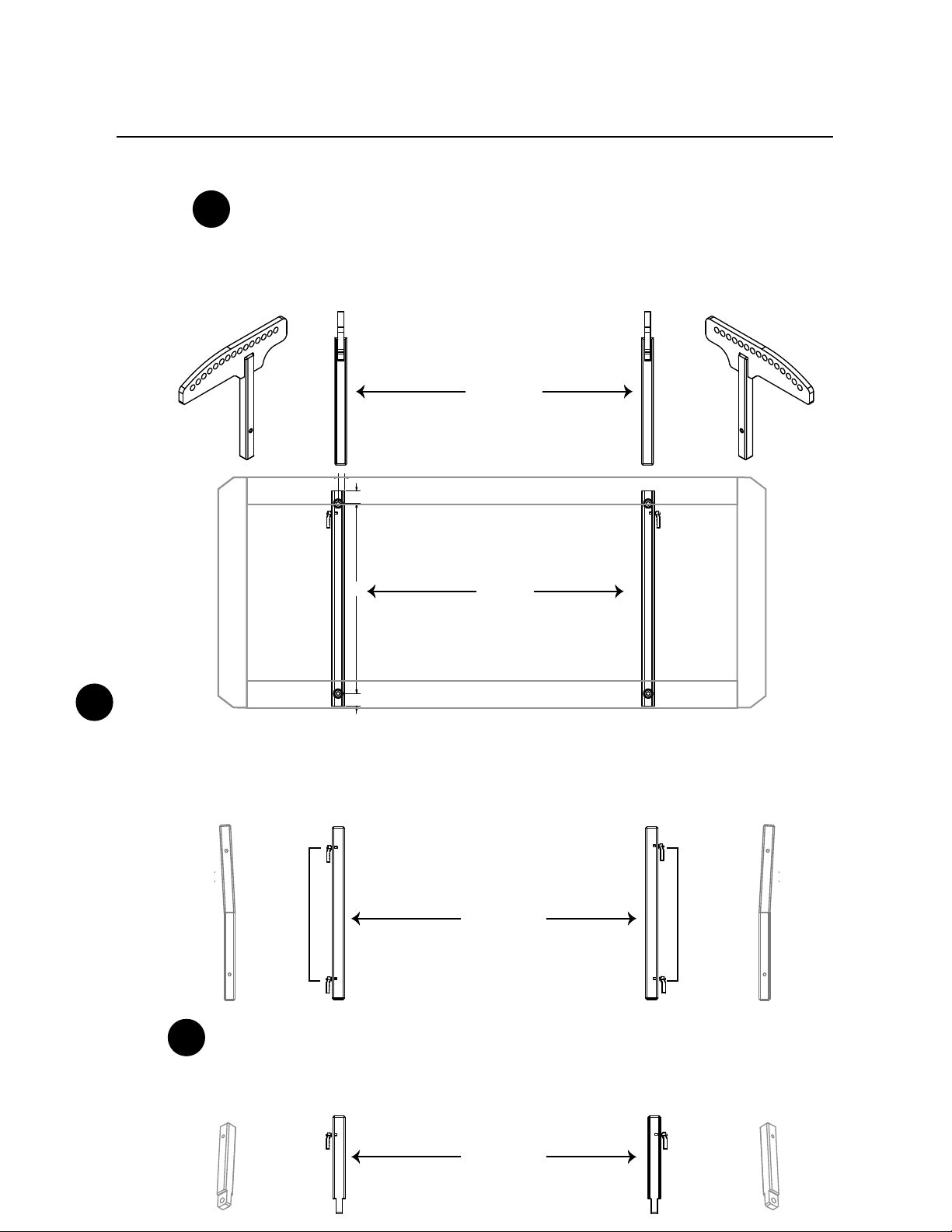
Portable / Temporary Hanging Mount
Attach a pair of CTL rigging mounting tubes to each PL Series panel’s stand-
offs.
Start with an HS-12 or HS-11 rigging top for chain-hoists, spansets etc...
(Cont...)
1
2
3
11
50.63
39.00
24.50
12.81
5.60
3/16
3/16
1/8
1/8
3.00
.50
.265
13.00
9.00
4.251.00
90°
12.84
1.26
1.26 19.13
.63
HS-12
HS-11
Tectonic PL Series Rigging & Mounting
Portable / Temporary Hanging Mount (cont.)
Attach the CGFs to top PL Series panel by inserting
the CGF tail into the panel’s CTL rigging tube and inserting
QPL rigging quick-pins into the mating holes.
CGFs
QPL QPL
QPLs QPLs
CTLs
CBLs
EHLs
QPLs QPLs
Attach additional PL Series panels using your choice of CBL-nn rigging connector
bars in 0, 3, 5, 7 increments. Attach with QPL rigging quick-pins into the mating
holes. CBL connector bars in 10 or 15 can address wide aisle or balcony fasciae
coverage issues
Attach EHL pull-back eye hooks on the last panel, if necessary.
Attach with QPL rigging quick-pins into the mating holes.
4
5
6
12
Mating Holes
Mating Holes
Mating Holes
Mating Holes
Mating Holes
Mating Holes Mating Holes
Mating Holes
1.26
1.26 19.13
.63
(Cont...)

Tectonic PL Series Rigging & Mounting
Portable / Temporary Hanging Mount (cont.)
A fully assembled PL Series portable rig looks like this...
3
13

Tectonic PL Series Rigging & Mounting
Detailed data sheets and mechanical drawings for all Tectonic rigging elements
are available at www.tectonicaudiolabs.com as pdf downloads.
The TectonicRigging system is a modular exo-skeleton to which Tectonic PL Series
panels are mounted. At no time is any load placed on the panels themselves.
The Tectonicflying system provides all of the components to mount or rig Tectonic
PL Series panels in permanent or temporary applications.
Installed Flying Rig
Attach a pair of CTL rigging mounting tubes to each PL Series panel’s stand-offs.
Add a pair of EHL eye hooks to the top of the rst set of rigging tubes with
load-rated 5/16th”x 1.25” bolts.
Attached load rated aircraft cable or chain to the EHLs using load-rated shackles.
(Cont...)
Attach additional PL Series panels using your choice of CBL-nn rigging connector
bars in 0, 3, 5, 7, 10, 15 increments. Attach with load-rated bolts.
1
2
3
14
CBLs
bolts bolts
1.26
1.26 19.13
.63

4
5
Tectonic PL Series Rigging & Mounting
Installed Flying Rig (cont.)
15
Add a pair of EHL eye hooks to the bottom of the
last set of rigging tubes with load-rated bolts.
Attached rated aircraft cable or chain to the EHLs using load-rated shackles.
Use individual pull-backs for each eye hook.
Do not attach a bridle to the eye hooks to use a single pull back!

Tectonic PL Series VESA™ Mounting
Tectonic PL-11 and PL-12 speaker mounting solutions are designed to the VESA
400mm x 400mm standard, and are therefore compatible with any load-rated commercially
available hardware.
the mount. Tectonic is not liable for any mechanical, seismic or other failures beyond the
connection points between said VESA mount and a Tectonic panel.
Only one Tectonic PL Series loudspeaker should be connected to a VESA mount, unless said
system is rated for load and shear limits of adding additional speakers.
Remember that PL panels are not connected to each other. They are connected to the
TectonicVESA mount and the panels themselves carry no load.
outward from the centerline on the speaker.
VML adaptors provide mounting spacing for the 400mm x 400mm VESA standard pattern.
attachment to the VESA mount. Read, understand and follow all instructions that are
provided by the supplier of the VESA mount hardware.
VML VESA Adaptors
WARNING!! - MOUNTING TECTONIC PRODUCTS SHOULD ONLY BE PERFORMED BY TRAINED
AND QUALIFIED PERSONNEL FOLLOWING ALL SAFE MOUNTING STANDARDS, AND MUST USE
ONLY ORIGINAL TECTONICAND VESA™ RATED COMPONENTS.
Detailed data sheets and mechanical drawings for all Tectonic rigging elements
are available at www.tectonicaudiolabs.com as pdf downloads.
16

Tectonic PL Series Rigging & Mounting
Installed VESA Mount
Attach a pair of VML rigging mounting tubes to each PL Series
Panel.
Attach to 400mm VESA mount adaptor or mount using load-rated bolts.
Examples:
Swing Arm Floor Stand
1
2
17
1.00 2.50 1.00
2.000
1.26
2.08
1.26 19.13
.83

Tectonic PL Series Warranty
General:
Five-year limited component warranty on speaker assemblies and
accessories.
WARRANTY CONDITIONS.
a. LIMITED WARRANTY. Each Authorized Product is sold subject to Tectonic’s limited warranty for such Authorized
Product then in eect at the time of shipment. Tectonic shall supply any limited warranty with the Authorized Product
at the time of shipment. Tectonic may make such warranties available via its website. The limited warranty provided is
Tectonic’s sole warranty to Dealer or any third party with respect to the Authorized Products.
b. WHAT IS NOT COVERED BY THE LIMITED WARRANTY: This warranty does not apply to any other hardware or
software products or other items other than the Authorized Products, even if packaged or sold with Authorized
Products. Manufacturers, suppliers, or publishers, other than Tectonic, may provide their own warranties to you but
Tectonic, in so far as permitted by law, provides any third party products "AS IS". This warranty does not apply: (a) to
consumable parts, such as batteries, unless failure has occurred due to a defect in materials or workmanship; (b) to
cosmetic damage, including but not limited to scratches and dents; (c) to damage caused by use of the Authorized
Product with any other product; (d) to damage caused by accident, abuse, misuse, liquid contact, re, earthquake or
other external cause; (e) to damage caused by operating the Authorized Products outside Tectonic’s published
specications; (f) to damage caused by conguration or service to the Authorized Products including upgrades and
expansions performed by Dealer or any third party; (g) to an Authorized Product that has been modied to alter
functionality or capability without the written permission of Tectonic; (h) to defects caused by normal wear and tear
or otherwise due to the normal aging of the Authorized Product; or (i) if any serial number has been removed or
defaced from the Authorized Product.
c. EXCEPT AS SET FORTH IN TECTONIC’S LIMITED WARRANTY, TECTONIC EXPRESSLY DISCLAIMS ALL EXPRESS OR
IMPLIED CONDITIONS, REPRESENTATIONS, AND WARRANTIES INCLUDING, WITHOUT LIMITATION, ANY IMPLIED
WARRANTY OR CONDITION OF MERCHANTABILITY, FITNESS FOR A PARTICULAR PURPOSE, NON-INFRINGEMENT,
SATISFACTORY QUALITY, NON-INTERFERENCE, ACCURACY OF INFORMATIONAL CONTENT, OR ARISING FROM A
COURSE OF DEALING, LAW, USAGE, OR TRADE PRACTICE, ARE HEREBY EXCLUDED TO THE EXTENT ALLOWED BY
APPLICABLE LAW AND ARE EXPRESSLY DISCLAIMED BY TECTONIC. TO THE EXTENT AN IMPLIED WARRANTY CANNOT
BE EXCLUDED, SUCH WARRANTY IS LIMITED IN DURATION TO THE EXPRESS WARRANTY PERIOD. BECAUSE SOME
STATES OR JURISDICTIONS DO NOT ALLOW LIMITATIONS ON HOW LONG AN IMPLIED WARRANTY LASTS, THE ABOVE
LIMITATION MAY NOT APPLY. THIS WARRANTY GIVES CUSTOMER SPECIFIC LEGAL RIGHTS, AND CUSTOMER MAY ALSO
HAVE OTHER RIGHTS WHICH VARY FROM JURISDICTION TO JURISDICTION. This disclaimer and exclusion shall apply
even if the express warranty set forth above fails of its essential purpose.
d. DEALER’S OBLIGATIONS. DEALER SHALL NOT BY STATEMENT OR IMPLICATION, ALTER, ADD TO, AUGMENT OR
MISREPRESENT TECTONIC’S LIMITED WARRANTY. DEALER SHALL KEEP RECORDS OF ITS SALE OF ALL AUTHORIZED
PRODUCTS WHICH WILL INCLUDE THE NAME AND ADDRESS OF ANY CUSTOMER, THE DATE OF THE SALE, THE MODEL
AND SERIAL NUMBERS OF THE AUTHORIZED PRODUCT AND ANY OTHER RELEVANT INFORMATION. DEALER’S SOLE
REMEDY FOR ANY BREACH OF TECTONIC’S LIMITED WARRANTY SHALL BE REPAIR OR REPLACEMENT OF DEFECTIVE
AUTHORIZED PRODUCTS OR, IN TECTONIC’S SOLE OPTION, THE REFUND OF THE PURCHASE PRICE.
18
Other manuals for PL-11
1
This manual suits for next models
2
Table of contents


