TeeJet Technologies RXA-52 User manual

USER GUIDE
98-01569-EN-R1_A4LT-RXA52-UG.docx
1
RXA-52
MULTI-FREQUENCY, MULTI-CONSTELLATION, GNSS ANTENNA
Thank you for choosing TeeJet Technologies’ RXA-52 as your
GNSS antenna solution. This document provides instructions for
mounting and operation of the RXA-52. Contact a local dealer for
more information or visit www.teejet.com.
The RXA-52 is an active antenna designed to receive signals
from GPS, GLONASS, BeiDou and Galileo satellites as well as L-
Band signals.
The RXA-52 antenna is designed to operate in GPS L1/L2,
GLONASS L1/L2 and L-Band frequencies. The RXA-52 also
supports the Galileo E1 and E5b frequencies as well as BeiDou
B1 and B2 frequencies.
It can be used with any console with an internal GNSS receiver or
any device with an antenna input port that both receives the RF
signal and provides 3.3 - 18.0 VDC to the antenna
RXA-52 Kit Includes
•RXA-52 Antenna
•Coaxial Cable, SMA male to TNC male, 20′/6 m (part number 45-05957) or 30′/9 m (part number 45-05620)
•Mounting Plate (part number 65-05243)
INSTALLATION
Site Selection Guidelines
Before installing the antenna, select a site that as closely as possible meets the following conditions for optimal performance:
•An unobstructed line-of-sight from horizon to horizon and at all bearings and elevation angles
•As far as possible from reflective objects, especially those that are above the antenna and any water bodies, which can be a strong
source of multipathreflections
•If obstructions and reflective surfaces are within 100 feet / 30 meters, ensure the site is as high as possible. Otherwise, mount the
antenna as close as possible to a reference ground plane, i.e., rooftop, earth, etc., if one exists.
•When mounting the RXA-52 Antenna, a space of at least 5.9 inch / 15 cm between the antenna and any bend in the cable is
required. Any length shorter than 5.9 inch / 15 cm puts undue stress on the cable and the enclosure for the RXA-52.
•The antenna should not be mounted where water can pool around it. The antenna housing is designed to withstand rain and
splashing, but not submersion in liquids for sustained periods of time.
•Mount the antenna above all other metal objects to avoid multipath. Satellite signals received by the GNSS antenna by a reflection
from an object can decrease positioning accuracy. For example, roof racks, large headlight enclosures, etc., can cause multipath
that may result in a jump in GNSS position.
Warning! To avoid potential adverse effects, do not locate antennas near any high sources of heat.
USER GUIDE TEEJET TECHNOLOGIES
98-01569-EN-R1_A4LT-RXA52-UG.docx
2
Installing the Antenna
After a site has been selected, install the antenna as follows:
1. Mount the antenna on a secure, stable structure using the provided magnetic mounts. A surface mounting plate (Part Number
65-05243) is also available for mounting on non-magnetic surfaces. See Mounting Plate Instructions for details.
2. Attach the TNC connector of the coaxial cable to the antenna’s TNC connector. Attach the other end of the coaxial cable to the
antenna input port of the receiving device, which must provide power as detailed in the “Specifications” section of this guide. All
TeeJet Technologies GNSS receivers provide the necessary power through their antenna RFconnectors.
Figure 1: Orientation Example
Orient antenna towards the front of the vehicle.
Route cable toward the back of vehicle.
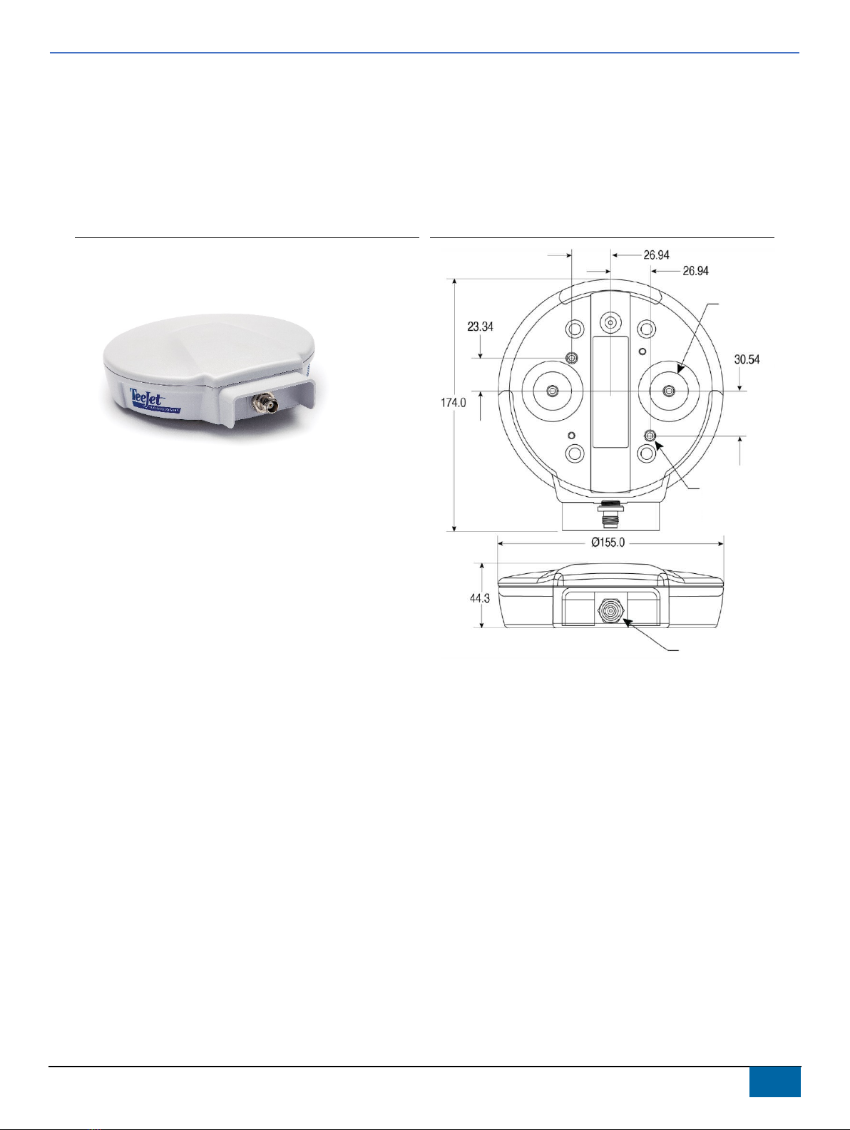
Figure 2: RXA-52 Dimensions in Millimeters
Front
Back
Mounting
Magnet
× 2
M
4 × 0.7 Threaded
Insert
× 2
TNC Connector

USER GUIDE TEEJET TECHNOLOGIES
98-01569-EN-R1_A4LT-RXA52-UG.docx
3
Mounting Plate Instructions
The RXA-52 is equipped with two (2) built-in magnets for attaching to the included mounting bracket. If a permanent mount for the
RXA-52 is required, please contact TeeJet Technologies Technical Support for more information.
Intermediate Mounting Plate Template
A template for the intermediate mounting plate has been provided below.
•Red circles indicate holes where attachment will occur.
•Green lines indicate the outline of the mount and other holes for attaching the release plate.
WARNING! The optimal screw penetration into the mounting holes is 0.25 inch / 6 mm (±1/32 inch / 1 mm) deep. When selecting
screws for mounting, ensure the screw penetration does not exceed this specification. Using excessively long screws can
damage the antenna enclosure.
Antenna Care
•The RXA-52 is designed to withstand the elements, including rain, snow, and dust.
•However, to ensure your antenna performs optimally, keep the radome (the top surface of the antenna) clean and brush off any ice
and snow.
6.25 inch
158.75 mm
5.0 inch
127.0 mm
0.50 in
ch × 4
12.7 mm × 4
0.50 in
ch × 4
12.7 mm × 4
Ø0.27 inch ± 0.01 inch
drill thru × 4
Ø6.858 mm ± 0.01 mm drill thru × 4
This side will route
t
oward back of vehicle

USER GUIDE TEEJET TECHNOLOGIES
98-01569-EN-R1_A4LT-RXA52-UG.docx
4
SPECIFICATIONS
Performance
Signal Received
GPS ...............................................................................L1, L2
GLONASS ......................................................................L1, L2
Galileo ......................................................................... E1, E5b
BeiDou ..........................................................................B1, B2
L-Band
Pass Band (typical)
Upper passband ....................................... 1588.0 ± 23.0 MHz
Lower passband ....................................... 1220.0 ± 31.0 MHz
L-Band ......................................................1555.0 ± 10.0 MHz
Out-of-Band Rejection
Band edges ± 50 MHz ......................................15 dB (typical)
Band edges ± 100 MHz ....................................25 dB (typical)
LNA Gain (typical)
L1 ................................................................................... 34 dB
L2 ................................................................................... 38 dB
Gain at Zenith (90°)
L1/B1/E1/G1 ............................................. +4.0 dBic minimum
L2/B2/E5b/G2 ........................................... +4.0 dBic minimum
L-Band ...................................................... +4.0 dBic minimum
Gain Roll-Off (from Zenith to Horizon)
L1/B1/E1/G1 .................................................................. 12 dB
L2/B2/E5b/G2 ................................................................ 12 dB
L-Band ........................................................................... 12 dB
Phase Center Stability
....................................................................................<5.0 mm
Polarization
....................................................................Right-hand circular
Noise Figure
..........................................................................2.5 dB (typical)
VSWR
..................................................................................... ≤2.0 : 1
L1-L2 Differential Propagation Delay
........................................................................7 ns (maximum)
Group Delay Ripple
.......................................................................................<15 ns
Nominal Impedance
.......................................................................................... 50 Ω
Physical and Electrical
Dimensions
................................................ 6.1 in W × 1.77 in H × 6.85 in L
...........................................155 mm W × 45 mm H ×174 mm L
Weight
........................................................................ 15.88 oz / 450 g
Mounting
................................................................ 2 × magnetic mounts
.................................................................2 × M4 screw inserts
Power
Input voltage .............................................. +3.3 to +18.0 VDC
Current .............................................................20 mA (typical)
Environmental
Temperature
Operating ...........................-40°F to +185°F / -40°C to +85°C
Storage ..............................-67°F to +185°F / -55°C to +85°C
Humidity
................................................................ 95% non-condensing
Salt Fog
....................................................MIL-STD-810G (CH1), 509.6
Water/Dust Resistance
...............................................................................IP67, IP69K
Vibration (operating)
Random ............MIL-STD-810G (CH1), 514.7 (15 g) Annex E
Procedure 1, Category 24
Shock
.....................MIL-STD-810G (CH1), 516.7 (40 g) Procedure 1
Bump
.........................................................IEC 60068-2-27 Ea (25 g)
Compliance
......................................................................... FCC, CE, ISED
RoHS ...................................................EU Directive 2011/65/EU
Warranty
1 year from date of purchase.
English-International www.teejet.com
© TeeJet Technologies 2021
Other TeeJet Technologies Antenna manuals

Popular Antenna manuals by other brands

Winegard
Winegard TRAV'LER SHAW DIRECT SK-7003 installation manual

A.H. Systems
A.H. Systems SAS-517 Operation manual

KVH Industries
KVH Industries TrackPhone V7 user guide

A.H. Systems
A.H. Systems AK-18G Operation manual

Bodet
Bodet 907 048 installation manual

Ventev
Ventev M6060060P1D43699D quick start guide


