Telguard Digital TG-11 User manual

TELGUARD® DIGITAL
TG-11
Residential and Commercial
Cellular Alarm Communicator
Cellular Alarm Transmission System
Using GSM Digital Cellular Technology
MODEL TG11G001
56039504 08/20/2008 © 2008 Telular Corporation
INSTALLATION AND OPERATING INSTRUCTIONS
Technical Support: 800-229-2326
M-F 8:00AM – 8:00PM EST
Saturday 8:00 AM – 5:00 PM EST
COMPANY CONFIDENTIAL
For use by TELGUARD®customers only.
Distribution to others strictly prohibited under penalty.
Revised August 20, 2008
TELGUARD®is a registered trademark of Telular Corporation. Products are
protected under one or more of the following U.S. patents:
4,658,096 4,737,975 4,775,997 4,868,519 4,922,517
© 2008 Telular Corporation

56039504 08/20/2008 © 2008 Telular Corporation
i
FOREWORD
Many customers purchase Telguard®Digital products for its competitive price and superior features. The
Telguard model TG11G001 (TG-11) is UL Listed for Household Fire systems, Household Burglary systems
and Commercial Burglary Systems Use. This means that the TG11 may be used in Household Burglary,
Household Fire systems or Commercial Burglary as the main or secondary communication line.
ABOUT THIS MANUAL
This manual assumes that you have basic security system installation skills such as measuring voltages,
stripping wire, properly connecting wires together, connecting wires to terminals, and checking phone
lines. It also assumes that you have a familiarity with the proper installation and programming tasks
related to various control communicator panels.
The material and instructions covered in this manual have been carefully checked for accuracy and are
presumed to be reliable. However, Telular assumes no responsibility for inaccuracies and reserves the
right to modify and revise this manual without notice.
It is our goal at Telular to always supply accurate and reliable documentation. If a discrepancy is found in
this documentation, please mail or fax a photocopy of the corrected material to:
Telular Security Products
Technical Services Department
2727 Paces Ferry Rd
Atlanta, GA 30339
Fax: 678-945-1651
© 2008 Telular Corporation. Atlanta, GA U.S.A. All rights reserved.
NOTICES
FCC NOTICES
EXPOSURE TO RADIO FREQUENCY ENERGY
In 1991, the Institute of Electrical and Electronics Engineers (IEEE), and in 1992, the American National
Standards Institute (ANSI), updated the 1982 ANSI Standard for safety levels with respect to human
exposure to RF energy. Over 120 scientists, engineers and physicians from universities, government
health agencies and industry, after reviewing the available body of research, developed this updated
Standard. In March 1993, the U.S. Federal Communications Commission (FCC) proposed the adoption
of this updated Standard.
The design of your Telular Telguard complies with this updated Standard. Of course, if you want to limit
RF exposure even further than the updated ANSI Standard, you may choose to install the unit in a
manner that locates its antenna at an even greater distance from the general public than is recommended
as a minimum by the standard.
To insure compliance with the standard, when selecting a mounting location for your Telguard do not
mount it (or its associated antenna) in an area where the general public could reasonably be within 8
inches (20 centimeters) of the antenna.
EFFICIENT OPERATION
Do not operate your Telular product when holding the antenna. Be sure to mount the unit such that its antenna
is kept at a minimum of eight (8) inches (20 centimeters) away from the general public.
For the best service quality, keep the antenna free from obstructions and point the antenna straight up.
ANTENNA CARE AND OPERATION
Do not use the unit with a damaged antenna. If a damaged antenna comes into contact with the skin, a
minor burn may result. Have your antenna replaced by a qualified technician immediately. Use only a

56039504 08/20/2008 © 2008 Telular Corporation
ii
manufacturer-approved antenna. Non-approved antennas, modifications, or attachments could impair
service quality, damage the Telguard and violate FCC regulations.
ELECTRONIC DEVICES
Most modern electronic equipment is shielded from RF energy. However, RF energy from cellular devices
may affect inadequately shielded electronic equipment. RF energy may affect improperly installed or
inadequately shielded electronic equipment operating in homes and businesses. Check with the
manufacturer or its representative to determine if these systems are adequately shielded from external
RF energy. Consult the manufacturer of any personal medical devices (such as pacemakers, hearing
aids, etc.) to determine if they are adequately shielded from external RF energy.
BLASTING AREAS
To avoid interfering with blasting operations, turn OFF your unit when in a “blasting area” or in areas
posted: “Turn off two-way radio.” Construction crews often use remote control RF devices to set off
explosives.
POTENTIALLY EXPLOSIVE ATMOSPHERES
Turn OFF your unit when in any area with a potentially explosive atmosphere. It is rare, but the Telguard
Digital product or its accessories could generate sparks. Sparks in such areas could cause an explosion
or fire resulting in bodily injury or even death. Areas with a potentially explosive atmosphere are often, but
not always, clearly marked. They include fueling areas such as gas stations; below deck on boats; fuel or
chemical transfer or storage facilities; areas where the air contains chemicals or particles, such as grain,
dust, or metal powders; and any other area where you would normally be advised to turn off your vehicle
engine.
Do not transport or store flammable gas, liquid or explosives in the area of your Telguard Digital product
and accessories.
Vehicles using liquefied petroleum gas (such as propane or butane) must comply with the National Fire
Protection Standard (FPA-58). For a copy of this standard, contact the National Fire Protection
Association, One Batterymarch Park, Quincy, MA 02269, Attn: Publications Sales Division.
FUTURE TESTING AND LIMITATIONS ON USE
The Telguard®Digital device is part of an advanced design alarm-communication system. It does not
offer guaranteed protection against burglary and fire. Any alarm communication system is subject to
compromise or failure.
The Telguard®Digital device will not work without power. Devices powered by AC will not work if the AC
power supply is off for any reason, however briefly, and at the same time, a backup battery is missing,
dead or not properly installed.
The cellular radio network, needed to transmit alarm signals from a protected premise to a central
monitoring station, may be inoperable or temporarily out of service. Cellular radio networks are also
subject to compromise by sophisticated methods of attack.
This equipment, like any other electrical device is subject to component failure. Although this equipment
is designed to be long lasting, the electrical components could fail at any time.
Due to these limitations, we recommend that if the automatic self-test feature is not enabled, other
arrangements be made with the user to test the system at least once every three months. Moreover,
arrangements should also be made for on-site inspection/test by a licensed alarm installer at least once
each year.

56039504 08/20/2008 © 2008 Telular Corporation
iii
TERMS AND CONDITIONS FOR USE OF TELGUARD®PRODUCTS (“Product”)
These Terms and Conditions are a legal contract between you and Telular Corporation for the title to and
use of the Product. BY RETAINING AND USING THE PRODUCT YOU AGREE TO THE TERMS AND
CONDITIONS INCLUDING WARRANTY DISCLAIMERS, LIMITATIONS OF LIABILITY AND
INDEMNIFICATION PROVISIONS BELOW. IF YOU DO NOT AGREE TO THE TERMS AND
CONDITIONS, DO NOT USE THE PRODUCT AND IMMEDIATELY RETURN THE UNUSED PRODUCT
FOR A COMPLETE REFUND. You agree to accept sole responsibility for any misuse of the Product by
you; and, in addition, any negligent or illegal act or omission of your or your agents, contractors, servants,
employees, or other users of the Product so long as the Product was obtained from you, in the use and
operation of the Product.
INDEMNIFICATION OF TELULAR CORPORATION (“TELULAR”)
YOU SHALL INDEMNIFY, DEFEND AND HOLD HARMLESS TELULAR FOR ANY OF THE COST,
INCLUDING REASONABLE ATTORNEYS’ FEES, AND FROM CLAIMS ARISING OUT OF YOU,
YOUR CLIENTS’ OR OTHER THIRD PARTIES’ USE OR OPERATION OF THE PRODUCT: (i) FOR
MISUSE OR IN A MANNER NOT CONTEMPLATED BY YOU AND TELULAR OR INCONSISTENT
WITH THE PROVISIONS OF THIS MANUAL; (ii) IN AN ILLEGAL MANNER OR AGAINST PUBLIC
POLICY; (iii) IN A MANNER SPECIFICALLY UNAUTHORIZED IN THIS MANUAL; (iv) IN A MANNER
HARMFUL OR DANGEROUS TO THIRD PARTIES; (v) FROM CLAIMS BY ANYONE RESPECTING
PROBLEMS, ERRORS OR MISTAKES OF THE PRODUCT; OR (vi) COMBINATION OF THE
PRODUCT WITH MATERIAL, MODIFICATION OF THE PRODUCT OR USE OF THE PRODUCT IN AN
ENVIRONMENT NOT PROVIDED, OR PERMITTED, BY TELULAR IN WRITING. THE PARTIES
SHALL GIVE EACH OTHER PROMPT NOTICE OF ANY SUCH COST OR CLAIMS AND
COOPERATE, EACH WITH THE OTHER, TO EFFECTUATE THIS INDEMNIFICATION, DEFENSE
AND HOLD HARMLESS.
WARRANTY; LIMITATIONS
TELULAR WILL REPAIR OR REPLACE (OUR OPTION) INOPERATIVE UNITS FOR UP TO TWO YEARS
FROM DATE OF MANUFACTURE. EXCLUDES DAMAGE DUE TO LIGHTNING OR INSTALLER
ERROR AS WELL AS UNITS THAT INCORPORATE MATERIAL, OR USED IN A MANNER OR
ENVIRONMENT, NOT SPECIFICALLY AUTHORIZED IN THIS MANUAL. UNAUTHORIZED
MODIFICATIONS VOID THIS WARRANTY. NOT RESPONSIBLE FOR INCIDENTAL OR
CONSEQUENTIAL DAMAGES. LIABILITY IS LIMITED TO PRICE OF UNIT. THIS IS THE EXCLUSIVE
WARRANTY, IN LIEU OF ALL OTHER WARRANTIES INCLUDING IMPLIED WARRANTIES OF
MERCHANTABILITY, TITLE, DELIVERY, INFRINGEMENT OR FITNESS FOR A PARTICULAR
PURPOSE AND NO OTHER WARRANTIES WILL BE HONORED, WHETHER EXPRESSED OR
IMPLIED.

56039504 08/20/2008 © 2008 Telular Corporation
iv
TABLE OF CONTENTS
FOREWORD...............................................................................................................................................I
ABOUT THIS MANUAL ..............................................................................................................................I
NOTICES....................................................................................................................................................I
FUTURE TESTING AND LIMITATIONS ON USE ....................................................................................II
1.0UL LISTINGS ..............................................................................................................................1
2.0PRE-INSTALLATION CHECKLIST.............................................................................................1
3.0INSTALLATION STEPS..............................................................................................................1
4.0POWER MANAGEMENT............................................................................................................6
5.0 REMOTE PANEL DOWNLOADING ...........................................................................................6
6.0LED DESCRIPTIONS.................................................................................................................7
7.0SYSTEM SPECIFICATIONS ......................................................................................................9
A1ACTIVATION FORM.................................................................................................................10
A2WARRANTY..............................................................................................................................11
A3PARTS LIST..............................................................................................................................11
1.0 UL LISTINGS
Model TG11G001 (TG-11) meets the requirements for all Household Burglary, Household Fire, and Combined
Household Burglary/Fire installations. It has a plastic enclosure and dipole antenna. TG11 is UL Listed for the
following:
•UL Household Burglary (NBSX)
•UL Commercial Burglary (APAW: Police Station – Burg and AMCX: Central Station Burg)
•UL Household Fire (UTOU)
2.0 PRE-INSTALLATION CHECKLIST
Before installing and configuring the TG-11, use the following checklist to ensure that you have all the necessary parts
included in the TG-11 box:
Part Quantity
ANT, 0DBD,DIPOLE 800/1900MHZ, TNC-MALE 1
WASHER, FLAT, ID .515, OD 1.220, ALUMINUM 2
WASHER, FLAT, ID.878, OD 1.248, ALUMINUM 1
CONDUIT LOCK NUT, 1/2-14, ZINC 1
BRACKET, TNC SUPPORT 1
SCREW, #6 X 1-1/4 METAL, PNH, COMBO, ZP 3
Table 2. 1
3.0 INSTALLATION STEPS
Installation of the TG11 unit shall ONLY be performed in the following ways as demonstrated.
Any other method of installation is not approved by UL and not recommended.
Installation Tip: It is highly recommended to activate cellular service prior to leaving for the job
site. This will avoid a second trip to the site. To register the unit, simply fill out the attached
form (page 10) and fax it back to (678) 945-1651 or email the completed form to
[email protected]. For faster service, register online, at http://www.TelguardOnline.com
or complete the registration information at www.telguard.com.
STEP 1. Open the front of the Honeywell VISTA cabinet. Disconnect both the backup battery connection and the
wall transformer, ensuring that the control panel is completely powered off. Determine whether the TG-11 can be
mounted internal or external to the cabinet, based on the amount of free space within the cabinet.
If there is NOT enough room inside the cabinet, then you will need to install the TG-11 externally. To do this,
knock out one of the pre-punched holes either on the top of the cabinet (Figure 3. 3 – External Top Mount) or on
the right-side (Figure 3. 2 – External Side Mount). Feed the ECP wires and the antenna cable through the punch-
out, followed by the TG-11 threaded stem. Secure the TG-11 with the supplied nut and HAND TIGHTEN ONLY.
(Use the diagrams below as reference)
56039504 08/20/2008 © 2008 Telular Corporation
1
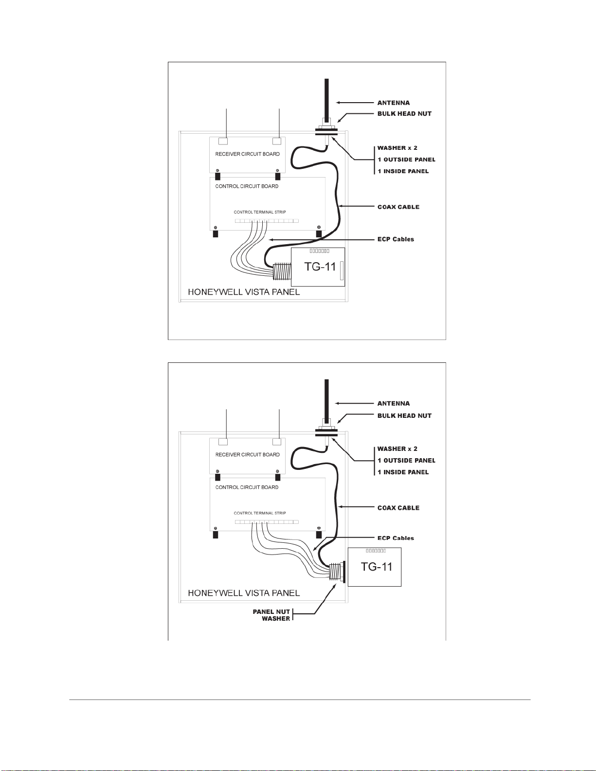
Figure 3. 1 – Internal Mount
Figure 3. 2 – External Side Mount
56039504 08/20/2008 © 2008 Telular Corporation
2
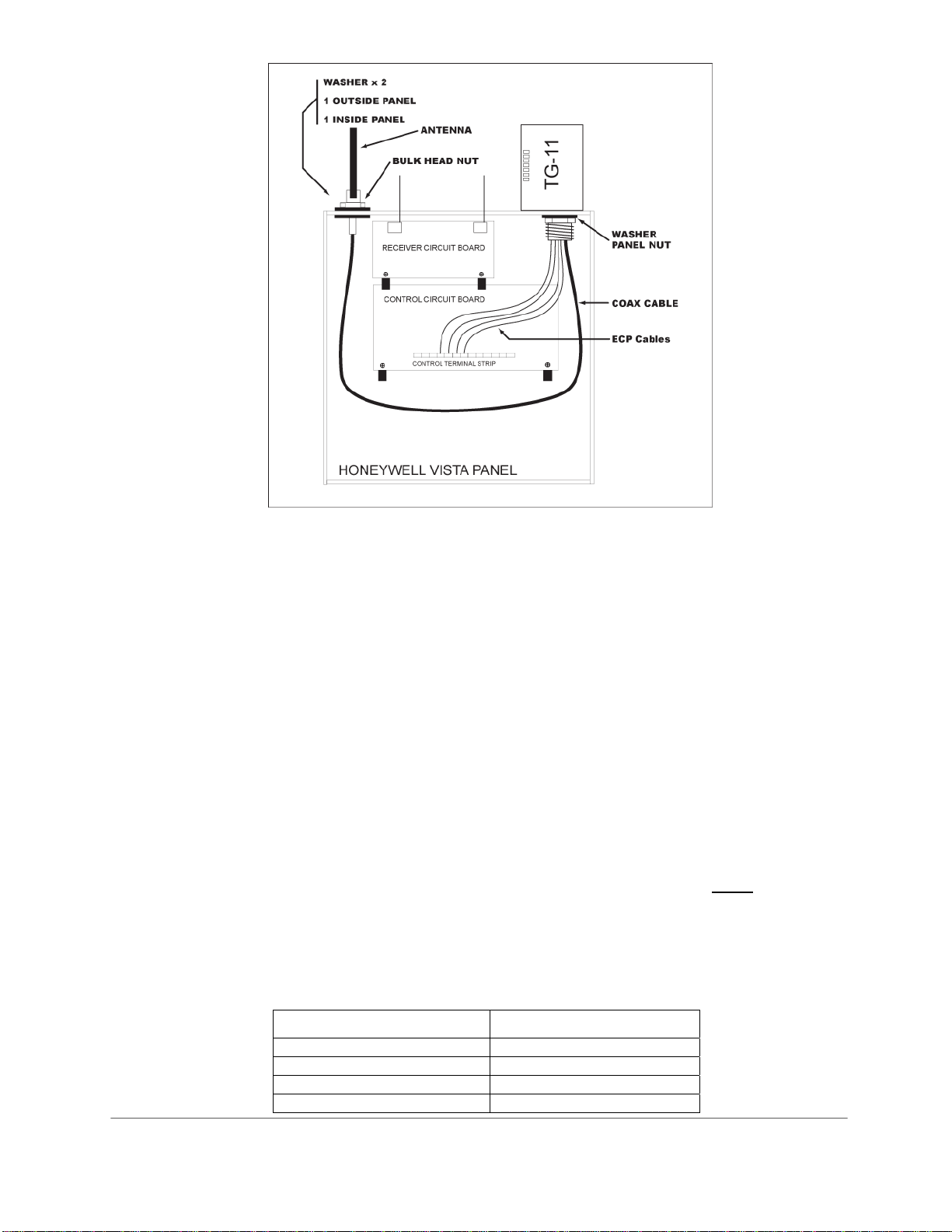
Figure 3. 3 – External Top Mount
STEP 2. Once the TG-11 is secure, a location for the antenna must be chosen. In most cases, the antenna will
be directly mounted to the cabinet. To reduce the effects of RF interference, avoid routing the antenna cable
over or under the alarm PCB or bundling it with other wires.
A. To mount the antenna directly to the cabinet, route the antenna cable to an available punch-out at
the top of the cabinet. It is recommended that the antenna ALWAYS be mounted vertically. Use
the included washers and hardware to secure the TNC antenna connector to the cabinet. Screw
the antenna to the TNC connector.
B. For a remote antenna installation, please use an approved Telular antenna extension kit (see
section A3). Please note, that the remote antenna will be connected to the TNC connector, at the
end of the factory installed antenna cable.
Note 1: Optimum RF performance can usually be found at the highest point within a building with the fewest
number of walls between the antenna and the outside of the premises.
Note 2: To avoid interference with other electronic devices operating in the area, avoid mounting the antenna
near other electronic devices.
Note 3: The TG-11 is supplied with a dipole antenna, designed for indoor installations ONLY.
STEP 3. Using the chart below, connect the ECP wires from the TG-11 to the control panel’s ECP bus. The TG-
11 must be connected directly to the panel’s terminal strip and should NOT be spliced onto existing wires.
Please refer the Power Management section to calculate the total power consumption for the system. Use
supplied worksheet as a guide.
TG-11 Control Panel
Black wire to Ground
Red wire to Power
Green wire to Input
Yellow wire to Output
56039504 08/20/2008 © 2008 Telular Corporation
3
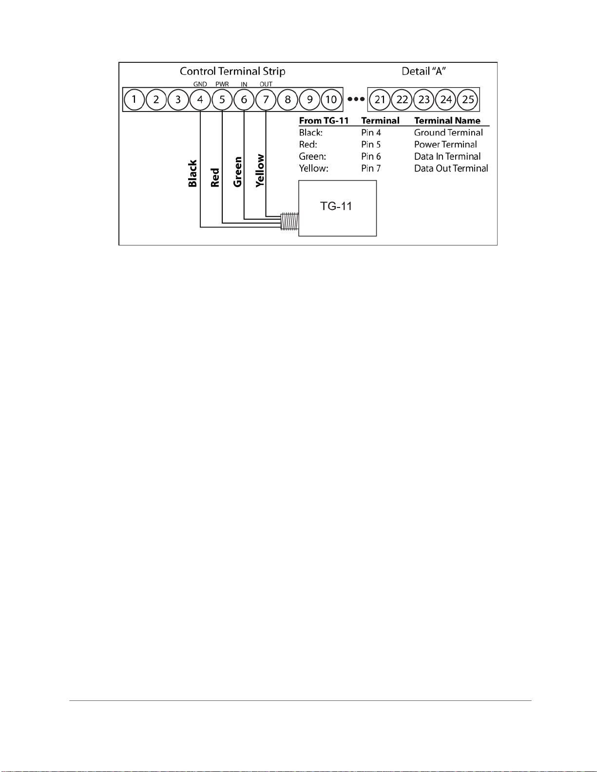
Figure 3. 4 - ECP
STEP 4. Once all the connections have been verified, power up the panel by reconnecting the power transformer
and battery. Verify that the TG-11’s power LED is lit.
STEP 5. Once power has been established to the TG-11, check the cellular signal strength using the RSSI
button. The RSSI button is used to toggle between RSSI mode and system status mode. The unit will remain in
RSSI mode for approximately 10 minutes, before reverting back to status mode. You may also press the RSSI
button to exit RSSI mode and refresh system status.
Using the Chart 6. 1 determine if the TG-11 is receiving the appropriate amount of signal.
You must have signal strength greater than -90dBm (2½ RSSI), in order for the TG-11 to function properly.
If the signal strength is too low, please try the following:
1) Verify proper antenna connection
2) Relocate the antenna
3) Replace antenna with high gain antenna
4) Relocate the antenna (using external mounting kit)
STEP 6. If proper signal has been achieved, the panel can now be programmed for use with the TG-11. Generally
speaking, the TG-11 is equivalent to Honeywell’s Long Range Radio (LRR), therefore the same programming
steps are necessary. Please refer to the panel’s “Installation and Setup Guide” for details.
If panel programming is to be done locally, then you may use a 6160, two-line alpha keypad. If the system
does not have one, then you must connect one temporarily, in order to program the panel. The installer should
also be familiar with mechanics of panel programming before attempting local programming.
The following are the basic steps for local programming of the Vista series panel:
1) Enter programming mode using the installer code (installer code + 800).
2) Activate the Long Range Radio-LRR (field *29 followed by 1).
3) Set Reporting Mode
oOnly if the TG-11 is being setup as the Primary reporting device, erase Primary/Secondary
Phone number (fields *41* and *42*), and then exit programming (*99).
oIf the TG-11 is being setup up as the Backup reporting device, set reporting mode (field *49)
then enter 0 for backup mode, and then exit programming (*99).
oIf the TG-11 is being setup up as the Split/Dual reporting device, set reporting mode (field *49)
then enter 1 - 5 for dual reporting, and then exit programming (*99).
For further details on the panel programming please refer to the manual included with the panel
56039504 08/20/2008 © 2008 Telular Corporation
4

NOTE: If TG-11 is unregistered and enabled, the panel will produce a long range radio fault upon exiting installer
mode. The following message will appear on the keypad “CHECK 103 LngRng Radio 000F”. This is normal and
expected, until the radio has been registered and activated with the Telular Communication Center.
STEP 7. If not already done, the TG-11 needs to be registered with the Telular Communication Center. To
register the unit, simply fill out the attached form (page 10) and fax it back to (678) 945-1651 or email form to
cellservice@telular.com. Please remember to complete the MANDATORY Central Station Reporting section.
For faster service, register online, at www.TelguardOnline.com or complete registration information at
www.Telguard.com.
It is highly recommended that this step be done PRIOR to going to the job site (see Installation Tip at beginning of
this section).
Once the TG-11 is registered with the Telular Communication Center, an alarm must be triggered in order to
activate the service for the first time.
Note the status of the TG-11, by using LEDs. Use Chart 6. 3 below as reference. Make sure the TG-11 is no
longer in the RSSI mode before attempting to read the status information. To toggle between modes, press the
RSSI button (this will also update status with the most recent information).
1) If a “NAK” error is received (LEDs 1 and 4 flashing), please call Telular Customer Service and verify that
the account has been registered.
2) If a “Failed Registration” error occurs (LEDs 1 – 5 flashing), verify the RSSI signal. If the RSSI is good,
call Telular Customer Service.
3) If 1 or 2 occurs, then press the RSSI button to go to RSSI mode. Leave it on that mode for 20 seconds,
then press the button again. This will reset the unit to normal status.
4) If LED 1 is on and solid, the unit been successfully installed and setup.
STEP 8. The final step is to test the TG-11 by sending a test alarm. This will authenticate the TG-11 and verify
proper communication on the cellular network. This test is also used to verify that the alarm arrives correctly at the
Central Station Monitoring Company.
WARNING: Before tripping any alarms, please make sure that the Central Station Monitoring Company is
notified of the test.
STEP 9. To clear any error being displayed at the end of this installation (e.g., “CHECK 103 LngRng Radio
000F”), enter programming mode using the installer code (installer code + 800) and then exit programming (*99).
WARNING: Before tripping any alarms, please make sure that the Central Station Monitoring Company is
notified of the test.
56039504 08/20/2008 © 2008 Telular Corporation
5

4.0 POWER MANAGEMENT
The TG-11 derives all of its power via the alarm panel’s Aux power (i.e. ECP bus). It very important to assure that
the total current, for the overall alarm installation, does not exceed the panel’s Aux power specifications (refer to
alarm panel’s Installation and Setup Guide).
TG-11 Power Requirements
•9-15v DC, 300 mA
Auxiliary Device Current Draw Worksheet (typical devices)
Device Standby
mA Peak
mA No.Units Total (stby/max)
mA
TG-11 65 250 x 1 = 65 / 250
6150 Fixed-Word Keypad 40 70 x
6160 Alpha Keypad 40 150 x
5881/5882 RF Receiver 60 - x
5883 RF Transceiver 80 - x
4229 Zone
Expander/Relay 30 100 x
4219 Zone Expander 30 - x
Additional hardwired
devices x =
x =
x =
x =
x =
Notes:
1. Max current for Auxiliary Power is 500mA (Vista ® 20P, 20PSIA, 15P, 15PSIA, 10P and 10PSIA).
2. Max current for Alarm Sounder and Auxiliary Power, combined, cannot exceed 600mA.
3. For UL Installations and Residential fire installations, please refer to battery selection chart, located in the
alarm panel’s Installation and Setup Guide.
4. For a detailed list of alarm system devices, please refer the alarm panel’s Installation and Setup Guide.
5.0 REMOTE PANEL DOWNLOADING
The TG-11 gives you the ability to send alarm signals and panel upload/download over-the-air. The installer can
remotely upload system programming that has been manually entered into the panel, or previously downloaded.
Panel downloading using the TG-11 requires the Compass Downloader software version 1.5.8.54 or higher. For a
list of supported Vista panels please refer to the Compass Downloader software manual.
For more information on panel downloading please visit http://www.telular.com/paneldownloading.
56039504 08/20/2008 © 2008 Telular Corporation
6

6.0 LED DESCRIPTIONS
6.1 SYSTEM TROUBLE CONDITIONS
Power Failure Condition (PFC)
The TG-11 monitors input DC voltage. If a low voltage is identified, (voltage below 7.2 vdc) a power failure
condition (PFC) is declared; the System Trouble Condition LED (STC LED) will flash 1 time. Upon restoration of
power, the TG-11 will restart and STC LED is returned to normal.
No Service Condition (NSC)
The TG-11 declares a no service condition (NSC) when the measured “receive” cellular radio signal strength at
the protected premises drops to -114 dBm or less; the STC LED will flash 4 times. Restoration of this condition
occurs when a measurable signal strength greater than –114 dBm is maintained for a period of time.
Radio Communications Failure Condition (RFC)
Radio communications failure condition (RFC) is declared when the TG-11 is unable to transmit over the cellular
network even with acceptable signal strength. RFC is indicated by STC LED flashing 5 times.
Panel Presence Failure Condition (PPF)
The TG-11 monitors connection to the control panel. A panel presence failure condition (PPF) is declared when
communications with the panel is lost. PPF is indicated by STC LED flashing 7 times. The PPF condition is
cleared when the panel communication's is restored. An alarm is generated to the central station when PPF is
declared and cleared.
The LEDs are used to indicate either operational status or received cellular signal (RSSI). The RSSI button is
used to toggle the mode of the LEDs.
6.2 RSSI Mode
The RSSI button on the front of the TG-11 is used to toggle RSSI mode. RSSI mode uses the LEDs to indicate
received signal strength and the number of detected cellular towers. Slowly move the antenna to achieve
maximum signal strength. Locate where the most LEDs (up to four) are lighted. The minimum RSSI is 2½, (for
additional antenna strength additional options are available.)
Chart 6. 1
LED #1 Detected Cellular Towers
on > 1
off 1
RSSI LED #2
LED #3 LED #4 LED #5 RF dBm
NO SVC off off off flash N/A
1 off off off
on <-111dBm
1 ½ off off flash on >-110 dBm
2 off off
on on >-100 dBm
2 ½ off flash on on
>-90 dBm (minimum value)
3 off
on on on >-80 dBm
3 ½ flash on on on >-70 dBm
4 on on on on >-60 dBm
LED #6 Panel Connection
on good panel connection
off incomplete panel connection
56039504 08/20/2008 © 2008 Telular Corporation
7
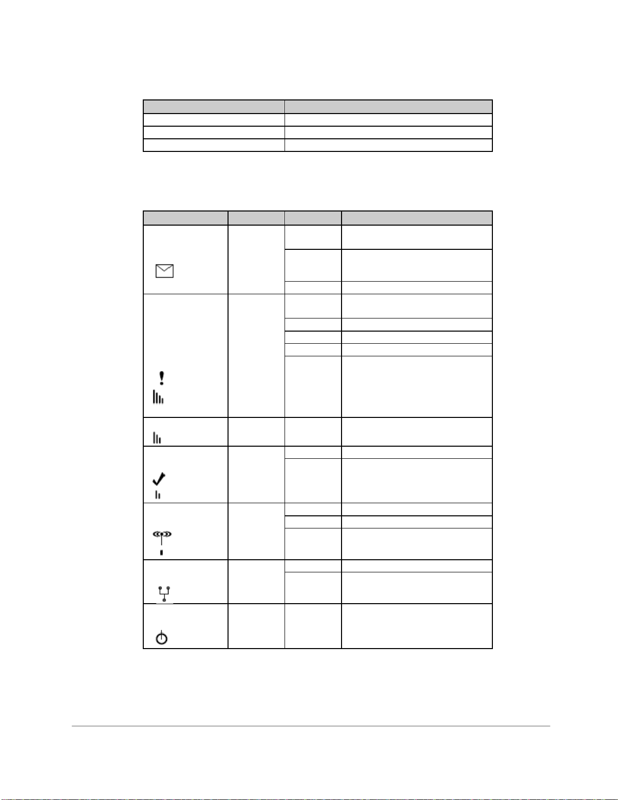
6.3 Operational Status
Registration
The LEDs provide registration indications as shown in the following table.
Chart 6. 2
System Status LEDs Registration Indications
LEDs #1 thru #5 Flashing Failed Registration /Weak Signal
LED #1 and #4 Flashing NAK - Registration Error
LED #1 On and solid Registration Successful
Functionality
7 LEDs provide an immediate visual indication of system status.
Chart 6. 3
Status LED Color State Indication
LED #1 Green on Registered and Enabled
REG
off Not Registered
flash Registered, but Disabled
LED #2 Red off Normal / No failures
System
1 flash Power Failure Condition (PFC)
Trouble
4 flash No Service Condition (NSC)
Condition
5 flash Radio Failure Condition (RFC)
(STC)
7 flash Panel Presence Failure (PPF)
LED #3
Yellow On/Off Used only in RSSI Mode
LED #4 Red on Waiting for ACK
ACK
off Idle
LED #5 Green on Initializing / Sending Data
RADIO off Idle
flash Connecting
LED #6 Red on Panel Communication
PANEL
off No Panel Communication
LED #7 Green on Power /On
POWER
off No Power
56039504 08/20/2008 © 2008 Telular Corporation
8

7.0 SYSTEM SPECIFICATIONS
Digital Cellular Radio
The Telular TG-11 radio supports GSM/GPRS cellular protocol. It is equipped with an integrated radio transceiver
conforming to all the requirements of the GSM Phase 2+ tests specified in GSM 11.10. The TG-11 transceiver is
FCC compliant, meeting all of the requirements of Part 24 and SAR testing. It is also compliant to the PTCRB
NAPRD03 requirements.
Frequency range: GSM 850/1900
Transmit Receive
850: 824MHz – 849MHz 869MHz – 894MHz
1900: 1850MHz – 1910MHz 1930Hz – 1990MHz
Antenna Port:
SMA (Female) on main PCB, 50-ohm
TNC (Female), bulkhead mount, via 24” cable, 50-ohm
Alarm Panel Communication and Models Supported:
Honeywell®/Ademco® ECP bus
Vista 20P, 20PSIA, 15P, 15PSIA, 10P, 10PSIA
Receiver Sensitivity:
–109dBm (Wireless Microprocessor WMP100 Technical Specification, WM_DEV_WUP_PTS_004)
Transmit Power:
EGSM 850 MHz: Class 4 (2 watts)
PCS 1900 MHz: Class 1 (1 watt)
Power Requirements
9-15v DC, min 300 mA via Alarm Panel Aux Power
Current Consumption
65 mA (standby)
250 mA (transmit)
Supplied Antenna:
Dipole, TNC (Male)
Physical Size and Weight:
5.0” H x 3.125” W x 1.5” D
6.1 oz
Operating Environment:
0°C to +49°C
0 - 85% humidity (non-condensing)
FCC RF Exposure Information
The external antennae used for this radio module must provide a separation of at least 8 inches (20 centimeters)
from the general public.
NOTE: Dealer Account Establishment and Cellular Activation must be complete prior to Installation (see
section A1)
56039504 08/20/2008 © 2008 Telular Corporation
9
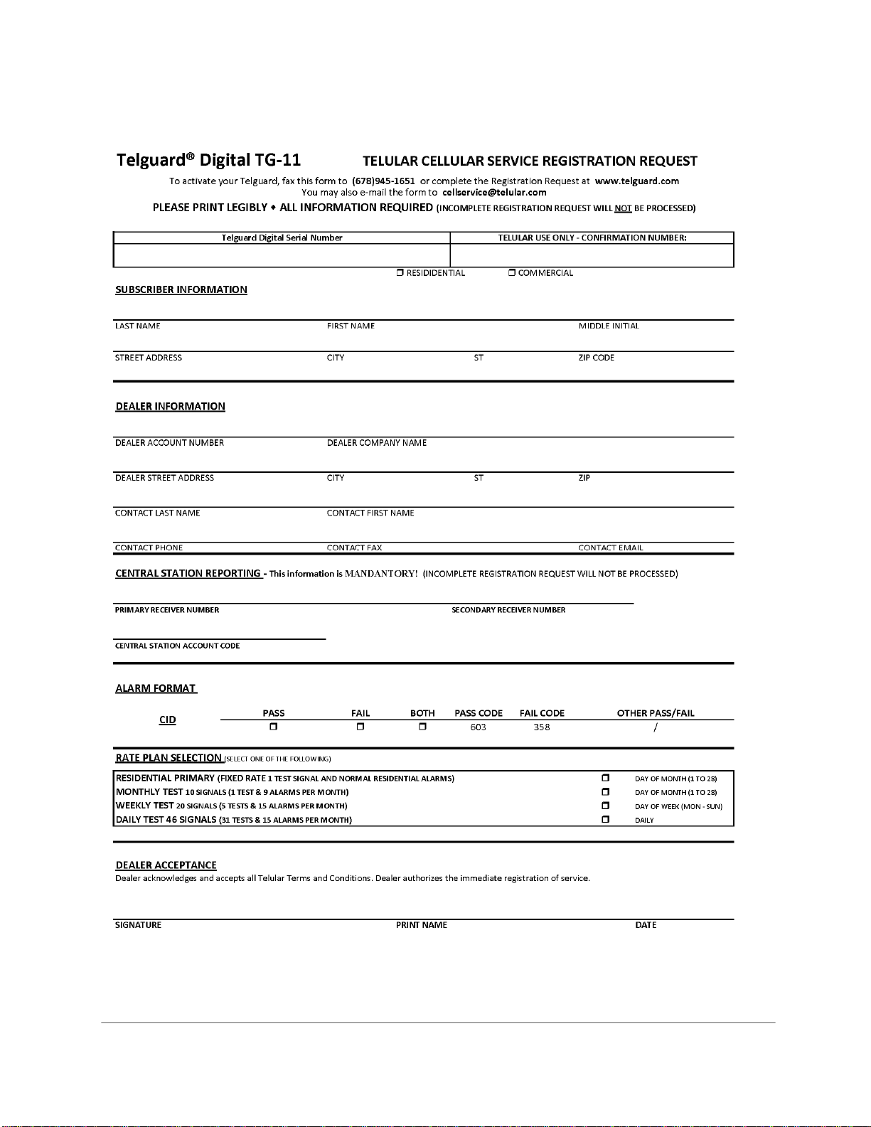
A1 ACTIVATION FORM
56039504 08/20/2008
© 2008 Telular Corporation
10

56039504 08/20/2008 © 2008 Telular Corporation
11
A2 WARRANTY
Telular will repair or replace (our option) inoperative units for up to two years from date of manufacture. This excludes
damage due to lightning or installer error. Unauthorized modifications void this warranty. Not responsible for
incidental or consequential damages. Liability limited to price of unit. This is the exclusive warranty and no other
warranties will be honored, whether expressed or implied. An RMA must be assigned by calling tech support
800-229-2326 before returning product to:
Telular Corporation
Attn: Repair Depot
1801 South Fulton Drive
Corinth, MS 38834
RMA number must be on outside of box or product will not be accepted.
A3 PARTS LIST
Part No. Description
Basic Hardware:
TG-11
Model TG11G001 Model TG11G001 (TG-11) meets the requirements for Household Burglary, Household Fire, and
Commercial Burglary installations.
TG11G001 is UL Listed for the following:
UL Household Burglary (NBSX)
UL Commercial Burglary (APAW: Police Station – Burg and AMCX: Central Station
Burg)
UL Household Fire (UTOU)
General Accessories:
ACD-12 12 feet of antenna cable and mounting bracket
ACD-35 35 feet of low loss high performance antenna cable and mounting bracket
ACD-50 50 feet of low loss high performance antenna cable and mounting bracket
ACD-100 100 feet of low loss high performance antenna cable and mounting bracket
HGD-0 High Gain Directional Antenna
EXD-0 Antenna - External with ground plane
This manual suits for next models
1
Table of contents
Other Telguard Digital Cell Phone manuals


