Tellabs 4008 User manual

•il!itellabs
technical manual
76-834008
revG
practice section
834008
©Tellabs Inc., 7September 1979
all rights reserved,
printed
in
USA
4008
Program Amplifier*
•
•
contents
section 1general description page 1
section 2application page 2
section 3installation page 4
section 4circuit description page 8
section 5block diagram page 9
section 6specifications page 8
section 7testing and troubleshooting page
10
1. general description
1.01
The
Tellabs
4008
Program
Amplifier
(fig-
ure
1)
is
asingle-channel, wideband,
low-distortion
amplifier
designed
for
use
in
program transmission
applications.
An
integral
amplitude
equalizer pro-
vides switch-selectable, adjustable, precision equal-
ization
of
non
loaded cable
for
8kHz
or
15kHz
pro-
gram cirCUits,
with
capability
of
greater than 30dB
slope
correction.
With
the
equalizer removed (also
by
switch selection),
the
amplifier
response
is
essen-
tially
flat
(± 1dB)
from
20Hz
to
20kHz.
1.02 The
4008
provides
from
0
to
40dB
of
ad-
justable gain in switch-selectable 10dB increments
(0
to
10dB, 10
to
20dB,
20
to
30dB,
or
30
to
40dB).
Within
each increment, gain
is
continuously
adjust-
able via afront-panel
potentiometer.
Maximum
out-
put
is
+20dBm.
1.03 When used
to
provide precision
amplitude
equalization in
5,
8,
or
15kHz
program
circuit
ap-
plications,
an
active equalizer
is
used
to
compen-
sate
for
the
frequency response
of
nonloaded tele-
phone cable, and equalization
is
controlled
by
ad-
justment
of
three
potentiometers
accessed
through
the
module's
front
panel.
Two
adjustments, one
for
high frequencies and one
for
low
frequencies,
es-
tablish
the
equalizer response shape. A
third
ad-
justment
provides response
"trimming"
at very
low
frequencies.
The
composite equalizer
is
capable
of
slope
correction
in excess
of
30dB
for
various
lengths and
gauges
of
nonloaded telephone cable.
Equalization
to
within
±1dB
is
achievable
for
either
8kHz
or
15kHz
circuits.
Adjustment
is
pre-
cise and can
be
accomplished
with
relative
ease.
Roll-off
is
provided
at
approximately
10kHz
in
the
lower
of
the
two
switch-selectable equalization
ranges, and
at
20kHz
in
the
higher range.
1.04 The
4008
is
designed
to
operate between
600
ohm
balanced
or
150
ohm
balanced
or
unbal-
anced source and load impedances.
Input
and
out-
put
impedances
are
each independently switch-
selectable
for
150
or
600
ohms.
Input
and
output
impedances are
not
affected
by
insertion
of
the
active
amplitude
equalizer.
1.05 Secondary
lightning
protection
is
provided
at
both
ports
of
the
Amplifier,
including
surge cur-
rent
limiting
resistors in
both
input
and
output
figure
1.
4008
Program
Amplifier
paths. Transient
protection
is
also provided
for
the
power
regulating
circuit
in
the
Amplifier.
1.06 The
4008
is
designed
to
operate on any in-
put
voltage between
-23
and
-56Vdc.
Current
drain
is
50mA
at
maximum
output
and
35mA
quiescent.
1.07
Use
of
tantalum
capacitors and
other
care-
fully
chosen components permits operation
of
the
4008
within
the temperature range
of
-40
0
to
+140
0Fahrenheit.
1.08
The
front
panel
of
the
4008
is
designed
so
that
adjustments can be made
while
the
module
is
mounted
in place. Front-panel gain and equalization
controls
are complemented
by
a
full
set
of
test
jacks
(input,
output,
input
monitor,
and
output
monitor)
to
facilitate
alignment and testing
of
the
module.
1.09 A
Type
10 module, the
4008
mounts in
one
position
of
aTellabs
Type
10
Mounting
Shelf,
versions
of
which
are
available
for
relay rack
or
apparatus
case
installation. In relay rack applica-
tions,
up
to
12 modules may be
mounted
across a
19-inch relay rack,
while
up
to
14
modules may
be
mounted
across a23-inch rack. In either
case,
6
inches
of
vertical rack space
is
used.
1.10 As amember
of
Tellabs'
248
Group
of
Pro-
gram Transmission equipment, the
4008
may also
be
mounted
in any
of
Tellabs' prewired
Type
248
Mounting
Assemblies, which
are
available in
both
apparatus-case and rack-mounted-shelf versions.
page 1*A
Tellabs
Videotape
Training
Program
is
available
for
this
product.

•
figure 3.
2488
Program
Amplifier
Assembly
labeled HF (h igh frequency) and LF
(low
frequency)
on
the
module's
front
panel. A
third
front-panel
potentiometer, labeled
LF
trim,
is
provided
to
"trim"
low-frequency (below200Hz) response after
primary
equalization
has
been achieved. Acompo-
site frequency response
for
cable and
amplifier
that
is
flat
within
±1dB
from
either 50Hz
to
15kHz
or
from
100Hz
to
8kHz
can
be
achieved
with
the
4008's equalizer.
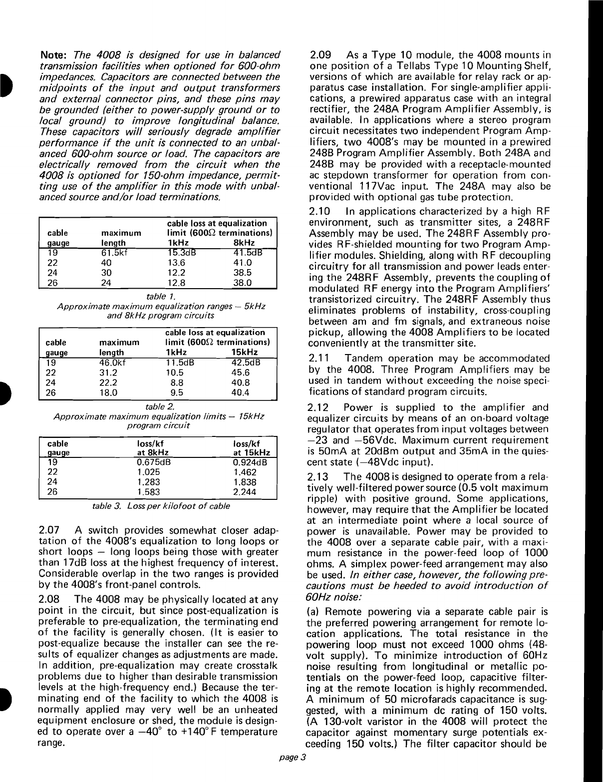
2.04 Slope equalization provided
by
the active
equalizer
is
limited
to
a
loss
differential
of
about
31
dB between lowest and highest frequencies
of
interest.
This
limit
is
translated
to
equivalent
cable lengths in tables 1and
2.
Table 3lists the
loss
per ki
lofoot
of
various
gauges
of
cable at
both
8kHz
and 15kHz.
figure
2.
248A
Program
Amplifier
Assembly
The
248A
and 248B Assemblies
are,
respectively,
single-module wall-mounted and
two-module
desk-
top
or
wall-mounted apparatus
cases
(see
figu
res
2
and 3). Aspecial wall-mounted Assembly,
the
248RF (figure 4), provides
both
mounting
and ef-
fective RF shielding
for
two
4008
modules.
Pre-
wired 19 and 23-inch relay-rack-mounted Shelf
Assemblies, the 248C through 248G,
are
also avail-
able.
Further
information
is
available in Tellabs'
practices and catalog sheets describing the 248
Assemblies and the
4012
and
4018
Program Distri-
bution
Amplifiers.
2. application
2.01 Tellabs'
4008
Program
Amplifier
module
provides
the
amplification,
amplitude equalization
and
low
harmonic
distortion
necessary
for
the
transmission
of
high
quality,
wideband audio
sig-
nals over nonloaded telephone cable. As such, the
4008
finds
primary
application
as
aprogram amp-
lifier,
conditioning
the
transmission
facility
(i.e.,
nonloaded telephone cable)
from
aradio
or
televi-
sion station
to
a
transmitter
site,
or
from
aremote
pickup
point
to
astudio
or
transmitter
site. Stan-
dard
5kHz
(am),
8kHz
(television audio),
or
15kHz
(fm)
bandwidth
signals may be accommodated.
2.02 The 0
to
40dB gain range
of
the
4008, in
conjunction
with
its
+20dBm
maximum
output
level, provides adequate
amplification
for
appli-
cations
within
the
limits
of
good transmission
de-
sign. The
four
gain
ranges
(0
to
10dB, 10
to
20dB,
20
to
30dB, and
30
to
40dB) are selected via aDIP
switch on
the
4008's
printed
circuit
board. Fine figure 4.
248RF
Program
Amplifier
Assembly
adjustment
within
each
range
is
accomplished
by
means
of
afront-panel potentiometer. Gain may be
2.05
When equalization
is
not
required, the
easily set
to
any level ±0.1 dB
within
the
overall 4008's equalization
circuitry
may
be
removed
from
o
to
40dB range.
the
transmission path via switch
option.
In this
2.03 The active equalizer in
the
4008
is
capable mode,
the
4008
provides
flat
gain
from
20Hz
to
of
inversely matching
the
slope
of
nonloaded tele-
20kHz,
with
roll-off
below 20Hz and above 20kHz.
phone cable
from
either 50Hz
to
15kHz
or
from
2.06
Equalizer response
is
unaffected
by
choice
100Hz
to
8kHz,
where
the
loss
differential
between
of
input
and
output
impedance,
but,
in general,
the lowest and the highest frequencies
of
interest
is
use
of
150-ohm cable interface impedances
will
between 0and 31dB. Equalizer response
is
indepen-
permit
equalization
of
longer cable sections than
dent
of
amplifier
gain,
permitting
independent ad- wil1600-ohm impedances. (The150-ohm impedance-
justment
of
facility
frequency response and
loss
(or
matching
option
presents
an
impedance mismatch
gain). Equalizer slope
is
matched
to
cable charac-
that
provides anominal degree
of
slope equaliza-
teristics
through
adjustment
of
two
potentiometers
tion
for
nonloaded telephone cable.)
page 2
Note: The
4008
is
designed
for
use
in balanced
transmission facilities when
optioned
for
600-ohm
impedances. Capacitors are connected between the
midpoints
of
the
input
and
output
transformers
and
external
connector
pins,
and
these
pins
may
be grounded (either
to
power-supply
ground
or
to
local ground) to improve
longitudinal
balance.
These
capacitors
will
seriously degrade
amplifier
performance
if
the
unit
is
connected
to
an unbal-
anced 600-ohm source
or
load. The capacitors are
electrically removed
from
the
circuit
when the
4008
is
optioned
for
150-ohm impedance,
permit-
ting
use
of
the
amplifier
in this mode
with
unbal-
ancedsource
and/or
load terminations.
table 2.
Approximate
maximum
equalization
limits
-
15kHz
program
circuit
2.07 Aswitch provides somewhat closer adap-
tation
of
the
4008's equalization
to
long loops
or
short loops -long loops being those
with
greater
than 17dB
loss
at
the
highest frequency
of
interest.
Considerable overlap in the
two
ranges
is
provided
by
the 4008's front-panel controls.
2.08 The
4008
may
be
physically located
at
any
point
in the
circuit,
but
since post-equalization
is
preferable
to
pre-equalization,
the
terminating
end
of
the
facility
is
generally chosen.
(It
is
easier
to
post-equalize because
the
installer
can
see
the
re-
sults
of
equalizer changes
as
adjustments are made.
In
addition,
pre-equalization may create crosstalk
problems due
to
higher
than
desirable transmission
levels at
the
high-frequency end.) Because the ter-
minating end
of
the
facility
to
which
the
4008
is
normally
applied may very well
be
an
unheated
equipment enclosure
or
shed,
the
module
is
design-
ed
to
operate over a
-40
0
to
+140
0Ftemperature
range.
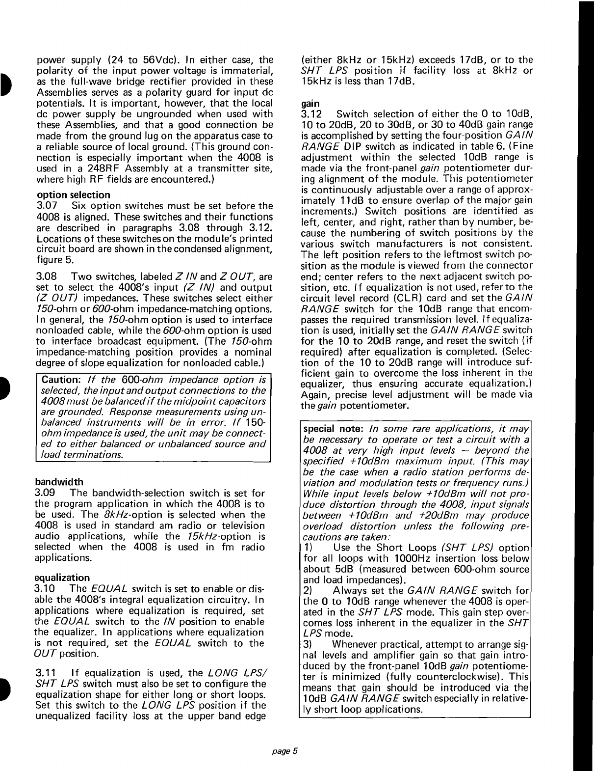
2.09 As a
Type
10
module, the
4008
mounts in
one position
of
aTellabs
Type
10
Mounting
Shelf,
versions
of
which
are
available
for
relay rack
or
ap-
paratus
case
installation.
For
single-amplifier appli-
cations, aprewired apparatus
case
with
an
integral
rectifier,
the
248A
Program
Amplifier
Assembly,
is
available.
In
applications where astereo program
circuit
necessitates
two
independent Program
Amp-
lifiers,
two
4008's may
be
mounted
in aprewired
248B Program
Amplifier
Assembly. Both
248A
and
248B may
be
provided
with
areceptacle-mounted
ac
step
down
transformer
for
operation
from
con-
ventional 117Vac input. The
248A
may also
be
provided
with
optional
gas
tube
protection.
2.10 In applications characterized
by
ahigh RF
environment, such
as
transmitter
sites, a248RF
Assembly may be used.
The
248RFAssembly pro-
vides RF-shielded
mounting
for
two
Program
Amp-
lifier
modules. Shielding, along
with
RF decoupling
circuitry
for
all transmission and
power
leads enter-
ing
the
248RF
Assembly, prevents
the
coupling
of
modulated RF energy
into
the
Program
Amplifiers'
transistorized
circuitry.
The
248RFAssembly thus
eliminates problems
of
instability,
cross-coupling
between am and
fm
signals, and extraneous noise
pickup,
allowing
the
4008
Amplifiers
to
be located
conveniently
at the
transmitter
site.
2.11 Tandem operation may
be
accommodated
by
the 4008. Three Program
Amplifiers
may
be
used
in tandem
without
exceeding the noise speci-
fications
of
standard program circuits.
2.12 Power
is
supplied
to
the
amplifier
and
equalizer circuits
by
means
of
an
on-board voltage
regulator
that
operates
from
input
voltages between
-23
and
-56Vdc.
Maximum
current
requirement
is
50mA
at
20dBm
output
and
35mA
in
the
quies-
cent state
(-48Vdc
input).
2.13
The
4008
is
designed
to
operate
from
arela-
tively
well-filtered
power
source (0.5
volt
maximum
ripple)
with
positive ground. Some applications,
however, may require
that
the
Amplifier
be
located
at
an
intermediate
point
where alocal source
of
power
is
unavailable. Power may
be
provided
to
the
4008
over aseparate cable pair,
with
amaxi-
mum
resistance in
the
power-feed loop
of
1000
ohms. Asimplex power-feed arrangement may also
be
used.
In
either
case,
however, the
following
pre-
cautions
must
be heeded
to
avoid
introduction
of
60Hz
noise:
(a)
Remote powering via aseparate cable pair
is
the
preferred powering arrangement
for
remote lo-
cation applications.
The
total
resistance in the
powering loop
must
not
exceed
1000
ohms (48-
volt
supply).
To
minimize
introduction
of
60Hz
noise resulting
from
longitudinal
or
metallic po-
tentials on
the
power-feed loop, capacitive
filter-
ing
at
the
remote location
is
highly
recommended.
A
minimum
of
50 microfarads capacitance
is
sug-
gested,
with
a
minimum
de rating
of
150 volts.
(A
130-volt varistor in the
4008
will
protect
the
capacitor against
momentary
surge potentials ex-
ceeding 150 volts.)
The
filter
capacitor shou
Id
be
page 3
loss/kf
at
15kHz
0.924dB
1.462
1.838
2.244
15.3dB 41.5dB
13.6 41.0
12.2 38.5
12.8 38.0
cable loss
at
equalization
limit (600[2 terminations)
1kHz
8kHz
11.5dB 42.5dB
10.5 45.6
8.8 40.8
9.5 40.4
cable loss
at
equalization
limit (600[2 terminations)
1kHz
15kHz
loss/kf
at
8kHz
0.675dB
1.025
1.283
1.583
maximum
length
61.5kf
40
30
24
46.0kf
31.2
22.2
18.0
maximum
length
table 3. Loss
per
kilofoot
of
cable
table
1.
Approximate
maximum
equalization
ranges -
5kHz
and
8kHz
program
circuits
19
22
24
26
19
22
24
26
cable
llauae
cable
gauge
19
22
24
26
cable
aauae
t
t
t

connected
directly
across the
power
pair at
the
remote location.
(b) Simplex leads are derived on
the
input
and
out-
put
transformers (600-ohm
option
only)
to
accom-
modate simplex powering
at
remote locations.
This
powering arrangement
is
not
recommended, how-
ever, because
of
the
likelihood
of
noise problems.
If
simplex powering
is
to
be
used, acapacitive
fil-
ter
should
be
used between the simplex lead and
the
return path
(or
ground,
if
ground return
is
used), and care must
be
taken
to
ensure
that
the
simplex current
is
balanced (no more than
3mA
of
dc unbalance can be tolerated). Acapacitor
of
at
least
50
microfarads,
with
minimum
150
volt
rat-
ing, should be
used
for
power
filtering.
(c) When
the
4008
is
powered via aseparate cable
pair at aremote location, several grounding arrange-
ments are available
to
minimize
introduction
of
60Hz
noise. These include
optional
grounding
of
the
transformer
midpoint
capacitors
to
either
local
ground
or
to
supply ground,
optional
ground
of
transformer shields
to
either
ground, and provision
of
aseparate ground connection
for
the
front-panel-
mounted jack
sleeves.
If
60Hz
noise
pickup
is
noted at aremote
Amplifier
site, asystematic
"trial
and
error"
approach
to
grounding
is
recommended.
2.14
The
4008's
input
and
output
ports
may be
accessed
via
input
and
output
jacks located on
the
module's
front
panel. The jacks labeled
input
and
output
directly
access
the
Amplifier
ports,
with
the external connections opened
while
a310-Type
plug
is
inserted. I
nput
and
output
monitor
jacks,
labeled in
mon
and
out
mon, are also provided
for
bridging
access
to
the
two
ports, and,
with
a
sec-
ond plug inserted
into
the
access
jack,
the
external
facility
leads
may
be
accessed
through
the
appro-
priate
monitor
jack.
Note:
When
access
is
made to the
input
or
output
of
the amplifier through the
input
or
output
jacks,
the current-limiting resistors
are
bypassed. This will
cause
input
and
output
impedances to appear 11.2
ohms lower than will be measured
at
the input and
output
connector pins, creating aO.1dS difference
in insertion loss with a600-ohm termination and a
O.2dS difference with a150-ohm termination.
3. installation
inspection
3.01 The
4008
Program
Amplifier
moduleshould
be visually inspected upon arrival in
order
to
find
possible damage incurred
during
shipment.
If
dam-
age
is
noted, aclaim should
immediately
be filed
with
the
carrier.
If
stored,
the
module should
be
visually inspected again
prior
to
installation.
mounting
3.02 The 4008 module
mounts
in one position
of
aTellabs
Type
10 Shelf
or
Type
248
Mounting
Assembly,
both
of
which
are
available in configura-
tions
for
both
relay rack and apparatus
case
installa-
tion.
The
4008
plugs physically and electrically in-
page 4
to
a56-pin connector at
the
rear
of
the module's
mounting
position.
For
installation
of
a248
Assem-
bly,
refer
to
the
practice, schematic,
or
wiring draw-
ing available on
that
Assembly.
installer connections
3.03
Before making any connections
to
the
mounting
shelf
or
assembly, make sure
that
power
is
off
and modules
are
removed. Modules should
be
put
into
place
only
after
they
are
properly op-
tioned
and
after
wiring
is
completed.
3.04
Table 4fists external connections
to
the
4008
Program
Amplifier.
All
connections are made
via wire wrap at
the
56-pin connector
at
the rear
of
the
module's
mounting
position. Pin numbers
are
found
on
the
body
of
the
connector. In
the
case
of
the
248A
and 248RF Assemblies, external connec-
tions
are
indicated on
the
248A
and 248RF Assem-
blies, and
the
248B Assembly should
be
connected
as
per table
5.
connect:
to
pin:
AMPLIFIER
INPUT (TIP) 7
AMPLIFIER
INPUT (RING) 13
INPUT SIMPLEX 9
and
11
INPUT SX CAPACITOR GROUND
21
SLEEVE GROUND (front-panel jacks) 55
AMPLIFIER
OUTPUT (TIP) 5
AMPLIFIER
OUTPUT (RING) 15
OUTPUT
SI
MPLEX 1
and
3
OUTPUT
SX
CAPACITOR GROUND
19
SHIELD GROUND (transformer) 23
-BATT
(-23
to
-56Vdc
input) 35
GND (ground)
.,
17
table
4.
External connections to
4008
module
mounted
in Type 10
Shelf
connect:
to
terminal block position:
AMP 1
(Jl)
in 1
and
2
AMP 1(J1)
out
.4
and
5
SX
IN ,3
AMP 2(J2) in 6
and
7
AMP 2(J2)
out
9
and
10
power in
(-)
24Vdc or 18Vac
input
-
power in (+) 24Vdc or 18Vac
input
+
SX
OUT
8
ground ground lug
on
case
table 5. External connections
to
terminal
block
on
2488
Assembly
ground connections
3.05
When
the
4008
is
located in acentral
office
or
at alocation
with
local power, best results
will
be
ach
ieved when
the
transformer
sh
ield grounds
are
connected
to
the
power-supply ground.
The
jack
sleeves
may be grounded
either
to
frame ground
or
to
power
ground.
At
remote locations, the jack
sleeves
may be connected
to
local ground
or
left
open, and
the
other
grounds should be connected
eitherto
local ground
orto
power
ground, whichever
minimizes
introduction
of
60Hz
noise.
3.06
If
the
4008
is
to
be
mounted in a248A,
248B,
or
248RF Assembly,
power
may be supplied
via
an
ac
power transformer
(6VA)
or
via alocal de
t
t
t
power supply (24
to
56Vdc).
In
either
case,
the
polarity
of
the
input
power
voltage
is
immaterial,
as
the
full-wave bridge
rectifier
provided in these
Assemblies
serves
as
a
polarity
guard
for
input
dc
potentials. It
is
important,
however,
that
the
local
dc power supply
be
ungrounded when
used
with
these Assemblies, and
that
agood connection be
made
from
the ground lug on
the
apparatus
case
to
areliable source
of
local ground. (This ground con-
nection
is
especially
important
when
the
4008
is
used
in a248RFAssembly at a
transmitter
site,
where high RF fields
are
encountered.)
option
selection
3.07 Six
option
switches must be set before
the
4008
is
aligned. These switches and
their
functions
are
described in paragraphs 3.08
through
3.12.
locations
of
these switcheson the moduIe's printed
circuit
board
are
shown in
the
condensed alignment,
figure
5.
3.08
Two
switches, labeled Z
IN
and Z
OUT,
are
set
to
select the 4008's
input
(Z
IN)
and
output
(Z
OUT) impedances. These switches select
either
150-ohm
or
600-ohm impedance-matching options.
In general, the 150-ohm
option
is
used
to
interface
nonloaded cable, while
the
600-ohm
option
is
used
to
interface broadcast equipment. (The 150-ohm
impedance-matching position provides anominal
degree
of
slope equalization
for
nonloaded cable.)
ICaution:
If
the 600-ohm impedance option
is
selected, the inputand
output
connections to the
4008
must
bebalanced
if
the midpointcapacitors
are
grounded. Response measurements using un-
balanced instruments will be in error.
If
150-
ohmimpedance
is
used, the unit
may
be
connect-
ed
to either balanced or unbalanced source and
load terminations.
bandwidth
3.09 The bandwidth-selection switch
is
set
for
the program application in which
the
4008
is
to
be
used.
The
8kHz-option
is
selected when
the
4008
is
used
in standard
am
radio
or
television
audio applications, while
the
15kHz-option
is
selected when
the
4008
is
used
in
fm
radio
applications.
equalization
3.10
The EQUALswitch
is
set
to
enable
or
dis-
able the 4008's integral equalization
circuitry.
In
applications where equalization
is
required, set
the
EQUAL
switch
to
the
IN
position
to
enable
the equalizer. In applications where equalization
is
not
required, set
the
EQUAL
switch
to
the
OUT
position.
3.11
If
equalization
is
used, the
LONG
LPSI
SHT
LPS switch must also be set
to
configure
the
equalization
shape
for
either long
or
short loops.
Set this switch
to
the
LONG
LPS position
if
the
unequalized
facility
loss
at
the
upper band
edge
page
5
(either
8kHz
or
15kHz) exceeds 17dB,
or
to
the
SHT
LPS position
if
facility
loss
at
8kHz
or
15kHz
is
less
than 17dB.
gain
3.12
Switch
selection
of
either
the
0
to
10dB,
10
to
20dB,
20
to
30dB,
or
30
to
40dB gain range
is
accomplished
by
setting
the
four-position
GAIN
RANGE
DIP switch
as
indicated in table 6. (Fine
adjustment
within
the selected 10dB range
is
made via
the
front-panel gain
potentiometer
dur-
ing alignment
of
the
module. This
potentiometer
is
continuously
adjustable over arange
of
approx-
imately
11dB
to
ensure overlap
of
the
major
gain
increments.) Switch positions
are
identified
as
left,
center, and right, rather than
by
number,
be-
cause
the
numbering
of
switch positions
by
the
various switch manufacturers
is
not
consistent.
The
left
position refers
to
the
leftmost
switch po-
sition
as
the
module
is
viewed
from
the
connector
end; center refers
to
the
next
adjacent switch po-
sition,
etc. If equalization
is
not
used, refer
to
the
circuit
level record
(elR)
card and set
the
GAIN
RANGE
switch
for
the
10dB range
that
encom-
passes
the required transmission level. If equaliza-
tion
is
used,
initially
set the
GAIN
RANGE
switch
for
the
10
to
20dB range, and reset
the
switch
(if
required)
after
equalization
is
completed. (Selec-
tion
of
the
10
to
20dB range
will
introduce suf-
ficient
gain
to
overcome
the
loss
inherent in
the
equalizer, thus ensuring accurate equalization.)
Again, precise level adjustment
will
be
made via
the
gain potentiometer.
special note:
In
some
rare
applications,
it
may
be
necessary to operate
or
test acircuit with a
4008
at
very high input levels -
beyond
the
specified +10dBm maximum input. (This
may
be the
case
when aradio station performs
de-
viation and modulation tests or frequency runs.)
While
input
levels
below
+10dBm will
not
pro-
duce distortion through the 4008,
input
signals
between +10dBm and +20dBm
may
produce
overload distortion unless the following pre-
cautions
are
taken:
1)
Use
the
Short
loops
(SHT
LPS)
option
for
all loops
with
1000Hz insertion
loss
below
about
5dB (measured between 600-ohm source
and load impedances).
2) Always set
the
GAIN
RANGE
switch
for
the
0
to
10dB range whenever
the
4008
is
oper-
ated in
the
SHT
LPS mode. This gain step over-
comes
loss
inherent in
the
equalizer in the
SHT
LPS mode.
·3) Whenever practical,
attempt
to
arrange
sig-
nal levels and
amplifier
gain
so
that
gain
intro-
.duced
by
the
front-panel 1
OdB
gain
potentiome-
ter
is
minimized
(fully
counterclockwise). This
means
that
gain should
be
introduced via the
10dB GA
IN
RANGE
switch especially in relative-
ly
short
loop
applications.

*as viewed
from
connector
end
of
module
gain range left*
center*
right*
far
right*
0-10dS
on/closed
on/closed
on/closed
unused
10-20dS
off/open
on/closed
on/closed
unused
20-30dS
off/open
off/open
on/closed
unused
30-40dS
off/open
off/open
off/open
unused
table 6. SWitch se/ectlon
of
gam ranges
Note:
Only
three
of
the
four
positions
on
the
GAIN
RANGE
switch
are used. The
switch
posi-
tion
on
the far
right
is unused.
alignment
3.13
The
alignment procedure consists
of
send-
ing test tones
from
the
originating end
of
the
cir-
cuit
to
the
4008, measuring
the
level
of
each
tone
at
the
4008
with
atest set, and adjusting
the
mod-
ule's equalizer and
amplifier
appropriately. In tan-
dem applications (i.e., more than one
4008
module
in
the
circuit),
there are
two
accepted methods
of
alignment. In
the
first
method,
each
4008
is
isolat-
ed
and aligned
individually.
Test tones
are
sent
from
the
originating end
of
the
circuit
to
the
first
4008
and
that
module
is
aligned. The
next
4008
is
aligned
to
test tones sent
from
the
site
of
the
first
4008. Subsequent 4008's
are
aligned in similar
fashion. In
the
second
method
of
alignment, test
tones are sent
only
from
the
originating end
of
the
circuit
and
each
4008
is
aligned
to
those tones,
be-
ginning
with
the
4008
closest
to
the
originating
end
of
the
circuit.
In
both
methods, alignment
of
the
composite
circuit
is
verified via end-to-end
measu
rements.
Note:
Acondensed alignment procedure (figure
5)
is
included
to
facilitate alignment
of
the 4008.
alignment -
without
equalization
3.14
After
all options (including gain range) have
been selected, insert
the
4008
into
its mounting,
adjust the gain
potentiometer
fully
counterclock-
wise, and apply power.
Adjust
the gain
of
the
Amplifier
as
described in paragraph 3.17.
alignment -
with
equalization
3.15
After
all
options
have
been selected, insert
the
4008
into
its
mounting
position.
Adjust
the
HF,
LF,
and gain potentiometers
fully
counter-
clockwise and adjust
the
LF
trim
potentiometer
to
the
approximate
midpoint
of
its range.
Apply
pow-
er and
perform
the
equalization and gain alignment
procedures in paragraphs 3.16 through 3.18.
Note:
For
convenience, the
following
equalization
procedure
is
written
with
regard to the module's
use
in
15kHz applications. In
8kHz
applications,
the equalization procedure
is
identical
except
for
the frequencies
at
which level measurements are
made.
In
15kHz applications, measurements are
made
at
15kHz, 10kHz, 1000Hz,
and
100Hz. In
8kHz
applications, measurements are made
at
8kHz,
5kHz,
1000Hz,
and
100Hz.
3.16
To
align the 4008's equalizer,
it
is
essen-
tial
that
the
procedures be
followed
precisely
and in
the
order presented.
Other
procedures
will
result in failure
to
converge
on
the
desired
equalization characteristics.
page 6
A.
With a
properly
terminated transmission
measuring set (TMS) (receive) connected
to
the
4008's
output
jack, request personnel at the
originating end
of
the
circuit
to
send
15kHz
test tone at the level specified on
their
circuit
level record (CLR) card.
Verify
that
15kHz
is
being sent and record the received level.
B.
Request personnel at
the
originating end
to
send
10kHz tone at the specified level.
Verify
the
frequency and adjust the
HF
potentiometer
clockwise
until
the
10kHz level
is
equal
to
the
15kHz level recorded in step A.
C.
Request
that
the
originating end again
send
15kHz tone.
Verify
the frequency
and
record the level. Request
the
originating end
to
send
10kHz and adjust the HF potentiometer
until
the 10kHz level
is
equal
to
the new 15kHz
level. Repeat this step
until
the 15kHz and
10kHz levels
are
equal.
Be
sure
to
record
each
level. (As the HF
potentiometer
is
adjusted
clockwise,
both
the 10kHz
and
15kHz levels
will
change. Therefore, several repetitions
of
adjustment
and
measurement between 15kHz
and
10kHz
will
probably
be required to achieve
the desired
flat
response between the
two
frequencies.)
D.
Request personnel at
the
originating end
to
send
1000Hz tone at
the
specified level.
Verify
the frequency and adjust the
LF
potentiometer
clockwise
until
the
1000Hz level
is
equal
to
the
10kHz level achieved in step
C.
E.
Request that
the
originating end
send
10kHz tone.
Verify
the frequency and record
the
level.
If
the 10kHz level
is
different
from
the
10kHz level achieved in step
C,
request the
originating end
send
1000Hz and adjust the
LF
potentiometer
until
the 1000Hz level
is
equal
to
the 10kHz level. Repeat this step
until
the
1000Hz and 10kHz levels
are
equal.
Be
sure
to
record
each
level.
F.
Request
that
the
originating end
send
15kHz tone.
Verify
the frequency and record
the level. Request
that
the originating end
send
10kHz and
trim
the
HF
potentiometer
until
the
10kHz level
is
equal
to
the 15kHz level
measu
red
in
th
is
step.
G.
Request the originating end
to
send
1000Hz
and adjust
the
LF potentiometer u
nti
Ithe
1000Hz level
is
equal
to
the 10kHz level achiev-
ed
in step
F.
Record this level.
H.
Request that
the
originating end
send
100Hz tone.
Verify
the frequency, and adjust
the
LF
trim
potentiometer
until
the
100Hz
level
is
equal
to
the
1000Hz level recorded in
step
G.
I.
Request the originating end
to
send
100Hz
and 15kHz tones at the specified level.
Verify
the frequencies and
verify
that
both
levels
are
within
±1dB
of
the 1000Hz level recorded in
step
G.
continued,
page 8

tfigure
5.
Condensed alignmentprocedure
Note: These instructions coincide with the summary
of
Tellabs' 4008 Videotape Training
Program.
This and other Tellabs
Training Programs
are
available in
%"
and j2" videotape formats. Contact your Tellabs representative through your training
orengineering departments for information about this
Program.
page 7
20
Check
50Hz
and
15kHz
levels.
Recheck
the
equalization
character-
istic. Have
50Hz
and
15kHz
tones
sent. Verify
the
frequencies
and
re-
cord
each level. If
these
levels
match
within
±1
dB,
the
equalizer
is
correct-
lyaligned.
21
Frequency
Run.
Have
test
tones
sent
from
50Hz
to
15kHz
at
100Hz
intervals. Levels
should
be within
±ldB
of
the
1000Hz
level. Remove
all
test
connections;
alignment
is
completed.
14
Readjust
10kHz
and
15kHz
levels. Have 15kHz
tone
sent. Verify
the
frequency
and record
the
level.
Have 10kHz
tone
sent. Verify
the
frequency
and
record
the
level. If
the
levels are
different,
adjust
the
HF
potentiometer
until
the
10kHz
level
is
equal
to
the
15k
Hz
level. ®
15
Readjust
1000Hz
level. Have
1000Hz
tone
sent
and
verify
the
fre-
quency.
If
the
1000Hz
level
is
not
equal
to
the
10kHz
level achieved
in
step
14,
adjust
the
LF
potentiometer
until
the
1000Hz
level
is
equal
to
the
10kHz
level. Record
this
1000Hz
level.
16
Send
100Hz
tone.
Have
100Hz
tone
sent.
Verify
that
100Hz
tone
is
being sent, and
...
17
Adjust
100Hz
level
to
1000Hz
level via LF trim.
Adjust
the
LF trim
potentiometer
until the
100Hz
level
is
equal
to
the
1000Hz
level achieved
instep
15. ®
18
Compare
100Hz
and
15kHz
levels. Have
100Hz
and
15kHz
tones
sent. If
these
levels are within
±ldB
of
the
1000Hz
level
recorded
in
step
15,
the
equalizer
is
correctly
adjusted.
19
Set
1000Hz
level via gain
switches
and
control.
Refer
to
the
CLR card
for
the
required transmis-
sion level. Reset
the
GAIN
RANGE
switch (if necessary)
for
the
ap~o
priate 10dB range (see table 6). A
Have
1000Hz
tone
sent. Verify t e
frequency
and
adjust
the
gain
poten-
tiometer
clockwise until
the
re~red
transmission level
is
achieved. ®
®
12
Adjust
1000Hz
level
to
10kHz
level via LF
control.
Adjust
LF
poten-
tiometer
clockwise until
the
1000Hz
level
is
equal
to
t~
10kHz
level
achieved
in
step
10.
\SJ
13
Repeat until 1000Hzlevel equals
10kHz. Have
10kHz
tone
sent
again,
verify
the
frequency,
and
record
the
level. Have
1000Hz
tone
sent. Verify
the
frequency
and
adjust
the
LF
po-
tentiometer
until
the
1000Hz
level
is
equal
to
the
10kHz
level. Several
rounds
of
measurement
and
adjust-
ment
may be required. ©
11
Send
1000Hz
tone.
Verify
that
1000Hz
is
being
sent,
and
...
7
Send
10kHz
tone.
Verify
that
10kHz
tone
is
being sent,
and
...
8
Adjust
10kHz
level
to
15kHz
level
via HF
control.
Adjust
HF
potentio-
meter
clockwise until level
at
10kHz
is
equal
~
15kHz
level recorded
in
step
6. ®
9
Recheck
15kHz
level. Have
15kHz
tone
sent
again
and
record
the
level.
If
15kHz
level has changed, have
10kHz
tone
sent
again
and
adjust
HF
potentiometer
until
the
10kHz
level
is
equal
to
the
new
15kHz
level. ®
10
Repeat
procedure
until
10kHz
and
15kHz
levels
match.
Repeat
step 9. Several
rounds
of
measure-
ment
and
adjustment
may be requir-
ed
to
match
10kHz
and
15kHz
levels.
Z
IN
l~roo600
LONG[OO5HT
83-4008
LP5
~
LP5
15KHz
8KHz
53
[§]
S;[OO¥
EOL
55~O
[00
56
Et1
~~6
-J_O
ON""
150
rn
600
<i
~
-
Z
OUT
®
program
amplifier
4008
o
6
"e,
,,,.,,"
,~O
o
Th
is
condensed
procedure
is
provided
to
facilitate alignment
of
the
4008.
The
alignment procedure is
written
with regard
to
the
module's
use
in
15kHz
applications. In
8kHz
appli-
cations,
the
procedure
is
essentially
the
same
except
for
the
frequencies
at
which level
measurements
are made.
When aligning
the
4008
for
8kHz
ap-
pi
ications (television audio
or
am radio),
level measurements are made
at
8kHz,
5kHz, 1000Hz, and 100Hz. Refer
to
the
CLR card
for
the
required
input
and
output
impedances and
the
requir-
ed transmission level.
After
all
options
have been selected (paragraphs
3.07
through
3.12),
perform
each step
in
numeric order. Detailed alignment in-
structions
are provided in paragraphs
3.13
through
3.18.
1Gain switches set
to
10
to
20dB
rang~
See paragraph
3.12
and
table
6. ®
2HF, LF,
and
GAIN
~n~ls~IIY
counterclockwise. ®
\SJ
\Q)
3LF TRIM
control
to
middle. ®
4
Connect
test
set
to
4008
output
jack. Use a
prop~y
terminated
TMS
set for receive. ®
5Send
15kHz
tone.
Request
the
originating
end
of
the
circuit
to
send
15kHz
test
tone
at
the
level specified
in
the
CLR.
6Record 15kHz level
at
4008.
Verify
that
15kHz
tone
is
being
sent
and
re-
cord
the
received level.
~
~
page 8
specifications
continued
on
page
10
15kHz channel
5dBrN
12
22
24
noise
maximum
output
noise measured with
input
terminated,
flat
weighting,
40Hz
to
15kHz,
is
dependent
upon
ampli-
fier gain as follows:
gain
8kHz
channel
10dB 5dBrN
20dB 10
30dB 20
40dB 20
6. specifications
I
amplifier
section I
gain range
o
to
40dB
in
increments
of
10dB,
gain
continuously
adjustable within each
10dB
range
frequency response (any gain setting,
no
equalization)
±1.0dB, re
1000Hz,
20Hz
to
15kHz
±0.5dB, re
1000Hz,
30Hz
to
15kHz
gain stability
maximum
deviation
from
gain
at
70°F
is
±0.7dB,
_40°
to
+140°F,
20Hz
to
20kHz
maximum
output
level
+20dBm,
30Hz
to
20kHz;
+18dBm, 20Hz
to
20kHz
maximum
input
level (input stage overload point)
+10dBm,
30Hz
to
20kHz
(see
note,
page 5)
distortion
less
than
0.25%
THO,
50Hz
to
15kHz, measured
at
+18dB
output
level;
gain linearity
less
than
0.1 dB compression,
20Hz
to
20kHz,
any
output
level
below
+18dBm
envelope delay
less
than
15ps,
200Hz
to
20kHz
less
than
70ps,
100Hz
to
20kHz
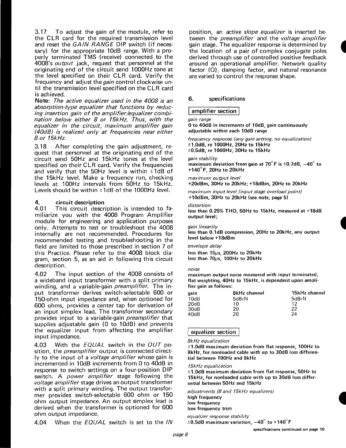
positIOn,
an
active slope equalizer
is
inserted
be-
tween the
preamplifier
and
the
voltage
amplifier
gain stage. The equalizer response
is
determined
by
the location
of
apair
of
complex conjugate poles
derived through
use
of
controlled positive feedback
around
an
operational amplifier. I\letwork
quality
factor
(Q),
damping factor, and natural resonance
are varied
to
control
the response
shape.
Iequalizer section I
8kHz
equalization
±1.0dB
maximum
deviation
from
flat
response, 100Hz
to
8kHz,
for
nonloaded
cable with
up
to
30dB
loss differen-
tial
between
100Hz
and
8kHz
15kHz equalization
±1.0dB
maximum
deviation
from
flat
response, 50Hz
to
15kHz,
for
nonloaded
cable with
up
to
30dB
loss differ-
ential
between
50Hz
and
15kHz
adjustments
(8
and
15kHz equalizers)
high
frequency
low
frequency
low
frequency
trim
equalizer response stability
±0.5dB
maximum
variation,
_40
0
to
+140°
F
4.
circuit
description
4.01 This
circuit
description
is
intended
to
fa-
miliarize you
with
the
4008
Program
Amplifier
module
for
engineering and application purposes
only.
Attempts
to
test
or
troubleshoot
the
4008
internally
are
not
recommended. Procedures
for
recommended testing and troubleshooting in the
field
are
limited
to
those prescribed in section 7
of
this Practice.
Please
refer
to
the
4008
block
dia-
gram, section 5,
as
an
aid in
following
this
circuit
description.
4.02 The
input
section
of
the
4008
consists
of
awideband
input
transformer
with
a
split
primary
winding, and avariable-gain preamplifier. The in-
put
transformer derives switch-selectable
600
or
150-ohm
input
impedance and, when optioned
for
600
ohms, provides acenter
tap
for
derivation
of
an
input
simplex lead. The transformer secondary
provides
input
to
avariable-gain
preamplifier
that
supplies adjustable gain (0
to
10dB) and prevents
the equalizer
input
from
affecting the
amplifier
input
impedance.
4.03
With
the EQUAL switch in
the
OUT
po-
sition,
the
preamplifier
output
is
connected direct-
ly
to
the
input
of
avoltage
amplifier
whose gain
is
incremented in 10dB increments
from
0
to
40dB in
response
to
switch settings on afour-position DIP
switch. A
power
amplifier
stage
following
the
voltage
amplifier
stage
drives
an
output
transformer
with
a
split
primary
winding. The
output
transfor-
mer provides switch-selectable
600
ohm
or
150
ohm
output
impedance.
An
output
simplex lead
is
derived when the transformer
is
optioned
for
600
ohm
output
impedance.
4.04 When the
EQUAL
switch
is
set
to
the
IN
3.17
To
adjust
the
gain
of
the
module, refer
to
the
CLR card
for
the
required transmission level
and reset
the
GAIN
RANGE
DIP switch
(if
neces-
sary)
for
the
appropriate 10dB range.
With
apro-
perly terminated
TIVIS
(receive) connected
to
the
4008's
output
jack, request
that
personnel at
the
originating end
of
the
circuit
send 1000Hz
tone
at
the
level specified
on
their
CLR card.
Verify
the
frequency and adjust
the
gain
control
clockwise un-
til
the
transmission level specified on
the
CLR card
is
achieved.
Note: The active equalizer used
in
the
4008
is
an
absorption-type
equalizer
that
functions
by
reduc-
ing insertion gain
of
the
amplifier/equalizer
combi-
nation
below
either
8
or
15kHz. Thus,
with
the
equalizer
in
the
circuit,
maximum
amplifier
gain
(40dB)
is
realized
only
at
frequencies near
either
8
or
15kHz.
3.18
After
completing
the
gain adjustment,
re-
quest
that
personnel at
the
originating end
of
the
circuit
send
50Hz and
15kHz
tones at
the
level
specified on
their
CLR
card.
Verify
the
frequencies
and
verify
that
the
50Hz level
is
within
±1dB
of
the
15kHz level. Make afrequency run, checking
levels at 100Hz intervals
from
50Hz
to
15kHz.
Levels should
be
within
±1dB
of
the
1000Hz level.
INPUT
MON
INPUT
5.6
(TI:)~
600
AMPLIFIER
INPUT
13
~
56
(RING
,\AA,-!
IGAIN!
OUT
i------'Wv-----
,a'
r
'1,al
I
I}
GAIN
~
RANGE
OUTPUT
MON
55
SLEEVE
OUTPUT GROUND
5
(TIP)
AMPLIFIER
OUTPUT
15
(RING)
0)
~
'll
Q.
REFERENCE
I)
~~IELD
VOLTAGE
GROUND
~7~1~C~X
t1
21
ET0.33pFd
INPUT
~<----------
SX CAPACITOR
GROUND
~
14
•I
~~g~~iOR
-V
£Elllil
SLOPE I
Ooc:
.~
EQUALIZER
1
OUTPUT
SIMPLEX
r~"
'
:,
-----------t)
OUTPUT
SX CAPACITOR
GROUND
4008
Program
Amplifier 834008
5.
Block
Diagram
~
~
~
page
70
weight
13
ounces (368 grams)
specifications
continued
from
page 8
I
common
specifications
(with
or
without
equalizer) I
input
impedance
600
ohms
±5%,
balanced, 20Hz
to
20kHz
150
ohms ±15%, balanced, 20Hz
to
20kHz
output
impedance
600
ohms ±5%, balanced, 20Hz
to
20kHz
150 ohms ±15%, balanced, 20Hz
to
20kHz
longitudinal balance (input and
output)
greater
than
65dB, 20Hz
to
20kHz
maximum
input
voltage
-56Vdc
minimum
input
voltage (for +20dBm
output
level)
-23.5Vdc
minimum
input
voltage (for +78dBm
output
level)
-20.5Vdc
current (quiescent)
30
to
35mA
at
48Vdc
current (+20dBm
output
level)
45
to
50mA
at
48Vdc
jack configuration
input monitor
output
monitor
input access
output
access
operating environment
-40°
to
+140°F
(_40°
to
+60°C), humidity
to
95% (no
condensation)
dimensions
5.58"
114.17cm) high
1.42"
(3.61cm) wide
5.96"
(15.14cm) deep
mounting
relay rack
or
apparatus case
via
one
position
of
aTellabs
Type 10 Shelf,
or
one position
of
aTellabs Type
248
Mounting Assembly
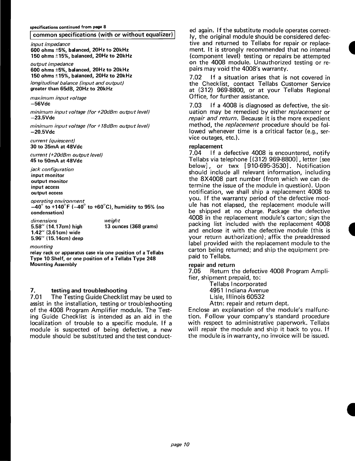
7. testing and troubleshooting
7.01 The Testing GuideChecklist may be
used
to
assist in the installation, testing
or
troubleshooting
of
the
4008
Program
Amplifier
module. The Test-
ing Guide Checklist
is
intended
as
an
aid in
the
localization
of
trouble
to
aspecific module. If a
module
is
suspected
of
being defective, anew
module should be substituted and
the
test conduct-
ed
again. If
the
substitute module operates correct-
ly,
the original module should
be
considered defec-
tive and returned
to
Tellabs
for
repair
or
replace-
ment.
It
is
strongly recommended
that
no internal
(component level) testing
or
repairs be attempted
on
the
4008
module. Unauthorized testing
or
re-
pairs may void
the
4008's warranty.
7.02 If a situation arises
that
is
not
covered in
the
Checklist, contact Tellabs Customer Service
at (312) 969-8800,
or
at
your
Tellabs Regional
Office,
for
further
assistance.
7.03
If
a
4008
is
diagnosed
as
defective, the sit-
uation may
be
remedied
by
either replacement
or
repair and return.
Because
it
is
the
more expedient
method,
the
replacement procedure should be fol-
lowed whenever
time
is
acritical
factor
(e.g.,
ser-
vice outages, etc.).
replacement
7.04
If a defective
4008
is
encountered,
notify
Tellabs via telephone [(312)
969-8800],
letter
[see
below],
or
twx
[910-695-3530].
Notification
should include all relevant
information,
including
the
8X4008
part number
(from
which we
can
de-
termine
the
issue
of
the
module in question). Upon
notification,
we shall ship areplacement 4008
to
you. If
the
warranty
period
of
the
defective mod-
ule
has
not
elapsed, the replacement module
will
be
shipped at no charge.
Package
the defective
4008
in
the
replacement module's carton;
sign
the
packing list included
with
the
replacement
4008
and enclose
it
with
the defective module (this
is
your
return
authorization);
affix
the
preaddressed
label provided
with
the replacement modu
Ie
to
the
carton being returned; and ship
the
equipment pre-
paid
to
Tellabs.
repair and return
7.05 Return
the
defective
4008
Program
Ampli-
fier,
sh
ipment
prepaid,
to:
Tellabs Incorporated
4951 Indiana Avenue
Lisle,
Illinois
60532
Attn:
repair and return dept.
Enclose
an
explanation
of
the
module's malfunc-
tion.
Follow
your
company's standard procedure
with
respect
to
administrative paperwork. Tellabs
will
repair the module and ship
it
back
to
you.
If
the
module
is
in warranty, no invoice
will
be
issued.

-
~
t
testing guide checklist
trouble condition possible
cause
(in order
of
likelihood)
no
gain 1)
Incorrect
setting
of
GAIN
RANGE
switch (see paragraph 3.12) D.
2) Power
input
polarity
D.
excessive high-frequency roll-off 1) Use
of
unbalanced
source
or
terminating
meter
with
simplex leads
or
sim-
plex
capacitors
grounded
D.
excessive low-frequency loss 1)
Improper
equalizer
adjustment
D.
2) Use
of
capacitively
coupled
meter
D.
inability
to
properly
equalize facility 1) Loss
in
excess
of
31dB
between
highest
frequency
of
interest
and
100Hz
D.
2) I
ncorrect
equalization
adjustment
(see
3.15
to
3.16,
or
figure 5)
D.
3) Non-uniform cable
frequency
response, including presence
of
load coils,
buildout
capacitors,
or
impedance
compensators
D.
4) Presence
of
cable bridge-tap, especially
at
point
of
connection
of
repeater D.
5)
Split
cable pairs
in
the
program
circuit
D.
audible pick
up
of
radio
station
1) Unbalanced cable pairs on
input
side
of
amplifier
D.
(Use
of
a
248RF
Assembly, 2)
Improper
power
supply grounding
D.
which
is
required
in
high 3) Enclosure covers
not
in place
D.
RF environments.
is
assumed.) 4)
Improper
grounding,
and
lead shielding
D.
excessive
60Hz
noise
when
mounted
1) Unbalanced cable pairs
D.
in
1912
Apparatus
Case 2)
Improper
ground
of
Apparatus
Case
and
dc
power
supply
(if used)
D.
3) I
mproper
connection
of
List 4
Transformer
(power
input
to
the
1912
should
be
connected
to
screws 1
and
3
on
the
List 4
Transformer)
D.
4) Low
power
voltage
(minimum
power
voltage
is
23Vdc
or-
26Vac
between
terminals
10
and
11
on
the
1912
barrier strip)
D.
excessive
60Hz
noise -
remote
1) Unbalanced cable pairs
D.
power
location 2) Failure
to
filter
power
feed
input
to
4008
(see paragraph 2.13)
D.
3)
Improper
arrangement
of
transformer
simplex
capacitor
grounds
and
transformer
shield
grounds
D.
4) Failure
to
locally
ground
jack sleeves (pin 55)
D.
Note:
Effects
of
cable unbalance can
be
determined
by
inserting aterminating
plug
into
the INPUT jack andmeasuring the noise
at
the
OUTPUT
jack. This
isolates the
amplifier
from the cable (in
both
directions,
if
appropriate), mak-
ingpossible the measurement
of
amplifier
noise
without
introduction
of
noise from the cable.
distortion
at
amplifier
output
1) Excessive
output
signal level
D.
2)
Input
signal level
too
high. especially
at
low frequencies
(input
signals
above
+10dBm
may overload first equalizer stage) (see
note,
page 5)
D.
Tellabs Incorporated
4951 Indiana Avenue, Lisle,
Illinois
60532
telephone (312)
969-8800
twx
910-695-3530
page
11
Table of contents
Other Tellabs Amplifier manuals


