2
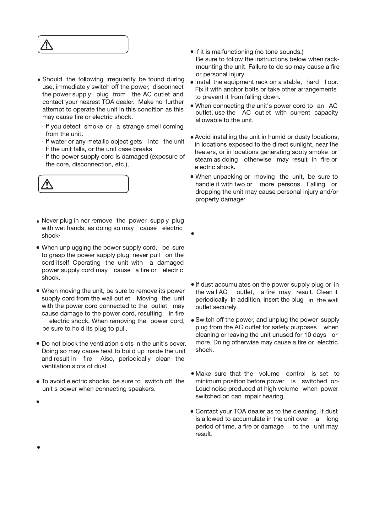
1. SAFETY PRECAUTIONS ...................................................................................................................
2. SYSTEM SUMMARY .........................................................................................................................
3. FEATURES ........................................................................................................................................
4. INSTALLATION PRECAUTIONS .........................................................................................................
5. NOMENCLATURE AND FUNCTIONS ...............................................................................................
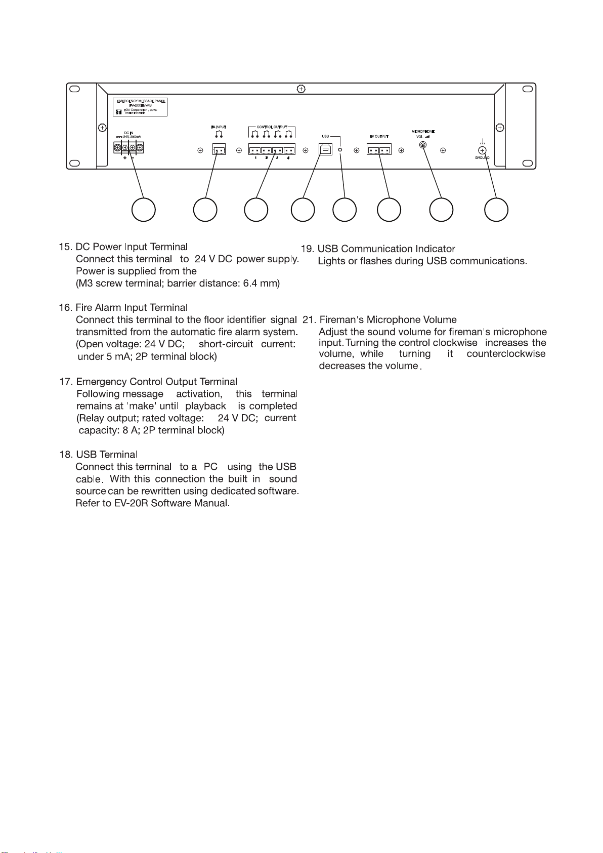
5.1. FV-200EV-AS Emergency Message Panel ................................................................................
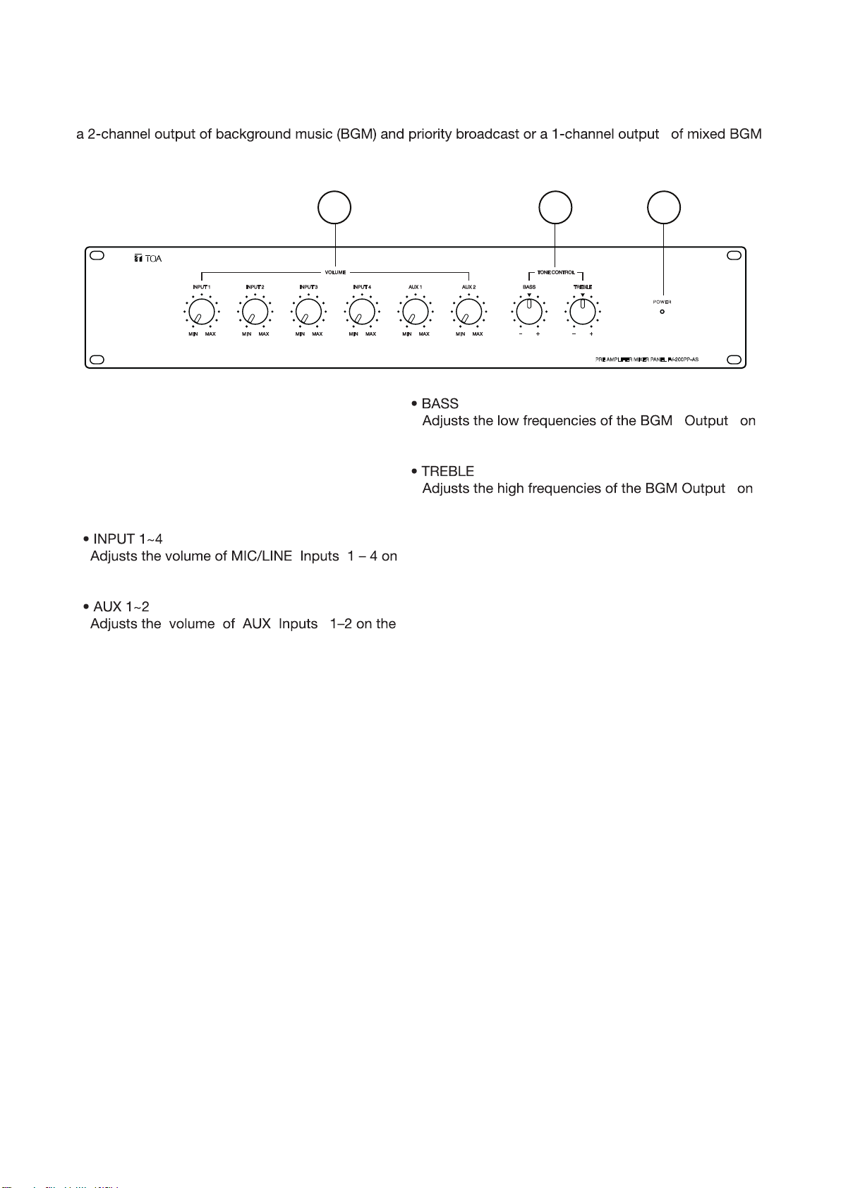
5.2. FV-200PP-AS Pre-Amplifier Mixer Panel ...................................................................................
5.3. FV-200RF-AS Microphone Receiver Panel ................................................................................
7. CONNECTIONS ..................................................................................................................................
7.1. Basic System Configuration .......................................................................................................
7.2. 24 V DC Power Supply Expansion ...............................................................................................
7.3. FV-200EV-AS Connection ..........................................................................................................
7.4. Timer-Operated Equipment ........................................................................................................
7.5. Telephone Paging .......................................................................................................................
7.6. RF-PP Link Connection ..............................................................................................................
7.7. RM-200M Connection .................................................................................................................
7.7.1. RM-200M Connection without AC adapter .....................................................................
7.7.2. RM-200M Connection with AC adapter ..........................................................................
7.8. BGM Instrument ..........................................................................................................................
7.9. Power Amplifier Connection ........................................................................................................
7.9.1. 1-Channel Broadcast .......................................................................................................
7.9.2. 2-Channel Broadcast ........................................................................................................
7.9.3. Power Amplifier Expansion ..............................................................................................
7.9.4. Power Amplifier Connection with SX-2000 system .........................................................
7.9.5. Power Amplifier Connection with VX-2000 system .........................................................
7.10. Connecting the Speaker and Attenuator ................................................................................
7.14. Speaker Selector Connection ..................................................................................................
7.14.1. 2-Channel Mode using SS-2010 ...................................................................................
7.14.2. 1-Channel Mode using SS-1010 ...................................................................................
7.14.3. 1-Channel Mode using SS-1010R .................................................................................
7.15. Automatic Fire Alarm Systems .................................................................................................
7.16. Fault Out Connection ...............................................................................................................
7.17. Power Failure Backup ..............................................................................................................
7.17.1. Providing Backup Power Using an Uninterruptible Power Supply (UPS) System ...........
7.17.2. Power Backup Using the VX-2000DS Emergency Power Supply Panel .........................
TABLE OF CONTENTS
4
6
7
7
8
8
10
13
28
29
30
31
31
32
33
34
35
36
36
37
37
37
38
39
39
40
43
43
43
44
44
45
45
45
45
5.4. FV-200CA-AS Amplifier Changeover Panel .................................................................................
14
5.5. FV-224PA-AS 240W Power Amplifier Panel ...............................................................................
5.6. FV-248PA-AS / FV-248PA-AS 4 F00 480W Power Amplifier Panel ...........................................
5.7. RM-200M Remote Microphone ...............................................................................................
5.8. RM-210 Remote Microphone Extension ...................................................................................
5.9. VP-200VX Power Amplifier Input Module .................................................................................
5.10.FV-200PS-AS DC Power Supply Panel
................................................................................
15
16
17
18
18
19
6. INSTALLATION .................................................................................................................................
6.1. Panels Installation ......................................................................................................................
6.1.1. Installing on the Cabinet Rack .........................................................................................
6.1.2. Cabinet Rack Installation .................................................................................................
6.1.3. Installation Example ........................................................................................................
6.2. Installing the RM-200M ...................................................................................................................
6.2.1. Installing RM-200M on the wall .......................................................................................
6.2.2. Installing RM-210 on the wall ..........................................................................................
6.2.3. Linking the RM-200M with the RM-210 (For Desktop Mounting) ....................................
6.2.4. Inserting the name label ....................................................................................................
6.2.5. Dimensional diagram for printing devices .........................................................................
6.2.6. Pattern paper for hand writing .........................................................................................
6.3. Installing the VP-200VX Power Amplifier Input Module in the Power Amplifiers .......................
6.4. Ground lifting using the VP-200VX Power Amplifier Input Module ............................................
20
20
20
20
21
22
22
23
24
25
25
26
27
28
7.11. Amplifier Changeover Connection ........................................................................................... 41
7.12. Amplifier Changeover Cascade Connection
............................................................................ 42
7.13. FV-200CA-AS Wrong Connection Warning ............................................................................ 42