tema AA-15IP Technical document

Revision
Date
Revision reason
Prepared
Checked/Approved
0 20/03/20 First release DP, FL DP, FL
MAS-AA15-REV00EN Page 1 of 32
AA-15IP
VoIP SIP / PoE interface for traditional Doorphones
TECHNICAL – INSTALLATION MANUAL
PRELIMINARY DOCUMENTATION
HW Version 1.0 - SW Version 1.10
Recommendations
1. Use only original spare parts and consumables supplied by Tema Telecomunicazioni Srl for this equipment. The company shall not be
held responsible for any damage caused by the use of materials that they have not supplied.
2. The device has been carefully manufactured and tested. In any case, the product is not recommended for use in situations in which
incorrect operating may result in damage to persons and/or property.
3. We recommend that you carefully read all this manual before starting to use the device.
4. Do not expose the device to sunlight and protect it from sources of heat, dust, humidity and chemical agents.
5. This manual is the property of Tema Telecomunicazioni Srl and any duplication and reproduction, even partial, as well as storage on
any type of media is forbidden without written permission from Tema Telecomunicazioni Srl.
TEMA TELECOMUNICAZIONI S.r.l.
Telecommunications - Electronics

TEMA TELECOMUNICAZIONI SRL
VoIP Doorphone Interface AA-15IP
MAS-AA15-REV00EN Page 2 of 32
We, TEMA TELECOMUNICAZIONI SRL Via C. Girardengo, 1/4 - 20161 MILANO
declare under our sole responsibility that the product:
product name
Modulo Intercom Audio e Video VoIP SIP / PoE
trade name TEMA TELECOMUNICAZIONI Srl
type or model AA-15
and accessories
to which this declaration relates is in conformity with the essential requirements and other
relevant requirements of the R&TTE Directive ( 1999/5/EC, 2006/95/EC, 2004/108/EC ).
The product is in conformity with the followings standards and/or other normative documents:
HEALT & SAFETY EN 60950-1:2006
+A11:2009
+A1:2010
+A12:2011
EMC EN 55022:2010
EN 55024:2010
EN 61000-3-2:2006
EN 61000-3-3 :2008
MILANO, 03 February 2020 TEMA TELECOMUNICAZIONI SRL
D. Pontillo
I.
IMPORTANT INFORMATIONS REGARDING THE RECOVERY AND RECYCLING OF THIS ELECTRONIC DEVICE
The crossed-out wheeled bin symbol below indicates that this electronic equipment is intended to be disposed in a separate collection and not in
an unsorted municipal waste, in order to provide for the treatment of WEEE (Waste Electrical and Electronic Equipment) using best available
recovery and recycling techniques. Specific treatment for WEEE is indispensable in order to avoid the dispersion of pollutants and other
hazardous substances into the waste stream, while recycling leads to reduction of disposal of waste and the negative impacts on environment
and human health. That is, priority is given to reuse of WEEE in its components, subassemblies and consumables. As the final holder, the user
has an important role in contributing to reuse, recycling and other forms of recovery of WEEE and is responsible to return this waste in th
e collection facilities set up by EC Member States and to fulfill other duties in compliance with Directive 2002/96/EC and local laws.
DICHIARAZIONE DI CONFORMITÀ CE
DECLARATION OF CONFORMITY CE
UNI
EN ISO 9001:20
15
TEMA TELECOMUNICAZIONI
is a certified company

TEMA TELECOMUNICAZIONI SRL
VoIP Doorphone Interface AA-15IP
MAS-AA15-REV00EN Page 3 of 32
RECOMMENDATIONS
1. It is recommended to read this entire manual before proceeding to the installation of the device.
2. The installation and commissioning of the device can only be performed by specialized technicians.
3. The device is accurately manufactured and tested. In any case, the product is not recommended for use
where an error of operations can cause property damage and/or injury to persons.
4. It is expressly not recommended maintenance inside the device which must be carried out by Tema
Telecomunicazioni, the removal of the closures will invalidate the warranty and makes accessible internal
parts with risk of electric shock.
5. Tema Telecomunicazioni accepts no responsibility for damage to property and/or persons resulting from
incorrect use of the equipment or by procedures that do not comply with the instructions in this manual.
Tema Telecomunicazioni reserves the right to make modification to the technical and functional
specifications at any time and without any notice.
6. Products powered via PoE (Power over Ethernet) may only be connected with cables coming from the
internal network company (inside the building), are not allowed connections LAN cables coming from outside
the building.
7. Use for this device only and exclusively original spare parts and consumables supplied by Tema
Telecomunicazioni. The company is not responsible for damage caused by the use of materials not supplied
by the same.
8. Do not expose the unit to direct sunlight, protect from heat, dust, humidity and chemicals.
9. Tema Telecomunicazioni reserves the right to vary the product characteristics for improvement without prior
notice. Check the WWW.TEMATLC.IT website for any updates to the latest firmware, manuals, and
technical documentation.
10. This document is property of Tema Telecomunicazioni, It is forbidden any duplication and reproduction, even
partial, as well as storage on any medium without written permission of Tema Telecomunicazioni.
This symbol in the descriptions indicates a general warning or a damage danger
to equipment or people.
This symbol in the descriptions indicates useful information or a suggestion for
the optimization of the device functionality.
This symbol in the descriptions indica
tes an electric shock hazard for damage to the equipment or
people.

TEMA TELECOMUNICAZIONI SRL
VoIP Doorphone Interface AA-15IP
MAS-AA15-REV00EN Page 4 of 32
1. PRESENTATION ........................................................................................................................................ 5
2. TYPICAL OPERATING DIAGRAM........................................................................................................... 6
3. PACKING LIST ........................................................................................................................................... 6
4. GENERAL FEATURES.............................................................................................................................. 7
5. TECHNICAL FEATURES........................................................................................................................... 7
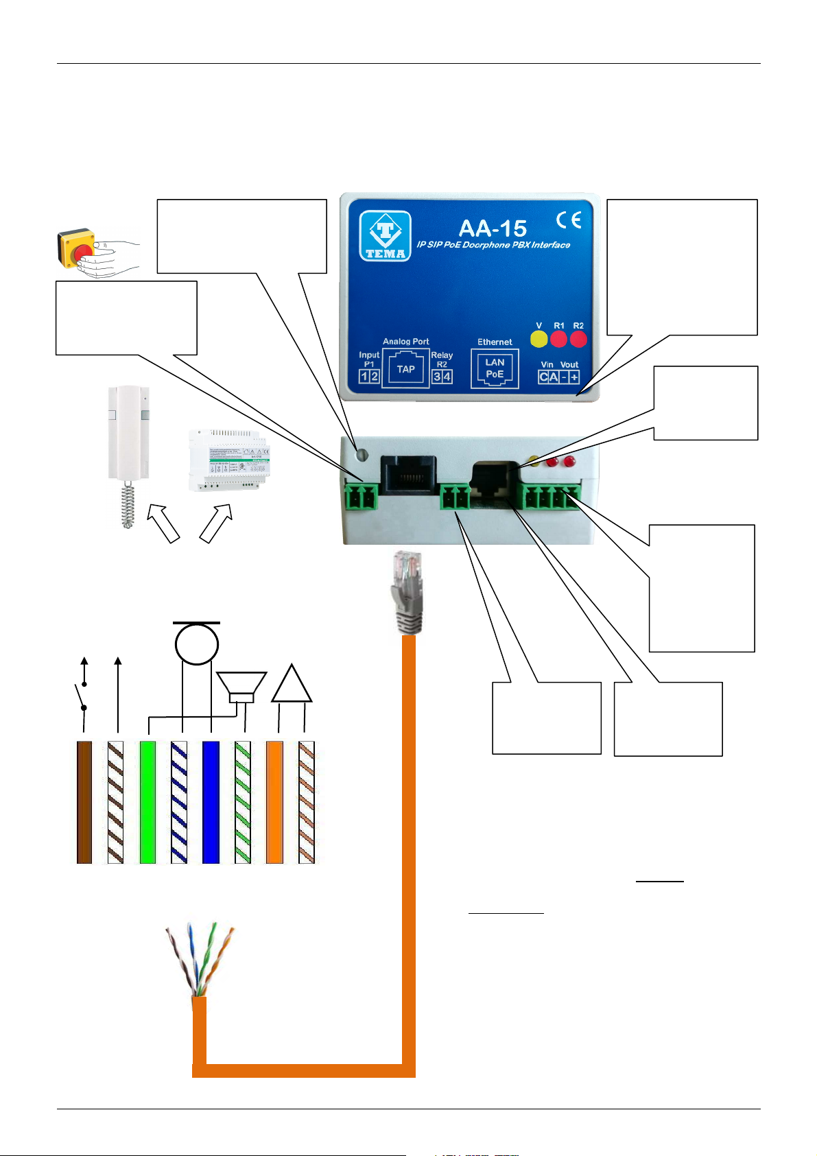
6. INSTALLATION .......................................................................................................................................... 8
6.1.
CONNECTION ................................................................................................................................................8
7. PROGRAMMING ...................................................................................................................................... 11
7.1.
P
REPARATION FOR THE SYSTEM PARAMETERS PROGRAMMING
..............................................................................11
7.2.
A
CCESS TO PROGRAMMING
...............................................................................................................................13
7.3.
N
ETWORK PARAMETERS
...................................................................................................................................14
7.4.
SIP
P
ARAMETERS
...........................................................................................................................................15
7.5.
P
ARAMETRI GENERALI
......................................................................................................................................16
7.6.
S
ET OF THE OPERATING MODE
D
AY
/N
IGHT
/I
NTERVAL
,
K
EYBOARD
.........................................................................17
7.7.
D
AY
/N
IGHT
/I
NTERVAL DESCRIPTION
...................................................................................................................18
7.8.
D
AY
/N
IGHT
/I
NTERVAL COMMAND CODES FOR THE OPERATOR
...............................................................................18
7.9.
R
ELAY AND ALARM SETTINGS
............................................................................................................................19
7.10.
A
CQUISITION OF INPUT ALARM CONTACTS
......................................................................................................20
7.11.
C
ALL BUTTONS
...........................................................................................................................................21
7.12.
M
ESSAGES MANAGEMENT
...........................................................................................................................21
8. MAINTENANCE........................................................................................................................................ 22
8.1.
S
YSTEM
..........................................................................................................................................................22
8.2.
L
OGIN CREDENTIALS
........................................................................................................................................23
8.3.
D
IAGNOSTIC LOG
.............................................................................................................................................23
9. APPENDIXES............................................................................................................................................ 24
9.1.
U
SE OF THE
AUDACITY
SOFTWARE FOR AUDIO FILES RECORDING
.......................................................................24
9.2.
C
ABLING OF A
UTP
RJ45
NETWORK CABLE ACCORDING TO THE STANDARD
EIA568B.............................................25
9.3.
C
ONNECTION WITH
URMET
INTERCOM
..............................................................................................................26
9.4.
C
ONNECTION WITH
URMET
MOD
.
1130
INTERCOM
.............................................................................................27
9.5.
C
ONNECTION WITH
BPT
INTERCOM
...................................................................................................................28
9.6.
C
ONNECTION WITH
TERRANEO
INTERCOM
.......................................................................................................29
9.7.
C
ONNECTION WITH
FARFISA
INTERCOM
...........................................................................................................30
9.8.
C
ONNECTION WITH
COMELIT
INTERCOM
...........................................................................................................30
9.9.
FAQ
F
REQUENTLY
A
SKED
Q
UESTIONS
..............................................................................................................31
INDEX PAGE

TEMA TELECOMUNICAZIONI SRL
VoIP Doorphone Interface AA-15IP
MAS-AA15-REV00EN Page 5 of 32
1. PRESENTATION
The AA-15IP device allows to interface any traditional doorphone (4 or 5 wires) to an IP-PBX in order to manage
the doorphone from any internal extension or, in the absence of an IP-PBX, it can also work with a common SIP
phone in P2P (Peer-to-Peer) mode. When a visitor presses the call button of the existing doorphone, AA-15
generate a SIP call to a programmed extension number by putting the visitor in communication with the operator
who answered, who has the possibility to operate, with a code from the phone, the relay for opening the entrance
gate. A second relay can be activated, from the internal telephone as well, for other services.
When an IP-PBX is present, the calls from the intercom can be routed to an external telephone number, including
mobile numbers.
The device has an external contact input that can be used as an alarm dialer: when closed, AA-15IP calls a
programmed number and alerts the event with a customizable voice message.
If there is no IP-PBX, the basic functions (communication and gate opening relay activation) are obtained by
connecting a normal IP-SIP phone and programming AA-15IP in P2P (Peer-to-Peer) mode.
It is possible to connect AA-15IP both to the central unit of the doorphone system or directly to the internal
station (wall-mounted intercom) of the single user.
AA-15IP integrates a PoE power supply and can therefore be powered on the same cat5/6 LAN cable if coming
from a PoE switch. Alternatively, an input for external 230Vac power supply is available (Optional).
The dimensions 76.5x62xH32.5mm (connectors excluded) they are extremely compact and the system can be
fixed to the wall with the included bracket or on a DIN bar with a special accessory (Optional).
Main features
♦
Can be connected with all 4-5 wires doorphones models, DIN rail mounting
♦
1 power open-door relay and 1 auxiliary relay
♦
Up to 2 configurable extension numbers (in case of no answer)
♦
3 alternative programmable numbers according to day/night/interval times (need internet access)
♦
Relay: configurable opening and closing contact
♦
Activity display LED
♦
Easy programming via Web browser
♦
Compatible with the most popular IP-PBX brands
Total Management via LAN, integrated Web Server
Programming, configuration, loading and listening of audio files, firmware update, audio volume adjustment,
backup, configuration reset, device reboot.
Integration in telephone VoIP SIP and security systems
AA-15IP integrates perfectly with VoIP telephony systems (IP-PBX) with SIP protocol that can be registered as a
normal VoIP phone or in Peer-to-Peer (P2P) mode without a PBX.
Tested with the most popular P X brands:
SIEMENS/UNIFY - AVAYA - ALCATEL – PANASONIC – SAMSUNG - NEC - 3CX
LG ERICSSON - WILDIX - AASTRA - ASCOM - NITSUKO – SELTA - PHILIPS
MITEL – YEASTAR - ZYCOO – CISCO – EPYGI ELASTIX – GRANDSTREAM –
SHORETEL - NORTEL – SWYX – XORCOM – ASTERISK-BASED SYSTEMS
SOFTPHONE OF DIFFERENT MANUFACTURERS

TEMA TELECOMUNICAZIONI SRL
VoIP Doorphone Interface AA-15IP
MAS-AA15-REV00EN Page 6 of 32
2. TYPICAL OPERATING DIAGRAM
When the visitor presses the button, AA-15IP generates a SIP call to an internal number, putting the visitor in
communication with the operator, who has the possibility to operate the gate opening relay with a code from the
phone. In any case, the internal doorphone station remains operational since AA-15IP works in parallel.
The contacts of Relay 2 can also be brought to the internal station to allow the opening of a second gate or to
switch on any lights.
Both relays can be activated not only following the call from the doorphone but also by calling AA-15IP to the
assigned number/IP address, wait for the answer and activate them with codes from the telephone keypad.
In the presence of the IP-PBX, calls from the doorphone can be routed to external phone numbers, including
mobile.
IMPORTANT NOTE: the quality of the audio received and transmitted is strictly dependent on the quality of
the intercom system, the device does NOT correct any disturbances or low audio quality of the existing
intercom system but transfers the audio exactly as it receives it.
3. PACKING LIST
The system consists of the parts included in the following list:
•1 AA-15 interface module
•1 CD with system documentation
•1 quick guide
•1 ABS bracket for wall mounting + 2 screws
•1 RJ45 1.5mt LAN cable
•1 RJ45 cable for TAP socket
NOTE: an optional kit is available for fixing the AA-15 module on a DIN bar, code AA-697/DIN.
RELAY 1
Visitor
PoE Switch
8 signal wires
from internal
station
IP SIP Phone
AA
-
15IP
PSTN
UTP
Cable
cat 5/6
UTP
Cable
cat 5/6
Alarm
input
Doorphone
central unit
IP
-
PBX
SIP
SERVER
Operator and internal
network telephones
RELAY 2
auxiliary
Existing
external
Doorphone
Existing
internal station

TEMA TELECOMUNICAZIONI SRL
VoIP Doorphone Interface AA-15IP
MAS-AA15-REV00EN Page 7 of 32
4. GENERAL FEATURES
•
Sending a telephone call upon detection of an intercom call
•
Programming via Web interface with password protection
•
Day/Night/Interval manual or automatic mode for different call destination numbers
•
2 door opener relays for the possibility of activating a second electric lock
•
Setting of the Day/Night/Interval operating mode can be performed by telephone or automatically with time
slots, the settings will be retained even in the event of a power failure (requires Internet Time Server access)
•
Great versatility coupled with ease of use and programming
•
Possibility of software / firmware update via LAN
•
Possibility of acquiring 1 external contact to the system and warning service with dedicated message
•
Manual "Door opener" function from internal button, to be associated with the available input contact
VoIP IP LAN section
•
Integration with the local LAN, LAN 100 BaseT Ethernet port with RJ45 connector
•
VoIP connection with SIP protocol both in SIP Proxy Server mode (Registration on IP-PBX) and Peer-to-
Peer, possibility of PoE (Power over Ethernet) power supply
5. TECHNICAL FEATURES
Generals
Insertion terminals for wiring
Possibility of
using cables up to 1.5mm2 or AWG16
Number of integrated relays
2
Max relay contact capacity
Up to
2A
-
30V
Main unit power supply
12VDC / VAC, 900mA max of absorption
Container material
ABS Novodur®
Mounting type
Wall or DIN rail mounting (optional a
ccessory)
Operating temperature
From
-
20
˚C
to
+50
˚C
Relative humidity
95%
non
condensino
VoIP
Power supply via PoE
According to
IEEE 802.3af
(only for system power supply, not for electric locks)
LAN
LAN 100 BaseT
Ethernet
Port
Supported
VoIP
protocols
SIP v2
Supported modes
SIP Serv
er
or
Peer
-
to
-
Peer
modes
Protocols
IP, TCP, UDP, HTTP
, TELNET, SIP, RTP
Bandwidth
300
–
3400 Hz
(7KHz
with
G722
codec)
A
udio
c
odec
G711µ, G711a, G722
Ec
h
o
s
uppressor
Yes
Inputs
Number of acquisition inputs
1 for alarm/call

TEMA TELECOMUNICAZIONI SRL
VoIP Doorphone Interface AA-15IP
MAS-AA15-REV00EN Page 8 of 32
6. INSTALLATION
6.1. CONNECTION
The connection of the device must only be carried out by qualified technical personnel.
Signaling LED
YELLOW: active
communication
REDs:
relay 1 and 2
activation
RX volume adjustment
Alarm contact input
C
-
A
Power input
12V-0,5A
indifferent
polarity
Auxiliary
voltage
output
RJ45 PoE
LAN
Cable
Auxiliary
relay 2
output
UTP cable from TAP
8 7 6 5 4 3 2 1
BR WH GR WH BL WH OR WH
BR BL GR OR
~
MIC
SP
LOCK
OPENING
BUZZER
TO THE DOORPHONE
(Indoor station or central power supply)
TAP
The terminations of the UTP cable coming
from the RJ45 socket called "TAP" must be
connected to the terminals of the internal
station or to the respective signals of the
central power supply in parallel with the
existing cables, since AA-15 works in a totally
transparent way and therefore allows normal
operation of the intercom.

TEMA TELECOMUNICAZIONI SRL
VoIP Doorphone Interface AA-15IP
MAS-AA15-REV00EN Page 9 of 32
Removable screw terminal blocks
1-2 Input P1
Terminal for detecting the alarm contact (1 = contact, 2 = GND)
3-4 Relay R2
Auxiliary relay, range 30V-1Amp, normally open contact
C, A
Terminal for powering the system, irrelevant polarity
+ Vout
Terminal from which it is possible to draw power, POSITIVE
- GND
Terminal from which it is possible to draw power, NEGATIVE
LAN RJ45 port
The module requires a cable for connection to the LAN. If the cable also carries PoE power supply, it will not be
necessary to supply the module with other power sources. PoE power supply can coexist with any power supply
from an external power supply.
TAP Analog Port RJ45
All the signals connected to the traditional intercom are brought to this input to be processed by the internal
electronics and converted into VoIP-SIP protocols.
IMPORTANT NOTE: the quality of the audio received and transmitted is strictly dependent on the quality of the
intercom system, the device does NOT correct any disturbances or low audio quality of the existing intercom system
but transfers the audio exactly as it receives it.
Devices powered via PoE (Power over Ethernet) may only be connected with cables coming from
inside the building, they are not allowed connections to LAN cables coming from outside the
building.
To the t
erminals 1 and 2 must only be connected to a relay or button contact that is f
ree of any
voltage to avoid permanent damage to the device.
At the "+Vout" output there is a + 12Vdc voltage when the device is powered via PoE, otherwise, at
this output the voltage will be the same as at the terminals A-C. The use of "+Vout" is permitted as
long as it is not exceeded a maximum 200mA current consumption and the load has a protection on
the input current. Improper use of this output will permanently damage the unit.

TEMA TELECOMUNICAZIONI SRL
VoIP Doorphone Interface AA-15IP
MAS-AA15-REV00EN Page 10 of 32
B 1 2 3 5
6
4-7
In
ternal unit terminals
B> Free
1SP > 6 Green
2MIC > 4 Blue
3-4-5 COM > 1-3-5-7
6RING > 2 Orange
7LOCK > 8 Brown
Example of connection with
“ELVOX” intercoms
5 wires BUS
AA
-
15 is connected with a UTP cable from the RJ45 "TAP" socket on the terminals of the indoor station (in parallel with the
wires
already connected to the intercom system). The signals for the AA-15IP interface are taken from the group of 6 terminals. Terminal
4-7 carries the first relay inside AA-15 which activates the lock following a code dialed on the internal telephone keypad. The device
works transparently while maintaining the functionality of the indoor station which can continue to be used normally. A second relay
is available for other functions. An alarm input is available which, if closed, makes a phone call and sends a message.
NOTE: see the wiring diagrams of other brands and models of interphones in the appendices at the bottom of the manual.
8 7 6 5 4 3 2 1
UTP cable from TAP PoE Switch
IP PBX
SIP SERVER
IP
-
SIP
Phone
Alarm
contact
input
Second
auxiliary
relay
12Vdc/Vac
Input
(if PoE not
available)
12Vdc
Max
200mA
Output
Tip
:
before proceeding to
unscrew the terminal screws,
it is preferable to mark the
colors of the existing cables
attested on the terminals on a
piece of paper.
DOORPHONE
MAINS
POWER SUPPLY

TEMA TELECOMUNICAZIONI SRL
VoIP Doorphone Interface AA-15IP
MAS-AA15-REV00EN Page 11 of 32
7. PROGRAMMING
7.1. Preparation for the system parameters programming
Programming is done via the WEB interface. To gain access, simply connect an Ethernet cable from a PC or from a
switch to the LAN port of AA-15IP.
The default IP address of AA-15IP is "192.168.0.10".
Remember that in order to successfully connect to the web interface of AD635, it is necessary that, in the IP
addresses configuration of your PC, is present the subnet 192.168.0.x, where "x" is any number between 1 and
254 and different from 10. See below how to configure your PC to reach the correct subnet. The shown procedure
applies to Windows® operating systems.
Open the Windows Control Panel and set the field "View by": "Category" "Large Icons" or "Small Icons".
Choose "Network and Sharing Center" as shown in the first figure, detect your LAN connection, choosing the one
referring to the network card that you are using to connect with AA-15IP.

TEMA TELECOMUNICAZIONI SRL
VoIP Doorphone Interface AA-15IP
MAS-AA15-REV00EN Page 12 of 32
Once the correct connection is identified, click on it and it will appear the window where it is necessary to click on
the "Properties" button. It will then open the window where must be selected "Internet Protocol Version 4
(TCP/IPv4)" and then click the Properties button again. See the following figures:
If the PC is already on subnet 192.168.0.x with a mask 255.255.255.0, ignore the following steps. Otherwise,
proceed as follows. (The address of the PC configuration should not be 192.168.0.10). Remember the current
TCP/IP configuration of your computer for any subsequent restore of the correct parameters. Click "Use the
following IP address" and type in the appropriate field the following IP address: 192.168.0.11 (instead of "11" used
in the example it is possible to enter any number between 1 and 254, but excluding the 10 which is the default
address of the system to be programmed). In the "Subnet Mask" enter the netmask 255.255.255.0. Click OK to
confirm the changes. The PC is now ready to configure the door phone. Remember at the end of programming to
restore the network configuration of the PC to its original state if necessary.
Once the IP address of your PC is successfully configured, it is possible to reach the Web interface to configure
AA-15IP at the address 192.168.0.10 .

TEMA TELECOMUNICAZIONI SRL
VoIP Doorphone Interface AA-15IP
MAS-AA15-REV00EN Page 13 of 32
7.2. Access to programming
To program the device, it is sufficient to use a standard browser such as Explorer, Firefox, Chrome or others. The
default address of the device is 192.168.0.10 with a mask of 255.255.255.0, and the user/password with which to
connect are master/master. Make sure to have access to this network segment from your computer. Once logged
in, it is possbile to change the administrative password for the maximum safety of your device. Once logged in, it is
possbile to change the administrative password for the maximum safety of your device, see par.8.2
The use is very simple and intuitive, the menu for selecting the functions to be programmed is always visible on the
left, while the configuration mask active at that time is shown on the right. Each change will be confirmed with the
"Apply" or "Save" buttons. Closing the browser or changing pages without selecting these buttons will make any
changes lost.
Any changes do not require restarting the device (except changing the IP address and updating the software).

TEMA TELECOMUNICAZIONI SRL
VoIP Doorphone Interface AA-15IP
MAS-AA15-REV00EN Page 14 of 32
7.3. Network parameters
On this page it is possible to set the network parameters, such as IP address, netmask, etc.:
The default IP address of the device is 192.168.0.10/24. Gateway and DNS are only needed if you want the device
to have the ability to access the Internet (for example to get the current date/time, in the example from the site
time.nist.gov).
The changes to the network settings are taken over by the device until the next reboot. Once you have completed
the configuration steps so be sure to reboot the system and if necessary, change the network segment of your
computer so that it can connect to the new address.
•IP address: specify the IP address you want to assign to AA-15.
•Subnet mask: indicate the subnet mask to be assigned to AA-15.
•Default gateway: indicate the gateway that can enable AA-15 to access to internet.
•Primary and secondary DNS server: indicate the addresses of two DNS servers you want to use to resolve
IP addresses.
•Time server: indicate the address of the server you want to use for time synchronization device.
•Test address (ping): if inserted, this address is used by the system to verify the correct operation of the
network connection.
•Device description: text that will appear on the search mask of the supervision Tema Adam software (for
this device it is not necessary).

TEMA TELECOMUNICAZIONI SRL
VoIP Doorphone Interface AA-15IP
MAS-AA15-REV00EN Page 15 of 32
7.4. SIP Parameters
Once the network parameters have been set correctly, you must configure the connection with the VoIP SIP PBX:
•SIP server address: specify the IP address of the SIP PBX to which AA-15 should connect.
•Port: is the port number of the SIP PBX with which AA-15 must operate. Generally it is the 5060, but some
stations use a different port.
•Domain: enter the domain to which register the system.
•Outbound proxy: some PBXs require that the extension number to call is followed by the proxy address. In
most cases this field can be left empty.
•Local SIP port: generally the 5060 port is used, but it is possible to specify a different number (i.e. for
particular routing tables).
•User/password: credentials for the registration of the extension (which obviously must have been already
created on the PBX).
•Expiration: indicates how many seconds the device should check the correct registration of the client.

TEMA TELECOMUNICAZIONI SRL
VoIP Doorphone Interface AA-15IP
MAS-AA15-REV00EN Page 16 of 32
7.5. Parametri generali
In this section it is possible to set parameters for general use, such as call duration, audio volume, and so on:
•Connection time: once in connection with the extension, the call is torn down anyway after the set time.
Thirty seconds before the end of the call, the system will emit a short beep to the user within the company
and repeats the message every 5 seconds. At this stage it is possible to type on the extension phone the
sequence "#5", which forces the connection time to be reloaded.
•Answer time for incoming calls: when the system is called, it answers after the set time. If set to 0,
responds immediately, if 999 never answers. In any case, when there is an incoming call, it is possible to
answer by pressing any key.
•Connection ad communication code: when the device receives an incoming call, if this field is programmed,
the audio will not be connected until the user will enter the right connection code.
•Monitoring code: as in the previous case, for incoming calls, the audio is not connected until the code is
entered, but in this case only the audio from microphone is connected (a sort of “monitor” function, it is
possible to hear the audio near the doorphone).
•Calling speaker volume: sets the volume of the audio to the external user. Possible values range from 0
(very low) to 9 (very strong).
•Microphone volume: Sets the microphone sensitivity and consequently the volume of the audio to the user
within the company. Possible values range from 0 (very low) to 9 (very strong).
•Local Ringer volume: sets the volume of the ringer issued by the system for incoming calls. Possible values
range from 0 (mute ringer) to 9 (very strong).
•Tone signalling/Tone volume: has NO effect in this version (Future expansion of services).
•Echo Limiter Threshold: this parameter indicates the audio level above which to exchange speech between
the caller and the called party. Leave the default value.

TEMA TELECOMUNICAZIONI SRL
VoIP Doorphone Interface AA-15IP
MAS-AA15-REV00EN Page 17 of 32
7.6. Set of the operating mode Day/Night/Interval, Keyboard
In the operating mode, it is possible to set the mode to DAY/NIGHT/INTERVAL, either manually or automatically
following time slots per week. This page is also configured to change the codes to the remote phone and
coordinates the installation (they are used to manage the twilight mode of relay 2, see par. 7.9):
•Current mode: allows to set the current mode of operation.
•Change mode codes: enter the codes to change mode remotely (from any internal phone, call the Speaker
and, at the answer, via DTMF type the code corresponding to the selected mode). The codes must consist
of 2 characters.
•Time bands: in the case of automatic operation, it is possible to enter up to 5 bands per day. If a field is left
blank, it is unused and the previous corresponding band will be used.
•Time zone: time zone of the location where the installation is made (+1 for Italy)
•Latitude/Longitude: Geographical decimal coordinates relative to the installation site. Can be retrieved
easily from the internet (eg. www.mapcoordinates.net/en).
The time zone and geographic coordinates are necessary if you wish to use and consequently activate relay 2 in
"twilight" mode (see 7.9) to signal an external lighting system to activate when evening falls and deactivate in the
morning according to pre-established times and dependent on the geographical position.

TEMA TELECOMUNICAZIONI SRL
VoIP Doorphone Interface AA-15IP
MAS-AA15-REV00EN Page 18 of 32
7.7. Day/Night/Interval description
In each of the three possible modes of operation, at the press of a button the system makes a call to a number (or
two numbers if the second number is also programmed) for a parmeterizabile number of times. It is also possible to
specify an additional final number, called "supervisor", to be contacted at the end of the previous attempts. The call
is considered to be successful when the operator answers.
The visitor listens to the signals of the call in progress preceded by a possible courtesy voice message, when
enabled.
If the visitor presses a button again while the call is in progress the system interrupts the call and returns to sleep.
In systems with keyboard expansion to interrupt the call in progress, press the asterisk (*) key.
The system can be placed in Day, Night or Interval mode manually (the operator will send a special command to
the system) or it can automatically switch to each mode based on a time schedule.
When the visitor presses the button, a call is made to one of the PBX extensions associated with the pressed
button. The numbers that will be called may differ depending on the operating mode in which the system is located,
Day-Night-Interval mode (see par. 7.6).
In the case of expansion with a keyboard, this allows the desired number to be dialed directly or to manage
additional functions described below.
If the keypad is used in Quick Select mode, described below, the descriptions of the operating modes below are
valid only for the numbers associated with the Speed Dial.
7.8. Day/Night/Interval command codes for the operator
The commands described here to set the operating mode to default will have these codes. Normally it is possible to
reach AA-15 from any extension of the PBX to give DTMF commands, simply by dialing the number of the internal
extension to which AA-15 is connected.
DTMF
Command
Function Description
*1 Set the Day mode
Puts AA-15 in Day mode.
*2 Set the Night mode
Puts AA-15 in Night mode.
*3 Set the Interval mode
Puts AA-15 in Interval mode.
*0 Set the Automic mode
AA-15 will select the operating mode based on a table
of preset time slots.

TEMA TELECOMUNICAZIONI SRL
VoIP Doorphone Interface AA-15IP
MAS-AA15-REV00EN Page 19 of 32
7.9. Relay and alarm settings
On this page it is possible to choose the operating mode of the two internal device relays and the operating mode
for external inputs:
•Mode: sets the function to be associated to the relay. It is possible to choose between:
1 Electric lock: is activated only upon receiving the activation code.
2 In call: is activated when a call is in progress and until the door phone does not come back to idle
3 In call + timer: it activated when a call is in progress and for the activation time
4 Pressure button: you press any key relay is activated for the time set
Only for the relay 2
5 After relay 1: When you operate the relay 1, relay 2 is activated also for the time set
6 Twilight: In this mode the relay is activated 30 minutes before sunset and 30 minutes after sunrise.
The calculation of sunrise and sunset is done automatically by the system based on the current
time and location of the installation (the exact time should be obtained from the internet).
•PHONE activation: relay activation code to dial from the extension of the PBX (2 characters required)
•Activation time: activation time of the relay
•Activation delay: for relay 2, after how many seconds you have to turn with respect to the activation of relay
1 (if set in "after Relay 1")
•Close call: by setting this option, your call is immediately hang up when the relay is activated
Commands described here by default will have these codes:
DTMF
Command
Function Description
#1 Activate the door
opener contact of relay 1
Used to activate the electric lock connected to the first
relay during communication, it is a 2-digit code, by
default #1.
#2 Activate the door
opener contact of relay 2
Used to activate the second relay during
communication, it is a 2-digit code, by default #2.
#5 Conversation time extension
Continuing the conversation with the visitor, at the
notice of AA-15 regarding the expiration of the same, it
is possible to reload the original time to continue the
conversation. AA-15 warns with some tones 30
seconds before closing.

TEMA TELECOMUNICAZIONI SRL
VoIP Doorphone Interface AA-15IP
MAS-AA15-REV00EN Page 20 of 32
Normally it is possible to reach AA-15 from any extension of the PBX to issue DTMF commands, simply by dialing
the number of the internal extension to which AA-15 is connected.
7.10. Acquisition of input alarm contacts
The following screenshot shows the configuration parameters of the alarm event following the closure of an
external contact.
•Call..: number or IP address of the phone to contact when the alarm condition is triggered. The input could
be also used as “door opener”: enter the number of the relay preceded by #. For exampe #1 activate the
relay 1, #2 activate the relay 2. The activation time is the one entered in the activation time filed.
•Attempts: number of call attempts (max 999)
•Separation: separation, in seconds, between a call attempt and the other (max 999).
•Delay: it is the minimum time, in seconds, before validating the input. It could be useful, for example, to
mask an open door switch. Supposing the maximum time of a pedestrian gate is 30 seconds, at the end of
this time (if the switch would be still active) an alarm will be send to the reception.
•Inversion: the contact is normally open and the alarm occurs at the closing of the same. Enabling this flag it
is possible to instruct the device to behave in the opposite way (the contact is normally closed and the
alarm occurs at the opening).
•Stop code: code to dial on the phone calling to accept and acknowledge the alarm (max 3 digits).
•Announce: when activating this input, a prerecorded message will be played on the speaker. See
messages management.
The input is associated with a message to be reproduced during the call. A neutral message (“Alarm1”) is
reproduced as standard but the text can be customized. It is possible to associate a phone number or an IP
address that will be called during the alarm phase.
The closure of an external contact triggers the signaling sequence but it is also possible to reverse this logic, so the
signaling can occur following the opening of the contact connected to the input. AA-15 continuously monitors the
contact status and if the activation condition occurs, will call the person at the programmed telephone number and
reproduces the message associated with the relative input.
It is possible to define an alarm acquisition / acknowledgment code that the called party must key in to inform AA-
15 of the alarm taking charge. If the called number is busy or does not answer or in any other case in which AA-15
does not receive the acquisition code, the system returns to rest.
The number of times the alarms are notified and the time between one notification attempt and the next are
programmable, while the time for which the warning message is reproduced is the "Attempts" time set in the
general parameters. At the end of the notification attempts, the alarm condition signal ceases, no further notification
calls will be made.
To be able to be triggered again the notification phase of an activation, the condition that had triggered the previous
notification must return to rest. Only after the occurrence of a new contact activation condition will the notification
cycle with notification calls restart.
However, if the contact that triggered the signal has remained closed, another warning cycle will NOT be triggered!
To get again notices related to this contact it is necessary that it returns first to rest (re-opening) and then on its
new closure AA-15 will be activated again.
Table of contents
Popular Recording Equipment manuals by other brands

Opvimus
Opvimus IF-722ETH operating instructions

Studio Technologies
Studio Technologies StudioComm 780-01 user guide

Bosch
Bosch DX4010V2 installation instructions

Sima
Sima Speaker Selectors SSW-L4EX Features

Cochlear
Cochlear SPrint Sound Processor troubleshooting manual

Felston
Felston HD940 owner's manual