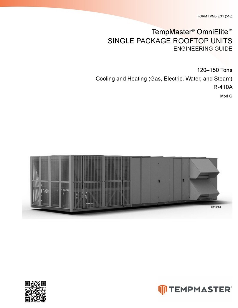
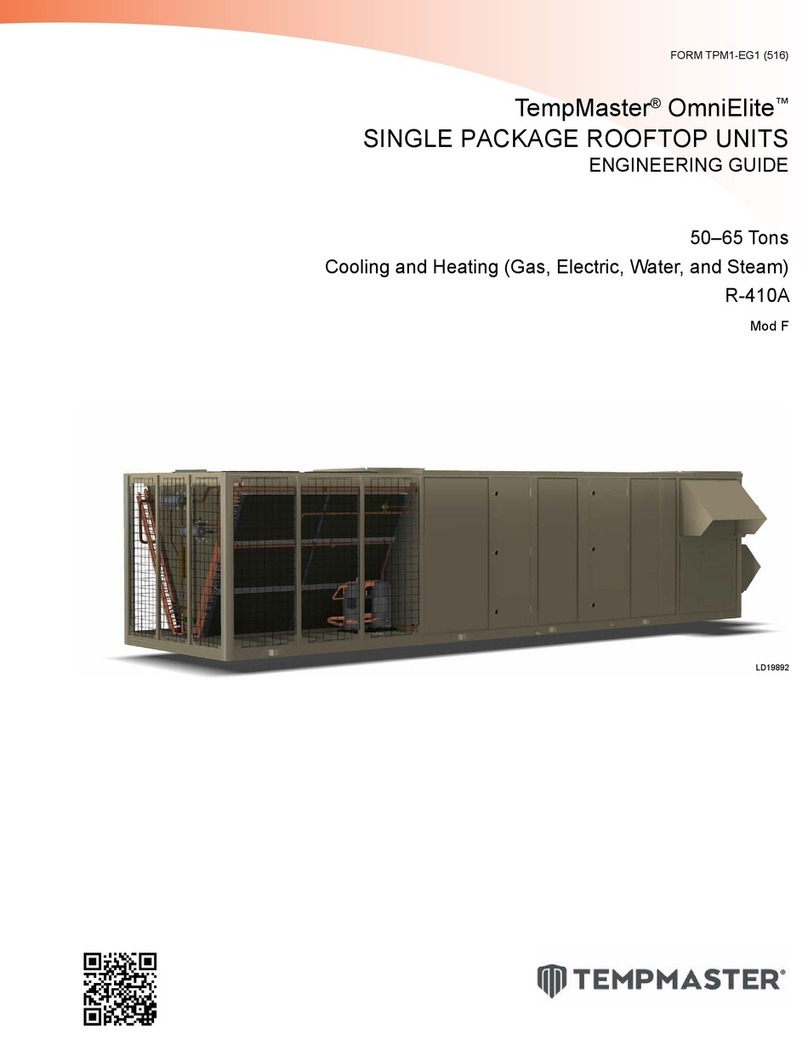
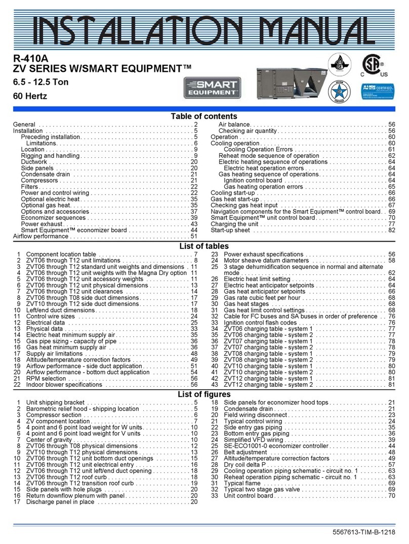
TempMaster Omni Premier 25 Ton Product manual

Form Number: 5881373-TIM-421
New Release
Installation Guide
Issue Date: 2021-04-01
Tempmaster
Tempmaster® Omni™ Premier 25 Ton
to 80 Ton Rooftop Units Installation and
Maintenance Guide

2Tempmaster® Omni™ Premier 25 Ton to 80 Ton Rooftop Units Installation and Maintenance Guide
Tempmaster

Contents
ContentsChangeability of this document.................................. 5
Associated literature............................................... 5
Nomenclature 25 ton to 80 ton model number........ 6
General........................................................................... 9
Introduction........................................................... 15
Ecological and economical design...................... 15
Condensing section.............................................. 15
Scroll compressors.......................................... 15
Multiple compressor staging......................... 15
Compressor circuiting.................................... 16
Compressor sound blankets.......................... 16
Replaceable core filter driers......................... 16
Low ambient operation.................................. 16
Condenser fan motors................................... 16
Condenser coils............................................... 16
Condenser coil protection.............................. 16
Blank section......................................................... 16
Sound attenuator............................................ 16
Humidifier........................................................ 16
Air blender....................................................... 16
Evaporator section................................................ 16
Evaporator coils............................................... 16
Modulating hot gas reheat............................ 16
Double sloped stainless steel drain pan....... 17
Heating section..................................................... 17
Gas heat........................................................... 17
Electric heat..................................................... 17
Hydronic heat.................................................. 17
Air management................................................... 17
Fans................................................................... 17
Premium efficiency motors............................ 17
Building pressure control............................... 17
Variable frequency drives............................... 17
Fan spring isolation........................................ 18
Energy recovery wheel................................... 18
Controls.................................................................. 18
Rooftop unit controller................................... 18
BACnet®/Modbus™/N2/Customer
terminal board.................................................. 18
Indoor air quality.................................................. 18
Indoor air quality............................................ 18
Double wall construction............................... 18
Demand control ventilation........................... 18
Smoke control.................................................. 19
Filtration........................................................... 19
Ultraviolet lights.............................................. 19
Electrical................................................................. 19
Single point power.......................................... 19
Dual point power............................................. 19
Power phase monitor..................................... 19
Unit-mounted disconnect, 65 kA SCCR......... 19
Service and Installation........................................ 19
Split ship........................................................... 19
Internal lights.................................................. 19
Access doors, padlocks, viewports,
safety latch and door tiebacks........................ 19
Service valves and sight glasses.................... 20
Convenience outlet......................................... 20
Condenser safety tie-off................................. 20
Condenser cleaning hatch............................. 20
Burglar bars..................................................... 20
Inlet, belt guard and spare belts................... 20
Start-up and air balancing wizard................. 20
Factory run-tested........................................... 20
RTUToolKit app and QR code......................... 20
Safety considerations........................................... 22
Limitations............................................................. 23
Reference............................................................... 23
Approvals............................................................... 23
Installation................................................................... 24
Unit inspection...................................................... 24
Long term storage.......................................... 24
Unit placement...................................................... 24
Roof curb................................................................ 24
Clearances and locations............................... 24
Rigging and handling........................................... 26
Weights and unit dimensions.............................. 30
Weights............................................................. 30
Dimensions...................................................... 33
Roof curb dimensions..................................... 47
Submittal data....................................................... 61
Electrical data........................................................ 61
Electrical service sizing................................... 62
Control wiring........................................................ 69
Occupancy input............................................. 69
Safety switch input.......................................... 69
Tempmaster
Tempmaster® Omni™ Premier 25 Ton to 80 Ton Rooftop Units Installation and Maintenance Guide 3

Main control board.................................................. 69
Customer terminal board....................................... 69
Options board.......................................................... 70
Display panel.................................................................. 72
Display panel adjustment....................................... 72
Reset switch.................................................................... 74
Unit enable switch......................................................... 74
UV light reset switch...................................................... 75
Field tubing..................................................................... 75
Discharge air static pressure transducer.............. 75
Building static pressure transducer....................... 75
Outdoor pressure reference................................... 75
Outside air temperature sensor............................. 76
Gas piping....................................................................... 76
Gas connection......................................................... 77
Gas piping recommendation.................................. 77
Flue gas chimney installation................................. 78
Hydronic piping.............................................................. 78
Hot water coil........................................................... 78
Steam coil.................................................................. 80
Humidifier....................................................................... 80
Ductwork......................................................................... 81
Discharge panel....................................................... 82
Air hoods......................................................................... 83
Outside air hood...................................................... 83
Exhaust air hood...................................................... 84
Filters............................................................................... 84
Ultraviolet lights............................................................. 85
Condensate drain........................................................... 85
Fan tie-downs................................................................. 86
Start-up and operation.................................................. 91
Maintenance......................................................................... 92
General............................................................................ 92
Safety......................................................................... 92
Condenser safety tie-off.......................................... 92
Periodic maintenance - monthly........................................ 93
Belt tensioning............................................................... 93
Filters............................................................................... 93
Linkages.......................................................................... 93
Compressors................................................................... 93
Oil level check........................................................... 93
Oil analysis................................................................ 93
Condenser and evaporator coils.................................. 93
Hot water and steam coils............................................ 94
Periodic maintenance - 3 months to 6 months................ 95
Motor bearing lubrication............................................. 95
Lubrication preparation.......................................... 95
Lubrication procedure............................................. 95
Fan bearing lubrication................................................. 97
Condensate drain........................................................... 98
Periodic maintenance - yearly............................................ 99
Entire unit inspection.................................................... 99
Condensate float switch................................................ 99
Ultraviolet lights............................................................. 99
Internal lights................................................................. 99
Sheave alignment.......................................................... 99
Belts............................................................................... 100
Belt replacement.......................................................... 100
Filter drier replacement.............................................. 100
Energy recovery wheel................................................ 101
Remove the wheel holder supports..................... 101
Sliding the ERW...................................................... 102
Remove wheel segments...................................... 103
Install wheel segments......................................... 104
Periodic maintenance - as needed.................................. 105
Replacing the main control board............................. 105
Phase monitor checks and adjustments................... 105
Compressor replacement........................................... 105
Technical supplement....................................................... 106
25 ton to 50 ton power wiring side penetration for
slab-mounted units...................................................... 106
Installing the power wiring through the side
panel of the rooftop unit........................................ 106
60 ton to 80 ton power wiring side penetration for
slab-mounted units...................................................... 107
Installing the power wiring through the side
panel of the rooftop unit........................................ 107
Technical supplement....................................................... 108
Installing door tie-back brackets (5881370-UTS-
A-0420)............................................................................ 108
Supplément technique...................................................... 109
Instructions d'installation du chauffage au gaz...... 109
Chauffage à gaz..................................................... 109
Les dégagements................................................... 110
Tuyauterie de gaz................................................... 111
Connexion de gaz.................................................. 112
Recommandation sur la tuyauterie de gaz......... 113
Installation de cheminée de gaz de
combustion.............................................................. 113
Tempmaster® Omni™ Premier 25 Ton to 80 Ton Rooftop Units Installation and Maintenance Guide
4
Tempmaster

Changeability of this
document
In complying with the manufacturer's policy
for continuous product improvement, the
information contained in this document is
subject to change without notice. There is no
commitment to update or provide current
information automatically to the manual or
product owner. Updated manuals, if applicable,
can be obtained by contacting the nearest
service office.
It is the responsibility of rigging, lifting,
and operating/service personnel to verify
the applicability of these documents to the
equipment. If there is any question regarding
the applicability of these documents, rigging,
lifting, and operating/service personnel
should verify whether the equipment has been
modified and if current literature is available
from the owner of the equipment prior to
performing any work on the equipment.
Associated literature
Manual Description Form Number
Omni™ Premier 25 Ton to 80 Ton Rooftop Units Installation and
Maintenance Guide 5881373-TIM
Omni™ Premier 25 Ton to 80 Ton Rooftop Units R-410A Start-Up and
Operation Guide 5881376-TSG-A
Omni™ Premier 60 Ton to 80 Ton Rooftop Units Split Ship Assembly
Installation Manual 6011418-TIM
Omni™ Premier 25 Ton to 80 Ton Rooftop Units Advanced Graphic
Touchscreen Display 5795594-TIM-A
Mobile Access Portal Gateway (MAP) Technical Guide 1154578-UTG-A
Note: Unit-specific documents such as unit drawings, curb information, performance
summary, weights, center of gravity, electrical data, rigging and shipping instructions,
sequence of operation, BAS controls points, and hydronic valve specifications are available
in the Selection Navigator program. Contact your local sales office or representative for
additional unit-specific information.
WARNING
Cancer and Reproductive Harm — www.P65Warnings.ca.gov.
5
Tempmaster® Omni™ Premier 25 Ton to 80 Ton Rooftop Units Installation and Maintenance Guide
Tempmaster

Nomenclature 25 ton to 80 ton model number
Digits 1–2: Product brand name
GT: Tempmaster
Digit 3: Capacity
A: 25 ton
B: 30 ton
C: 40 ton
D: 50 ton
F: 60 ton
H: 70 ton
J: 80 ton
Digit 4: Efficiency
1: Standard capacity, standard efficiency, staged control
2: Standard capacity, high efficiency, modulating control
3: High capacity, standard efficiency, staged control*
4: Standard capacity, standard efficiency, low sound, staged
control*
5: Standard capacity, high efficiency, low sound, modulating
control*
6: High capacity, standard efficiency, low sound, staged
control*
Digit 5: Heat source
A: Cooling only
B: Staged gas aluminized burner
C: Staged gas stainless steel (SST)
G: Modulating gas stainless steel
K: Steam coil*
L: Hot water coil*
M: Electric heat*
Digit 6A: Electric heat capacity
0: None
1: Low heat*
3: High heat*
4: Low heat with silicon controlled rectifier (SCR)*
6: High heat with SCR*
Digit 6B: Natural gas heat capacity
0: None
1: 250 MBH
2: 500 MBH
3: 750 MBH
4: 1,000 MBH
5: 1,250 MBH
6: 1,500 MBH
Digit 6C: Hot water or steam heating coil option
0: None
1: Low heat without valves*
2: Low heat with valves*
3: High heat without valves*
4: High heat with valves*
Digit 7: Unit type
A: Single zone VAV (SZVAV) (no duct pressure transducer)
B: Variable air volume (VAV) (duct pressure transducer)
Digit 8: Motor control options
1: Supply fan variable frequency drive (VFD)
2: Supply fan VFD with line reactor*
3: Supply fan VFD with bypass (redundant VFD) / Supply fan
with dual VFD
4: Supply fan VFD with line reactor and bypass (redundant
VFD) / Supply fan with dual VFD with line reactor*
5: Supply fan VFD and return/exhaust fan VFD
6: Supply fan VFD with line reactor and return/exhaust fan
VFD with line reactor*
7: Supply fan VFD and return/exhaust fan VFD with bypass
(redundant VFD for supply fan and bypass for return or
exhaust fan) / Supply fan with dual VFD and redundant VFD
for return fan / manual bypass for exhaust fan
8: Supply fan VFD with line reactor and return/exhaust
fan VFD with line reactor with bypass (redundant VFD for
supply fan and bypass for return or exhaust fan / Supply
fan with dual VFD and redundant VFD for return fan /
manual bypass for exhaust fan, and line reactors (for all
fans)*
Digit 9: Voltage
A: 208-230 V 3Ph 60 Hz, single point terminal block
B: 208-230 V 3Ph 60 Hz, dual point terminal block
C: 208-230 V 3Ph 60 Hz, single point non-fused DISC
D: 208-230 V 3Ph 60 Hz, single point terminal block, 65KA
short-circuit current rating (SCCR)*
E: 208-230 V 3Ph 60 Hz, dual point terminal block, 65KA
SCCR*
F: 208-230 V 3Ph 60 Hz, single point fused DISC, 65KA SCCR*
G: 460 V 3Ph 60 Hz, single point terminal block
H: 460 V 3Ph 60 Hz, dual point terminal block
J: 460 V 3Ph 60 Hz, single point non-fused DISC
K: 460 V 3Ph 60 Hz, single point terminal block, 65KA SCCR*
L: 460 V 3Ph 60 Hz, dual point terminal block, 65KA SCCR*
M: 460 V 3Ph 60 Hz, single point fused DISC, 65KA SCCR*
N: 575 V 3Ph 60 Hz, single point terminal block
P: 575 V 3Ph 60 Hz, dual point terminal block
Q: 575 V 3Ph 60 Hz, single point non-fused DISC
R: 575 V 3Ph 60 Hz, single point terminal block, 65KA SCCR*
S: 575 V 3Ph 60 Hz, dual point terminal block, 65KA SCCR*
T: 575 V 3Ph 60 Hz, single point fused DISC, 65KA SCCR*
Digit 10: Return configuration
A: Bottom return, right outside air (OA), side exhaust
B: Bottom return, right OA, front exhaust
C: Bottom return, left OA, side exhaust
D: Bottom return, Left OA, front exhaust
E: Top return, right OA, side exhaust (no return fan
available)*
F: Top return, right OA, front exhaust (no return fan
available)*
G: Top return, left OA, side exhaust (no return fan
available)*
H: Top return, left OA, front exhaust (no return fan
available)*
J: Left return, right OA, front exhaust
K: Right return, left OA, front exhaust*
L: Front return, left OA, right exhaust*
M: Front return, right OA, feft exhaust*
N: Bottom return, no OA, no exhaust air (EA) (no return fan
available)
P: Top return, no OA, no EA (no return fan available)*
Q: Left return, no OA, no EA (no return fan available)
R: Right return, no OA, no EA (no return fan available)*
S: Front return, no OA, no EA (no return fan available)*
Digit 11: Discharge locations
1: Bottom discharge, from discharge plenum
2: Bottom discharge, discharge through heat section
3: Top discharge, from discharge plenum*
4: Right discharge, from discharge plenum
5: Left discharge, from discharge plenum
6: Left discharge, discharge through heat section
Digit 12: Supply configuration
A: None
B: Small blank
C, D: Large blank*
E, G: Large blank with final filter*
F: Small blank with humidifier and SST drain pan*
H, K: Large blank with humidifier and SST drain pan*
L: Small blank sound attenuator*
M, N: Large blank sound attenuator*
P: Small blank final filter
Q, T: Large blank with sound attenuator and final filter*
S, V: Large blank with sound attenuator and humidifier and
SST drain pan*
Digit 13: Final filter options
1: MERV 15 bag final filters with 2 in. MERV 8 filters
2: MERV 14 rigid final filters with 2 in. MERV 8 filters
3: MERV 17 high efficiency particulate air (HEPA) final filters
with 2 in. MERV 8 filters*
4: MERV 14/15 filter rack (no filters)
5: HEPA filter rack (no filters)*
6: None
Digit 14: Final filter control options
0: None
1: Combined pre- and post- filter transducer
2: Separate pre- and post- filter transducer
3: Combined pre- and post- filter transducer and combined
magnehelic gauge
Tempmaster® Omni™ Premier 25 Ton to 80 Ton Rooftop Units Installation and Maintenance Guide
6
Tempmaster

4: Separate pre- and post- filter transducer and magnehelic
gauge
5: Combined pre- and post- filter magnehelic gauge
6: Separate pre- and post- filter magnehelic gauge
7: Combined pre- and post- filter transducer, separate pre-
and post- filter magnehelic gauge
Digit 15: Supply fan
A: Direct drive plenum (DDP) supply fan with 1 in. spring
isolation
B: DDP supply fan with 2 in. spring isolation
C: DDP supply fan with 2 in. spring isolation and seismic
restraint
D: Dual direct drive plenum supply fans with 1 in. spring
isolation
E: Dual direct drive plenum supply fans with 2 in. spring
isolation
F: Dual direct drive plenum supply fans with 2 in. spring
isolation and seismic restraint
Digit 16: Supply fan motor horsepower
A: 5 HP / 5 HP x 2
B: 7.5 HP / 7.5 HP x 2
C: 10 HP / 10 HP x 2
D: 15 HP / 15 HP x 2
E: 20 HP / 20 HP x 2
F: 25 HP / 25 HP x 2
G: 30 HP / 30HP x 2
H: 40 HP
J: 50 HP
Digit 17: Supply fan motor type
2: ODP premium efficiency 1,800 RPM
4: TEFC premium efficiency 1,800 RPM
Digit 18: Supply fan options
0: None
1: Inlet guard
2: Airflow measurement station
3: Shaft grounding ring
4: Inlet guard and airflow measurement station
5: Inlet guard and shaft grounding ring
6: Airflow measurement station and shaft grounding ring
7: Shaft Grounding Ring, Inlet Guard and Airflow
Measurement Station
Digits 19: Building pressure control
0: None
1: Barometric damper
2: Exhaust with VFD and backdraft damper
3: Modulating damper (on/off exhaust fan only without
VFD)
4: Modulating damper (return fan only with VFD)
Digit 20: Return/exhaust fan
A: None
B: Exhaust fan with 1 in. spring isolation
C: Exhaust fan with 2 in. spring isolation
D: Exhaust fan with 2 in. spring isolation and seismic
restraint
E: Return fan with 1 in. spring isolation
F: Return fan with 2 in. spring isolation
G: Return fan with 2 in. spring isolation and seismic
restraint
H: DDP return fan with 1 in. spring isolation
J: DDP return fan with 2 in. spring isolation
K: DDP return fan, fan with 2 in. spring isolation and seismic
restraint
Digit 21: Return/exhaust fan motor horsepower
A: None
E: 3 HP
F: 5 HP
G: 7.5 HP
H: 10 HP
J: 15 HP
K: 20 HP
L: 25 HP
M: 30 HP
N: 40 HP
Digit 22: Return/exhaust fan motor type
0: None
1: ODP premium efficiency 1,200 RPM
2: ODP premium efficiency 1,800 RPM
3: TEFC premium efficiency 1,200 RPM*
4: TEFC premium efficiency 1,800 RPM*
Digit 23: Return/exhaust fan options
A: None
B: Shaft grounding ring
C: Extended grease lines
D: Extended grease lines and shaft grounding ring
E: Belt guards*
F: Belt guards and shaft grounding ring*
G: Return fan airflow measurement station
H: Return fan airflow measurement station and shaft
grounding ring
J: Extended grease lines and belt guards*
K: Extended grease lines and belt guards and shaft
grounding ring*
L: Extended grease lines and return fan airflow
measurement station
M: Extended grease lines and return fan airflow
measurement station and shaft grounding
N: Belt guards and return fan airflow measurement station
P: Belt guards and return fan airflow measurement station
and shaft grounding ring
Q: Extended grease lines and belt guards and return fan
airflow measurement station
R: Extended grease lines and belt guards and return fan
airflow measurement station and shaft grounding ring
R: Extended Grease Lines and Belt Guards and Return Fan
Airflow Measurement Station and Shaft Grounding Ring
Digits 24: Return/exhaust fan drive
A: None (25-50 ton)
0: None (60-80 ton)
1-9: RPM
A-Z: RPM
Digit 25: Evaporator options
G: Aluminum fin evaporator with SST drain pan
H: Aluminum fin evaporator with SST drain pan with
condensate overflow switch
J: E-Coat aluminum fin evaporator with SST drain pan*
K: E-Coat aluminum fin evaporator with SST drain pan with
condensate overflow switch*
L: Copper fin evaporator with sst drain pan*
M: Copper fin evaporator with SST drain pan with
condensate overflow switch*
Digit 26: Condenser coil options
2: With wire guards
3: Full louvered panels*
4: Partial louvered panels with wire guards*
6: E-Coat condenser with wire guards*
7: E-Coat condenser, full louvered panels*
8: E-Coat condenser, partial louvered panels with wire
guards*
Digit 27: Draw-through filter options
A: Angled filter rack, no filters
B: Angled filter rack, 2 in. throwaway filters
C: Angled filter rack, 2 in. MERV 8 filters
D: Rigid filter rack, no filters
E: Rigid filter rack, MERV 15 bag filters with 2 in. MERV 8
pre-filters
F: Rigid filter rack, MERV 14 rigid filters with 2 in. MERV 8
pre-filters
G: Vertical filter rack, no filters
H: Vertical filter rack, 4 in. MERV 8 filters
Digit 28: Draw-through filter control options
0: None
1: Combined pre- and post- filter transducer
2: Separate pre- and post- filter transducer
3: Combined pre- and post- filter transducer and combined
magnehelic gauge
4: Separate pre- and post- filter transducer and magnehelic
gauge
5: Combined pre- and post- filter magnehelic gauge
6: Separate pre- and post- filter magnehelic gauge
7: Combined pre- and post- filter transducer, separate pre-
and post- filter magnehelic gauge
Digit 29: Economizer options
A: None
C: Dry bulb economizer, low leak dampers
D: Single enthalpy economizer, low leak dampers
E: Dual enthalpy economizer, low leak dampers
F: Dry bulb economizer, low leak dampers with airflow
measurement station
G: Single enthalpy economizer, low leak dampers with
airflow measurement station
H: Dual enthalpy economizer, low leak dampers with
airflow measurement station
K: Dry bulb economizer, ultra low leak dampers
L: Single enthalpy economizer, ultra low leak dampers
S: Dual enthalpy economizer, ultra low leak dampers
T: Dry bulb economizer, ultra low leak dampers with airflow
measurement station
U: Single enthalpy economizer, ultra low leak dampers with
airflow measurement station
V: Dual enthalpy economizer, ultra low leak dampers with
airflow measurement station
Digit 30: Energy recovery options
0: None
1: Low cubic feet per minute (CFM) energy recovery wheel
(ERW) without VFD*
2: Low CFM ERW with VFD*
3: High CFM ERW without VFD*
4: High CFM ERW with VFD*
Tempmaster® Omni™ Premier 25 Ton to 80 Ton Rooftop Units Installation and Maintenance Guide 7
Tempmaster

Digit 31: Refrigeration system piping options
A: None
B: Suction and discharge valves
C: Suction, discharge, and liquid valves
D: Suction, discharge, and liquid valves with replaceable
core filter driers*
E: Hot gas reheat (HGRH)
F: Suction and discharge valves with HGRH
G: Suction, discharge, and liquid valves with HGRH
H: Suction, discharge, and liquid valves with replaceable
core filter driers with HGRH*
N: E-Coat HGRH*
P: Suction and discharge valves with E-Coat HGRH*
Q: Suction, discharge, and liquid valves with E-Coat HGRH*
R: Suction, discharge, and liquid valves with replaceable
core filter driers with E-Coat HGRH*
Digit 32: Lights/detectors/ convenience options
A: None
B: Convenience outlet
C: Convenience outlet and internal lights*
D: Supply smoke detector
E: Return smoke detector
F: Supply and return smoke detector
G: Convenience outlet with supply smoke detector
H: Convenience outlet with return smoke detector
J: Convenience outlet with supply and return smoke
detectors
K: Convenience outlet and internal lights with supply smoke
detector*
L: Convenience outlet and internal lights with return smoke
detector*
M: Convenience outlet and internal lights with supply and
return smoke detectors*
Digit 33: Controls options
A: None
B: Low ambient
D: Subcool and superheat measurement
E: Low ambient with subcool and superheat measurement
Digit 34: Interface options
A: BACnet® MS/TP, Modbus™, N2
B: BACnet IP
G: BACnet MS/TP, Modbus, N2 with mobile access portal
(MAP)
H: MAP with BACnet IP
K: BACnet MS/TP, Modbus, N2 with MAP and touchscreen*
L: Touchscreen with MAP with BACnet IP*
N: BACnet MS/TP, Modbus, N2 with customer terminal
board
P: BACnet IP with customer terminal board
U: BACnet MS/TP, Modbus, N2 with MAP and customer
terminal board
V: MAP with BACnet IP and customer terminal board
X: BACnet MS/TP, Modbus, N2 with touchscreen and MAP
and customer terminal board*
Y: Touchscreen with MAP with BACnet IP and customer
terminal board*
Digit 35: Indoor air quality (IAQ) options
0: None
1: Ultraviolet (UV) lights*
2: Carbon Dioxide (CO2) sensors, demand controlled
ventilation
3: UV lights, CO2 sensors, demand controlled ventilation*
Digit 36: Gas heat shipped loose kits
0: None
1: Gas heat, side penetration
2: Gas heat, bottom penetration
3: Gas heat, high altitude kit natural gas (NG), side
penetration*
4: Gas heat, high altitude kit NG, bottom penetration*
5: Gas heat, high altitude kit liquid propane (LP), side
penetration*
6: Gas heat, high altitude kit LP, bottom penetration*
7: Gas heat, LP conversion kit, side penetration*
8: Gas heat, LP conversion kit, bottom penetration*
Digit 37: Security options
0: None
1: Supply and return opening burglar bars
2: Supply opening burglar bars
3: Return opening burglar bars
Digit 38: Door options
0: None
1: Viewport*
2: Single handle with padlock*
3: Single handle with padlock and viewport*
Digit 39: Cabinet shipping options
1: Single piece construction
2: Two piece construction
Digit 40: Curb options
A: No roof curb
B: Full perimeter roof curb
C: Pedestal curb
Digit 41: Pre-evap options
0: None
1, 2: Blank pre-evap extension, no air blender*
3, 4: Blank pre-evap extension, with air blender*
1, 2: Blank Pre-Evap Extension, No Air Blender
3, 4: Blank Pre-Evap Extension, with Air Blender
Digit 42: Shipped loose options
0: None
1: Spare Belts for Return/Exhaust
Digit 43: Construction standard
0: None
Digit 44: Supply fan VFD frequency
1: 68 Hz
2: 70 Hz
3: 72 Hz
A: 66 Hz
B: 64 Hz
C: 62 Hz
D: 60 Hz
E: 58 Hz
F: 56 Hz
G: 54 Hz
H: 52 Hz
J: 50 Hz
K: 48 Hz
L: 46 Hz
M: 44 Hz
N: 42 Hz
P: 40 Hz
Q: 38 Hz
R: 36 Hz
S: 34 Hz
T: 32 Hz
U: 30 Hz
V: 28 Hz
W: 26 Hz
X: 24 Hz
Y: 22 Hz
Z: 20 Hz
Digit 45: Supply fan brake horsepower (each motor)
A: 2 HP
B: 3 HP
C: 5 HP
D: 7.5 HP
E: 10 HP
F: 15 HP
G: 20 HP
H: 25 HP
J: 30 HP
K: 40 HP
L: 50 HP
M: 60 HP
N: 75 HP
Digit 46: Return fan brake horsepower
B-L : Internal use only
Digit 47: Future 4
0: None
Digit 48: Testing and special quotation (SQ)
0, Y, Z: None
T: Record test report
M: Mechanical special
1: Mechanical special and record test report
S: Software special
3: Software special and record test report
B: Mechanical and software special
5: Mechanical and software special and record test report
Digit 49: Generation/revision level
1: First generation
2: Second generation
Note:
*Item noted will be available in the future for the 60 ton to 80 ton cabinet.
Tempmaster® Omni™ Premier 25 Ton to 80 Ton Rooftop Units Installation and Maintenance Guide
8
Tempmaster

General
Table 1: Physical data
Unit size 25 ton 30 ton 40 ton 50 ton 60 ton 70 ton 80 ton
Compressor data - standard capacity, standard efficiency
Quantity/size
(nominal HP) 1/4.5, 1/7, 1/10 1/5.5, 1/7,
1/7, 1/7.5
1/5.5, 1/8.5,
1/10, 1/11.5
1/7.5, 1/10,
1/11.5, 1/15
1/12, 1/12,
1/15, 1/15
1/10, 1/15,
1/15, 1/20
1/15, 1/15,
1/15, 1/20
Type Scroll Scroll Scroll Scroll Scroll Scroll Scroll
Capacity steps 7 11 15 15 8 9 7
Number of circuits 2 2 2 2 2 2 2
Compressor data - high capacity, standard efficiency
Quantity/size
(nominal HP) 1/5, 1/7.5, 1/10 1/5.5, 1/7,
1/7, 1/ 8.5
1/7, 1/13,
1/8.5, 1/10
1/8.5, 1/15,
1/7.5, 1/15
Type Scroll Scroll Scroll Scroll
Capacity steps 7 11 15 11
Number of circuits 2 2 2 2
Compressor data - standard capacity, high efficiency
Quantity/size
(nominal HP) 1/5, 1/7.5, 1/13 1/7, 1/7, 1/18.5 1/7.5, 1/7.5,
1/10, 1/13
1/10, 1/10,
1/12, 1/17.5
1/10, 1/15,
1/15, 1/17.5
1/13, 1/15,
1/15, 1/27
1/15, 1/15,
1/15, 1/27
Type Scroll Scroll Scroll Scroll Scroll Scroll Scroll
Capacity steps 15–100% 15–100% 15–100% 15–100% 15–100% 15–100% 15–100%
Number of circuits 2 2 2 2 2 2 2
Supply fan
Quantity of fans/
motors 1/1 1/1 1/1 1/1 2/2 2/2 2/2
Type Direct drive
plenum
Direct drive
plenum
Direct drive
plenum
Direct drive
plenum
Direct driven
plenum
Direct driven
plenum
Direct driven
plenum
Size (in.) 27 27 33 33 27 27 27
Motor size range each
fan (min to max HP) 5–25 5–25 10–50 10–50 5-30 5-30 5-30
Airflow range (min to
max CFM) 5,000–12,000 5,000–12,000 8,000–20,000 8,000–20,000 12,000-24,000 14,000-32,000 14,000-32,000
Total static pressure
range (min to max iwg) 1.0–8.0 1.0–8.0 1.0–8.0 1.0–8.0 1-8.3 1-8.3 1-8.3
Return fan
Quantity of fans/
motors 1/1 1/1 1/1 1/1 1/1 1/1 1/1
Type Belt-driven
plenum
Belt-driven
plenum
Belt-driven
plenum
Belt-driven
plenum
Direct driven
plenum
Direct driven
plenum
Direct driven
plenum
Size (in.) 27 27 30 30 33 33 33
Motor size range (min
to max HP) 5–10 5–10 5–20 5–20 7.5-40 7.5-40 7.5-40
Airflow range (min to
max CFM) 5,000–12,000 5,000–12,000 8,000–20,000 8,000–20,000 12,000-24,000 14,000-32,000 14,000-32,000
Total static pressure
range (min to max iwg) 0.5–3.0 0.5–3.0 0.5–3.0 0.5–3.0 0.5–3.0 0.5–3.0 0.5–3.0
Exhaust fan
Quantity of fans/
motors 1/1 1/1 1/1 1/1 1/1 1/1 1/1
Type Belt-driven
forward curved
Belt-driven
forward curved
Belt-driven
forward curved
Belt-driven
forward curved
Belt-driven
forward curved
Belt-driven
forward curved
Belt-driven
forward curved
Size (in.) 18–18 18–18 25–25 25–25 30-30 30-30 30-30
Motor size range (min
to max HP) 3–15 3–15 5–20 5–20 5-25 5-40 5-40
Tempmaster® Omni™ Premier 25 Ton to 80 Ton Rooftop Units Installation and Maintenance Guide 9
Tempmaster

Table 1: Physical data
Unit size 25 ton 30 ton 40 ton 50 ton 60 ton 70 ton 80 ton
Airflow range (min to
max CFM) 5,000–12,000 5,000–12,000 8,000–20,000 8,000–20,000 12,000-24,000 14,000-32,000 14,000-32,000
Total static pressure
range (min to max iwg) 0.5–3.0 0.5–3.0 0.5–3.0 0.5–3.0 0.5–3.0 0.5–3.0 0.5–3.0
Condenser fan
Quantity 2 2 4 4 4 6 6
Type Propeller Propeller Propeller Propeller Propeller Propeller Propeller
Size (diameter in in.) 30 30 30 30 30 30 30
Power (HP) 2 2 2 2 2 2 2
Evaporator coil - standard capacity, standard efficiency
Size (sq. ft.) 24 24 36 36 49.5 66 66
Number of rows/fins
per in. 3/17 5/17 4/17 4/17 5/17 5/17 6/17
Size (tube diameter in
in.) 3/8 3/8 3/8 3/8 3/8 3/8 3/8
Evaporator coil - high capacity, standard efficiency
Size (sq. ft.) 24 24 36 36
Number of rows/fins
per in. 4/17 6/17 4/17 6/17
Size (tube diameter in
in.) 3/8 3/8 3/8 3/8
Evaporator coil - standard capacity, high efficiency
Size (sq. ft.) 24 24 36 36 49.5 66 66
Number of rows/fins
per in. 4/17 6/17 4/17 6/17 6/17 6/17 6/17
Size (tube diameter in
in.) 3/8 3/8 3/8 3/8 3/8 3/8 3/8
Hot gas reheat (HGRH) coil
Coil type Microchannel Microchannel Microchannel Microchannel Microchannel Microchannel Microchannel
Control type Modulating Modulating Modulating Modulating Modulating Modulating Modulating
Size (area in sq. ft./
thickness in in.) 19.5/0.8 19.5/0.8 19.5/1 19.5/1 28/1 33.4/1 33.4/1
Number of rows/fins
per in. 1/23 1/23 1/23 1/23 1/23 1/23 1/23
Minimum outside air
(OA) temperature for
mechanical cooling
45.0°F
Low ambient option
minimum OA
temperature for
mechanical cooling
-10.0°F
Condenser coil - standard capacity, standard efficiency
Size (sq. ft.) 61 61 98 98 153 191 191
Number of rows/fins
per in. 1/23 1/23 1/23 1/23 1/23 1/23 1/23
Size (thickness in in.) 0.8 0.8 0.8 1 1 1 1
Type Microchannel Microchannel Microchannel Microchannel Microchannel Microchannel Microchannel
Tempmaster® Omni™ Premier 25 Ton to 80 Ton Rooftop Units Installation and Maintenance Guide
10
Tempmaster

Unit size 25 ton 30 ton 40 ton 50 ton 60 ton 70 ton 80 ton
Condenser coil - high capacity, standard efficiency
Size (sq. ft.) 61 61 98 98
Number of rows/fins
per in. 1/23 1/23 1/23 1/23
Size (thickness in in.) 0.8 0.8 0.8 1
Type Microchannel Microchannel Microchannel Microchannel
Condenser coil - standard capacity, high efficiency
Size (sq. ft.) 61 61 98 98 153 191 191
Number of rows/fins
per in. 1/23 1/23 1/23 1/23 1/23 1/23 1/23
Size (thickness in in.) 1 1 0.8 1 1 1 1
Type Microchannel Microchannel Microchannel Microchannel Microchannel Microchannel Microchannel
Energy recovery wheel (ERW) - High CFM
Cassette dimensions (L
in. x W in. x H in.) 50 x 4.36 x 50 50 x 4.36 x 50 62.42 x 6.07
x 62.42
62.42 x 6.07
x 62.42
Wheel segments 6 6 8 8
Motor (V, ph, Hz)
208-230/3/60,
460/3/60,
575/3/60
208-230/3/60,
460/3/60,
575/3/60
208-230/3/60,
460/3/60,
575/3/60
208-230/3/60,
460/3/60,
575/3/60
Horsepower (HP) 1/6 1/6 1/4 1/4
Filter type 2 in. MERV 8 Pleated
RA filters - size
(number) 25 x 25 (2) 25 x 25 (2) 15 x 20 (6) 15 x 20 (6)
OA filters - size
(number) 25 x 25 (2) 25 x 25 (2) 15 x 20 (6) 15 x 20 (6)
Energy recovery wheel (ERW) - low CFM
Cassette dimensions (L
in. x W in. x H in.) 44 x 4.36 x 44 44 x 4.36 x 44 56.19 x 4.36
x 56.19
56.19 x 4.36
x 56.19
Wheel segments 6 6 6 6
Motor (V / ph / Hz)
208-230/3/60,
460/3/60,
575/3/60
208-230/3/60,
460/3/60,
575/3/60
208-230/3/60,
460/3/60,
575/3/60
208-230/3/60,
460/3/60,
575/3/60
Horsepower (HP) 1/6 1/6 1/6 1/6
Filter type 2 in. MERV 8 Pleated
RA filters - size
(number) 25 x 25 (2) 25 x 25 (2) 15 x 20 (6) 15 x 20 (6)
OA filters - size
(number) 25 x 25 (2) 25 x 25 (2) 15 x 20 (6) 15 x 20 (6)
Electric heat (208 V / 230 V)
Size range - low/high
(kW) 50/100 50/100 60/120 60/120
Heating steps - low/
high 3/6 3/6 4/8 4/8
Electric heat (460 V/ 575 V)
Size range - low/high
(kW) 60/120 60/120 80/160 80/160
Heating steps - low/
high 3/6 3/6 4/8 4/8
Gas furnace
250 / 202.5 / 2 500 / 405 / 2 500 / 405 / 2
500 / 405 / 2 750 / 607.5 / 4 1000 / 810 / 4
Staged furnace sizes
(input/output/stages) 750 / 607.5 / 4 1,250 / 1012.5 / 6 1500 / 1215 / 6
Tempmaster® Omni™ Premier 25 Ton to 80 Ton Rooftop Units Installation and Maintenance Guide 11
Tempmaster

Unit size 25 ton 30 ton 40 ton 50 ton 60 ton 70 ton 80 ton
Airflow range (min to
max CFM) 5,000–12,000 8,000–20,000 12,000-24,000 14,000-32,000 14,000-32,000
Gas heat steady state
efficiency (SSE) 81% 81% 81%
250 / 202.5 / 10:1 500 / 405 / 20:1 500 / 405 / 10:1
500 / 405 / 20:1 750 / 607.5 / 30:1 1000 / 810 / 20:1
Modulating furnace
sizes (input/output/
turndown) 750 / 607.5 / 30:1 1,250 / 1012.5 / 50:1 1500 / 1215 / 30:1
Airflow range (min to
max CFM) 5,000–12,000 8,000–20,000 12,000-24,000 14,000-32,000 14,000-32,000
Hot water coil
Coil tube diameter (in.) 1/2 1/2 1/2 1/2
Material Copper Tube/
Aluminum Fin
Copper Tube/
Aluminum Fin
Copper Tube/
Aluminum Fin
Copper Tube/
Aluminum Fin
Fins per in. - low/high 13/10 13/10 13/10 13/10
Size (H in. x L in.) /
rows low 25 x 70 / 1 25 x 70 / 1 42.5 x 70 / 1 42.5 x 70 / 1
Size (H in. x L in.) /
rows high 25 x 70 / 2 25 x 70 / 2 42.5 x 70 / 2 42.5 x 70 / 2
Steam coil
Coil tube diameter (in.) 1 1 1 1
Material Copper Tube/
Aluminum Fin
Copper Tube/
Aluminum Fin
Copper Tube/
Aluminum Fin
Copper Tube/
Aluminum Fin
Fins per in. - low/high 8/14 8/14 8/14 8/14
Size (H in. x L in.) /
rows low 24 x 68 / 1 24 x 68 / 1 42 x 68 / 1 42 x 68 / 1
Size (H in. x L in.) /
rows high 24 x 68 / 1 24 x 68 / 1 42 x 68 / 1 42 x 68 / 1
Draw-through - 2 in. throwaway angled filters
Quantity 18 24 28
Size (L in. x W in.) 16 x 20 16 x 20 16 x 24
Total filter face area
(sq. ft.) 40.00 53.33 70.83
Draw-through - 2 in. MERV 8 angled filters
Quantity 18 24 28
Size (L in. x W in.) 16 x 20 16 x 20 16 x 24
Total filter face area
(sq. ft.) 40.00 53.33 70.83
Draw-through - MERV 15 bag filters with 2 in. MERV 8 pre-filters
Quantity 4 / 6 8 / 4 9 / 6
Size (L in. x
W in.) 24 x 24 / 16 x 20 24 x 24 / 12 x 24 24 x 24 / 20 x 24
Pre-filters Total filter
face area
(sq. ft.)
29.33 40.00 53.61
Quantity 3 / 3 / 2 / 2 6 / 7 / 2 9 / 6
Size (L in. x
W in.)
24 x 24 / 24 x 20 /
12 x 20 / 12 x 24 24 x 24 / 12 x 24 / 12 x 12 24 x 24 / 20 x 24
Bag filters Total filter
face area
(sq. ft.)
29.33 40.00 53.02
Tempmaster® Omni™ Premier 25 Ton to 80 Ton Rooftop Units Installation and Maintenance Guide
12
Tempmaster

Unit size 25 ton 30 ton 40 ton 50 ton 60 ton 70 ton 80 ton
Draw-through - MERV 14 rigid filters with 2 in. MERV 8 pre-filters
Quantity 4 / 4 8 / 4 9 / 6
Size (L in. x
W in.) 24 x 24 / 24 x 20 24 x 24 / 12 x 24 24 x 24 / 20 x 24
Pre-filters Total filter
face area
(sq. ft.)
29.33 40.00 53.61
Quantity 3 / 3 / 2 / 2 6 / 7 / 2 9 / 6
Size (L in. x
W in.)
24 x 24 / 24 x 20 /
12 x 20 / 12 x 24 24 x 24 / 12 x 24 / 12 x 12 24 x 24 / 20 x 24
Rigid
filters Total filter
face area
(sq. ft.)
29.33 40.00 53.02
Draw-through - vertical 4 in. MERV 8 filters
Quantity 6 / 6 18 9 / 6
Size (L in. x W in.) 16 x 25 / 16 x 20 16 x 20 24 x 24 / 20 x 24
Total filter face area
(sq. ft.) 30.00 40.00 53.02
Final filters - MERV 15 bag filters with 2 in. pre-filters
Quantity 4 / 4 8 / 3 6 / 8
Size (L in. x
W in.) 24 x 24 / 20 x 20 24 x 24 / 12 x 24 24 x 24 / 20 x 24
Pre-filters Total filter
face area
(sq. ft.)
27.11 38.00 48.47
Quantity 3 / 4 / 2 6 / 7 6 / 4 / 4
Size (L in. x
W in.) 24 x 24 / 20 x 20 / 12 x 24 24 x 24 / 12 x 24 24 x 24 / 24 x 20 / 20 x 24
Bag filters Total filter
face area
(sq. ft.)
27.11 38.00 47.93
Final filters - MERV 14 rigid filters with 2 in. pre-filters
Quantity 4 / 4 8 / 3 6 / 8
Size (L in. x
W in.) 24 x 24 / 20 x 20 24 x 24 / 12 x 24 24 x 24 / 20 x 24
Pre-filters Total filter
face area
(sq. ft.)
27.11 38.00 48.47
Quantity 3 / 4 / 2 6 / 7 9 / 6
Size (L in. x
W in.) 24 x 24 / 20 x 20 / 12 x 24 24 x 24 / 12 x 24 24 x 24 / 20 x 24
Rigid
filters Total filter
face area
(sq. ft.)
27.11 38.00 53.02
Tempmaster® Omni™ Premier 25 Ton to 80 Ton Rooftop Units Installation and Maintenance Guide 13
Tempmaster

Unit size 25 ton 30 ton 40 ton 50 ton 60 ton 70 ton 80 ton
Final filters - MERV 17 HEPA® filters with 2 in. pre-filters
Quantity 4 / 4 8 / 3
Size (L in. x
W in.) 24 x 24 / 20 x 20 24 x 24 / 12 x 24
Pre-filters Total filter
face area
(sq. ft.)
27.11 38.00
Quantity 6.00 15 / 3
Size (L in. x
W in.) 24 x 24 12 x 24 / 12 x 17
HEPA®
filters Total filter
face area
(sq. ft.)
24.00 34.26
Figure 1: 25–80 ton packaged rooftop unit cabinet assembly
Note: Some components listed are optional.
1. Economizer 8. Condenser coil cleaning hatch (not shown)
2. Evaporator coil 9. Unit controller and power
3. Direct drive plenum (DDP) supply fan 10. Filter section
4. Modulating or staged gas heat 11. Collapsible rain hoods
5. Condenser maintenance safety tie-off 12. Exhaust or return fan
6. Condenser fans 13. Final filter
7. Scroll compressors
Tempmaster® Omni™ Premier 25 Ton to 80 Ton Rooftop Units Installation and Maintenance Guide
14
Tempmaster

Introduction
The Tempmaster® Omni™ Premier rooftop units are
a single package with cooling only or cooling with
gas, electric, hot water, or steam heat. The units
can be ordered with a variety of factory-installed
options.
The units are designed to be installed on a factory
provided roof curb, a field manufactured roof curb,
a field provided dunnage steel metal frame, or
at grade level on a concrete pad. The units are
intended for outdoor installations only.
The units are completely assembled on rigid,
permanently attached base rails. All internal piping,
electrical wiring, and the proper refrigerant charge
is completed at the factory, as well as factory
testing. The units require field electrical wiring
for power and controls, field connected ductwork,
field connected gas piping (if applicable), field
connected hot water or steam piping (if applicable),
and condensate drain(s). Units with gas heat also
require the installation of a factory provided flue gas
outlet hood.
The Premier rooftop unit is designed for
serviceability. With small details, such as a
maintenance safety tie-off on the roof of the
condenser section that complies with OSHA
requirements, along with an optional single
handle latching mechanism for doors, the unit was
designed for easy service.
Options to make the unit serviceable include a
convenience outlet to power lights and tools:
internal lights in the air handler section; viewports
in doors of serviceable compartments to enable
easier unit inspection; and extended grease lines
to simplify fan bearing lubrication for belt-driven
return and exhaust fans. Standard DDP supply
fans do not require lubricating the fan bearings or
changing belts.
Numerous refrigeration options are also available,
including replaceable core filter driers, liquid and
suction isolation valves, as well as high and low
pressure transducers in each circuit that enable
easier sub-cooling and superheat measurements.
Compare the model number on the unit you're
installing or maintaining to the Nomenclature 25
ton to 80 ton model number included in this manual
to find the options that were selected for your unit.
Ecological and economical
design
The Premier rooftop units feature a capacity range
from 25 ton to 80 ton. The units are configured
to order with a wide selection of factory installed
options. A complete range of heating and cooling
options are provided to meet today’s customers’
requirements. The unit has also been thoughtfully
designed to include several features that reduce
service and installation time.
Tempmaster provides a product offering that meets
or exceeds the following regulations:
• ASHRAE 90.1-2019 EER/IEER requirements
• Department of Energy 2023 IEER
requirements
• ASHRAE 189.1-2014 IEER requirements
• Consortium of Energy Efficiency (CEE) 2019
highest tier efficiency ratings
• California Title 24-2016 standards
• ASHRAE 62 requirements for indoor air quality
(IAQ)
• All units are rated in accordance with the AHRI
Standard 340/360
All units with gas heat shall meet the requirements
of AHRI CFRN Certification Program and Code
of Federal Regulations, 10 CFR Part 431. This
references efficiency test method in standard ANSI
Z21.47.
Condensing section
Scroll compressors
Reliable, efficient, trouble-free operation is the
true measure of a rooftop unit’s value. That’s why
Premier air conditioners use established scroll-
compressor technology to deliver dependable,
economical performance in a wide range of
applications.
Premier units offer the latest generation of
compressor enhancements added to the scroll’s
inherent strengths. The simplicity of a hermetic
scroll compressor allows the use of fewer moving
parts to minimize breakdown.
Multiple compressor staging
Through the use of the standard fixed speed or
optional variable speed drive scroll compressors,
the unit has the capability to stage its cooling by
enabling and disabling compressors on multiple
circuits. Smaller steps of cooling capacity provide
tighter control of the building environment
and occupant comfort while optimizing energy
efficiency.
The unit provides a best in class, number of cooling
capacity steps, providing seven or more steps of
capacity control, on fixed speed compressors.
Tempmaster® Omni™ Premier 25 Ton to 80 Ton Rooftop Units Installation and Maintenance Guide 15
Tempmaster

Variable speed drive compressors provide a
modulating cooling capacity range of 15–100%.
Compressor circuiting
The Premier unit is designed to achieve efficient
system capacity by using multiple compressors
and refrigeration circuits. With multiple circuits, if a
compressor should ever fail on one circuit, the other
circuit remains operational to work to maintain
occupied loads. This means a more reliable unit and
less equipment downtime.
Compressor sound blankets
Optional factory installed compressor sound
blankets can help to further reduce sound radiated
from the compressor. In applications such as
downtown areas, where acoustics are important,
sound blankets are especially helpful with reducing
outdoor unit sound.
Replaceable core filter driers
The optional replaceable core filter driers remove
moisture, dirt, and debris from the refrigeration
circuit in the event it is opened. Additionally, the
optional replaceable core filter drier helps to
maintain and optimize the unit's refrigeration
system.
Low ambient operation
Head pressure control is accomplished via a variable
frequency drive (VFD) motor controller rather than
an inefficient and noisy condenser fan damper.
By varying the speed of the condenser fan, better
control and quieter operation is obtained during the
colder months.
In low ambient mode, compressors have the
capability to operate down to -10.0°F and resume
cooling at -7.0°F, thereby giving customers an
improved envelope control.
Condenser fan motors
The condenser fan motors used on the units are
permanently lubricated open drip proof (ODP) type
to provide maximum durability through any season.
The roof above the condensers includes a drain
location to prevent pooling of water.
Condenser coils
Condenser coils are available to suit almost any
type of application. Post-coated aluminum fins are
available.
The use of an epoxy coated coil is recommended for
units installed in a corrosive environment.
Condenser coil protection
The unit is available with a wire mesh guard or
louvered hail guard for optimum coil protection.
Blank section
Sound attenuator
To meet customer specific requirements in sound-
sensitive applications such as theaters, libraries,
or hospitals, a sound attenuator is provided as an
option in the downstream section of the cooling
coil. Sound travels through the supply air duct
path, hence it needs particular attention. Contact
Tempmaster Application Engineering for application
specific requirements.
Humidifier
A humidifier option should be considered
for applications that have dry air and need
humidification in the occupied space. The unit
ships with a steam control valve, cast iron steam
traps, and an iron wye strainer and can be easily
connected on the bottom right-hand side of the
unit. An additional drain pan is provided in the
humidifier section for condensate removal.
Note: Steam must be field provided.
Air blender
The unit has an option to install an air blender in the
pre-evaporator section to help improve temperature
control accuracy, mixing of outdoor air, and evening
of the air velocity profile.
Evaporator section
Evaporator coils
Interlaced, circuited evaporator coils are a standard
feature on all units. Copper tubes are internally
enhanced and expanded to bond with either
aluminum or copper fins. All coils are pressure
tested at the factory to meet the established
quality standards. Epoxy coated coils are optionally
provided as an enhanced feature to provide
substantial resistance to corrosion.
Modulating hot gas reheat
The unit has an option for modulating hot
gas reheat (HGRH). The HGRH system is an
efficient approach for moisture removal and
dehumidification of the space. Temperature and
humidity are efficiently maintained in the space,
reducing energy costs and improving customer
comfort.
Tempmaster® Omni™ Premier 25 Ton to 80 Ton Rooftop Units Installation and Maintenance Guide
16
Tempmaster

Double sloped stainless steel drain pan
The unit is offered with a standard stainless steel
drain pan that meets ASHRAE 62 requirements for
condensate drainage removal, thus improving IAQ.
An intermediate drain pan is offered on 40 ton to 80
ton units that has drip tubes to guide condensate to
the main drain pan.
To monitor condensate accumulation and notify
the customer of a possible overflow concern, a
condensate overflow switch option is provided for
all units.
Heating section
Gas heat
For gas heat, the gas utilizes an induced-draft gas
furnace designed for high efficiency and reliability.
The furnace uses an aluminized steel tubular
heat exchanger and operates at temperatures
sufficient to prevent acidic exhaust gases from
condensing in the heat exchanger at low fire rates,
unlike drum and tube style furnaces that generate
condensation formation. An optional stainless steel
heat exchanger is also available.
Fully modulating gas heat and greater steps of
capacity control offer superior design performance
while maintaining optimum occupant comfort. The
gas heat option allows up to 50:1 turndown for
modulating gas furnace and up to six stages for
staged heating control. Refer to the gas furnace
section in Table 1.
Electric heat
Electric heat is available either with staged or
modulating (silicon controlled rectifier (SCR)) control
from 50 kW up to 160 kW, applicable to 25 ton to 50
ton.
Depending on the size of the heat required, the
unit can have multiple steps of control helping
to provide tighter control of the supply and zone
conditioned air. With the utilization of this multi-
step function, the unit can effectively reduce energy
consumption by bringing on smaller stages of heat
while maintaining the maximum level of comfort.
Hydronic heat
The unit has a hydronic low or high heat option. The
unit ships to the site with a completed coil, including
headers and connections that are tested to ensure
leak-free operation.
Customers can opt to have valves shipped with
the unit. For ease of installation, the unit has hole
markings for the field to drill holes either through
the base or side of the unit.
Air management
Fans
High efficiency fans are used to improve application
flexibility and address sound and application
concerns. The fan section is equipped with a single
width, single inlet (SWSI) airfoil plenum wheel on 25
ton to 50 ton and dual SWSI airfoil plenum wheels
on 60 ton to 80 ton as a standard feature. Plenum
fans are direct drive. An exhaust fan is provided with
a double width, double inlet (DWDI) forward curved
centrifugal type fan, while the return fan has a SWSI
airfoil plenum wheel on 25 ton to 50 ton. On 60 ton
to 80 ton units with return fan, a SWSI airfoil direct
driven plenum wheel is available.
Premium efficiency motors
Premium efficiency motors are available for
optimum energy efficiency. All motors used on
the rooftop air conditioner meet U.S. EPACT 1992
minimum requirements. High efficiency motors
are standard. Motors are available in ODP or totally
enclosed fan-cooled (TEFC) construction.
Building pressure control
Return fan, exhaust fan, and barometric relief
damper are available to meet building pressure
control requirements. Fan tracking is offered as
an option with supply and return fan airflows. The
return fan capacity can be controlled to maintain
a constant difference between supply and return
airflow. A fan bypass option is provided on return
(25 ton to 50 ton) and exhaust (25 ton to 80 ton)
fans that enables the fan to continue operation, in
case of failure in the primary drive. A redundant
VFD option is available for DDP return fan (60 ton to
80 ton), to ensure continuous operation. Extended
grease lines are an option for return/exhaust fan
shaft bearings to simplify bearing lubrication.
Variable frequency drives
The unit is provided with a standard VFD for all
supply and return fan applications. An exhaust fan
with VFD is available as an option. The VFD can
optimize system performance by modulating the
fan motor speed to reduce energy consumption and
provide precise airflow control.
WARNING
Never operate the unit without a VFD controlling the
DDP supply and return fan. Bypassing the VFD will
cause a catastrophic failure of the DDP supply and
return fan.
Tempmaster® Omni™ Premier 25 Ton to 80 Ton Rooftop Units Installation and Maintenance Guide 17
Tempmaster

Line reactors are provided as an option for fans
with a VFD that help reduce harmonic distortion. On
25-50 ton units to ensure continuous operation, the
supply fan has an option for a redundant VFD. This
VFD is enabled in case of failure of the primary VFD.
On 60-80 ton units, to ensure continuous operation
dual supply fans have an option for dual VFD's.
These VFD's are supplied to independently operate
the two supply fan motors. A shaft grounding ring
is an option available with the unit to protect motor
bearings by diverting motor bearing currents safely
to the ground.
Fan spring isolation
1 in. spring, 2 in. spring, and seismic spring fan
isolation are available as an option to prevent
vibration transmission from the unit’s fans to the
building.
Energy recovery wheel
The unit is provided with a single speed and
variable speed energy recovery wheel (ERW)
option. Operating costs are reduced significantly
by transferring energy from the exiting exhaust
air to the entering outside air, thereby reducing
the cooling load of the unit. Freeze protection is
available as standard for all ERWs. The wheel is
specially designed to slide out of the unit for easy
maintenance of wheel segments.
Controls
Rooftop unit controller
The unit is supplied with a factory commissioned,
configured, and run tested Applied Smart
Equipment controller. The unit controller is easily
compatible with all Smart Equipment platforms.
The software and user programmed setpoints
are stored in nonvolatile memory for the 20-year
expected life of the microprocessor. The real time
clock (RTC) information is retained for a minimum of
72 hours during power loss with a super capacitor-
backed circuit.
The unit ships with a USB drive installed in the port
on the main control board, which is used to capture
all trend data and start-up wizard results. This USB
drive should remain in the main control board.
The unit controller is accompanied with an organic
light-emitting diode (OLED) display that provides
a 5 row × 35 character display. The display is a
simplified design, making it easy to understand.
Specific keys are individually assigned for quick
selections. An optional color wide screen, thin
film transistor (TFT) with multitouch capacitive
touchscreen and 1280 × 800 resolution is also
available to order factory installed or to field install.
The user interface display along with all VFD
displays are located in the control cabinet section.
When cabinet and control panel sizes allow, the
display mounted panel can be adjusted according to
the height preference of the operator.
BACnet®/Modbus™/N2/Customer
terminal board
Using the standard Applied Smart Equipment
controller, the unit can be adapted to operate
with any building automation system (BAS) that
is BACnet, Modbus, or N2 compatible, making it
the most flexible commercial rooftop unit on the
market.
For BACnet IP integration, an optional BACnet IP
interface board is available during unit selection.
Indoor air quality
Indoor air quality
Outside air economizers provide energy savings
in free cooling mode and can provide a healthier
and more comfortable building environment by
introducing fresh outside air into the building
as needed. Dry bulb, single, or dual enthalpy
economizer options are provided with the unit. Fault
detection and diagnostics (FDD) monitoring and
alarms are a standard feature with the economizer
to meet ASHRAE 90.1-2019 and California Title
24-2016 standards.
Optional airflow measurement is provided for
accurate tracking of air quantity and alerting
the occupants or building owner to unhealthy
situations. Low and ultra-low leak dampers are
provided as an option to meet application specific
requirements.
Double wall construction
The unit incorporates foam-injected double wall
construction for maximum rigidity as standard on
all units. Double wall construction of the roof, floor,
doors, and walls prevents insulation from entering
the conditioned air. The inner liner also facilitates
periodic cleaning of the unit to prevent harmful
buildup of bacteria or contaminants.
Demand control ventilation
To improve IAQ and help manage indoor
pollutants,such as carbon dioxide (CO2) or other
harmful airborne contaminates, out of the occupied
spaces for maximum comfort and safety, the unit
is provided with built-in sequences for demand
control ventilation (DCV).
Tempmaster® Omni™ Premier 25 Ton to 80 Ton Rooftop Units Installation and Maintenance Guide
18
Tempmaster

The unit has adaptive controls to monitor indoor
CO2 or comparative CO2 requirements. This helps
the unit to introduce a variable amount of fresh
air into the building, maintain IAQ, and improve
customer comfort while reducing energy costs.
Smoke control
The unit is offered with factory installed supply and
return smoke detector options. Auxiliary smoke
control points are also available for smoke purge,
pressurization, and de-pressurization sequences
using the optional customer terminal board. These
sequences are assigned higher priorities to ensure
customer safety.
Filtration
The unit is configured for various types of draw-
through and final filtration options to meet the
different needs and requirements of today's
rooftop applications. This includes throwaway,
pleated, cleanable, and high efficiency filters. Filter
transducers and magnehelic gauges are available to
monitor contamination in filters.
Ultraviolet lights
UV lights are offered as an option and are installed
in the downstream side of evaporator coil. The
UV lights help improve system efficiency, indoor
environmental quality, and occupant comfort.
Growth of mold and bacteria is inhibited when UV
lights are ON. To ensure operator safety, all doors
that have access to UV lights are interlocked with a
switch that disables UV light operation when a door
is opened.
Electrical
Single point power
The unit comes standard with single point power
connections to make installation quick and easy.
Dual point power
Applications that require the mechanical heating
and cooling functions to be separated from the air
handling functions come equipped with dual point
power. The air handling function includes the ability
to operate gas and hydronic heat. This enables the
unit to be operated in an emergency condition while
minimizing power consumption.
Power phase monitor
A power phase monitor is offered as standard
for all products. On dual point power, the phase
monitor is provided on both electrical circuits. The
power phase monitor helps protect the unit from
certain electrical issues, such as phase loss, phase
imbalance, and high and low voltage. To ensure
operator safety, high and low voltage connections
are separated in the controls cabinet.
Unit-mounted disconnect, 65 kA SCCR
Factory provided disconnect is available as an option
to minimize time during installation of equipment
and to reduce necessary field installed items. 65 kA
short circuit current rating (SCCR) is available as an
option to safely withstand the short circuit current.
Service and Installation
Split ship
Tempmaster Omni Premier 60 ton to 80 ton units
are provided with a split ship option, to meet
specific applications. Split ship units are factory
tested, pre-charged with refrigerant and delivered
to the job site split in two segments (air handling
and condenser section) for an easy lift and seamless
integration between power and refrigeration
connections. Units which are shipped split are
intended to be reconnected into one on a common
curb.
See the installation instructions, found in the
Tempmaster Omni™ Premier Split Ship Assembly
Installation Manual (6011418-TIM) shipped with the
unit.
Internal lights
Marine LED lights are offered as a factory installed
option. Servicing or troubleshooting the unit is
simplified by the presence of lights that improve
cabinet visibility. Depending on the options selected,
lights are installed in the pre and post evaporator,
economizer, evaporator coil, and supply fan
sections. The internal lights switch is located in the
low voltage side of control panel.
Access doors, padlocks, viewports,
safety latch and door tiebacks
Full-sized access doors provide easy access into
the unit for routine maintenance and inspection.
Doors are provided with a padlock option to secure
them from unauthorized access and improve site
safety. Specially designed viewports are offered as
an option on access doors that help with inspection
of the unit under operation. A safety latch that
requires a 5/16 in. Allen wrench is standard on
all positive pressure doors, and door tiebacks are
standard on all doors to secure them for operator
safety during servicing. Refer to the technical
supplement, Installing door tie-back brackets
(5881370-UTS-A-0420) for installation instructions of
Tempmaster® Omni™ Premier 25 Ton to 80 Ton Rooftop Units Installation and Maintenance Guide 19
Tempmaster

door tie-back brackets that are shipped along with
the unit.
Service valves and sight glasses
Suction, discharge, and liquid line valves are
provided as an option for isolation, monitoring
pressures, reclamation, and charging of refrigerant
to minimize downtime and simplify service and
repair. A sight glass is a standard feature on all
units and is located in an easy access area for quick
inspection of refrigerant in the unit. Units with
replaceable core filter driers include liquid line
valves in the upstream and downstream section to
allow for ease of maintenance.
Convenience outlet
For maintenance tasks requiring power tools, an
optional 115 V, 15 amp GFCI continuous duty outlet
can power lights, drills, or any other power hand
tools needed.
Condenser safety tie-off
The unit is provided with a condenser safety tie-
off on the condenser section roof as standard on
all units. A safety harness can be secured by the
operator to the tie-off while servicing the unit to
prevent an accidental fall from the unit.
Condenser cleaning hatch
Periodic cleaning of condenser coils has never been
easier. The 25 ton to 60 ton units (Figure 59 and
Figure 60) are provided with hatches on both sides
of the condenser frame. On 70 ton to 80 ton units
(Figure 61), the dual hatches are provided on the
accessible section of the condenser.
Burglar bars
The units are designed to provide the customer
peace of mind. Intrusion through the ductwork
is prevented by installing burglar bars in the
accessible sections with a bottom opening.
Inlet, belt guard and spare belts
To ensure operator safety, optional inlet guards
are provided on the supply fan inlet, and optional
belt guards are provided to enclose the drive and
sheave package on the return (25 ton to 50 ton) and
exhaust (25 ton to 80 ton) fan. A spare set of belts
for the return (25 ton to 50 ton) and exhaust (25 ton
to 80 ton) fan are available as a ship loose option.
Start-up and air balancing wizard
One of the most critical phases of the unit's life is
during installation and start-up. Proper start-up
ensures the unit operates without any trouble. The
unit controller has a start-up wizard, which ensures
field technicians follow all start-up procedures as
mandated by the start-up documentation. All testing
data is stored and can be downloaded to a USB.
For any unit that has dampers, fans, or airflow
measurement stations, air balancing is critical. The
unit controller has an air balancing wizard that
assists both technicians and commissioning agents
to test and calibrate airflow.
Factory run-tested
Each unit is subjected to a series of quality
assurance checks as well as an automated quality
control process before being run-tested. Fans and
drives are checked for proper balancing at the
factory during testing. The factory run-test ensures
safe, proper operation when the unit is installed and
reduces installation and commissioning time.
RTUToolKit app and QR code
Tempmaster believes in empowering our customers
with all unit-specific information at all times, even
on the roof. Download the RTUToolKit app, available
through the Apple® App Store® and the Google
Play™ store.
In the app, using the included QR code scanner,
users have the ability to scan the QR code on a
unit. The QR code is unique to each manufactured
unit and provides information specific to the unit
installed.
Figure 2: RTUToolKit app
Tempmaster® Omni™ Premier 25 Ton to 80 Ton Rooftop Units Installation and Maintenance Guide
20
Tempmaster
This manual suits for next models
6
Table of contents
Other TempMaster Air Conditioner manuals
