Teseq INA 6501 User manual

1
MANUAL & AUTOMATED
STEP TRANSFORMER
INA 6501 / INA 6502
USER MANUAL 601-262C

Manual & automated step transformer INA 6501/INA 6502
MANUAL & AUTOMATED
STEP TRANSFORMER
INA 6501 / INA 6502
601-262CUSER MANUAL

1 Manual step transformer INA 6501 5
1.1 Circuit diagram INA 6501 6
1.2 TechnicalspecicationsINA6501 6
1.2.1 Partsdescription 7
1.3 Installation 7
2 Automated step transformer INA 6502 9
2.1 Circuit diagram INA 6502 10
2.2 TechnicalspecicationsINA6502 10
2.2.1 Partsdescription 11
2.3 Installation 12
3 Addresses 14
CONTENTS


5
ThemanualsteptransformertypeINA6501isastandardaccessoryforthe
TeseqNSG3000instrumentationseries.Itprovidesaconvenientmeansfor
reducingtheincomingsupplyvoltagebypre-setamounts.Itisrequiredfor
powerqualitytesting(PQT)andisfullycompliantwiththelatestrevisionofIEC
61000-4-11.
Itisttedwithcarryinghandlesaspartofitsoverallexcellentergonomicdesign,
whichallowseasyhandling.Further,theunitmaybeusedinanyofthreeoperat-
ingpositions;layingorstandingonaworkbench.Formorepermanentapplica-
tions,itcanbeevenwall-mounted.
1 MANUAL STEP TRANSFORMER
INA 6501
Care has to be taken in case of use in standing posi-
tion, as the stability is limited. The cabling connecting
INA 6501 to mains and NSG presents a risk of being
unvoluntarly caught by the users which could cause the
INA 6501 to fall down.
Thefewcontrolelementsarereadilyaccessibleonthefrontpanel.AnEUT
poweron/offswitchwithapoweronindicatorandawell-proportionedrotary
switchtoselecttherequiredvoltageensureeasyandintuitiveoperation.The
unithasbeendesignedforuseinruggedindustrialenvironments.Professional
qualityconnectorsensureusersafety,additionalsystemprotectionisprovided
bya16Afuselocatedinthefrontpanel.
Thankstotheprovisionofan80%voltagepositionandtothelargeovercurrent
capabilitiesthesteptransformerisfullycompliantwiththelatestrequirements
calledforinIEC61000-4-11standard.

6
Manual & automated step transformer INA 6501/INA 6502
1.1 Circuit diagram INA 6501
InputvoltageUIN Upto250VAC,50/60Hz
(notsuitedforDCvoltages)
OutputvoltageUVAR 4steps:0-40%-70-80%ofUIN
Accuracy ±5%
Voltagechangewithload:
100%output;0to16A lessthan5%
80%output;0to20A lessthan5%
70%output;0to23A lessthan5%
40%output;0to40A lessthan5%
Outputcurrentcapabilityat 16Armsat100%output
230Vinputvoltage 20Armsat80%output,for5s
23Armsat70%output,for3s
40Armsat40%output,for3s
Voltageselection Frontpanelrotaryswitch
EUTpoweron/offfunction Frontpanelswitchwithonindicator
Fuse 16A,slowblow
Connectors HartingtypeHAN3A,compatiblewith
NSG3000safelinkingconcept
1.2 Technical specifications INA 6501
Input
Harting
socket INA 6501
Step transformer
LUIN
UVAR
N’
PE
16AT
80%
70%
40%
0%
1 1
3
22
N
PE
Output
cable with
Harting
connector
S

7DimensionsLxWxH 360x180x150mm(14.2x7.1x5.9”)
Weight 12kg(26.5lbs)approx.
CablelengthtoNSG 2m(79”)
Inputcable NSG3000standardcabletobeused
Part designation Function
EUTpowerinswitch Switcheson/offtheEUTpowersupply
16ATfuse ProtectstheEUTpowersupplyline
EUTpowerinplug ThisiswheretheEUTpowerneedstobe
applied–useNSG3000suppliedcable
andconectittopowersource(mains)
EUTpoweroutcable ConnectthiscabletotheEUTsupply
inputportofNSG3000
Redselector Toswitchvariablevoltageto0or40%or
70or80%ofUin
1.2.1 Parts description
1.3 Installation
The equipment should be switched off during installa-
tion and interconnection.
ConnectINA6501-EUTpowerouttoNSG-EUTpowerinput.
Connect INA 6501 - EUT power in to mains using EUT power in cable
(deliveredwithNSG).

8
Manual & automated step transformer INA 6501/INA 6502
TurnontheEUTpowerinswitchofyourINA6501(redswitch)whenpower
fortheEUTisrequired.
TurnontheNSG3000generator.
SelecttherequiredvariablevoltageusingtherotaryswitchontheINA6501.
Because of the capacitors in the internal coupler of the
CDN, earth leakage currents of up to 4 A can occur in
the EUT power supply network. The test system must
therefore be correctly earthed and be powered from
a supply that is not protected by a residual current
detector (RCD).

9
TheautomatedsteptransformertypeINA6502isastandardaccessoryfor
theTeseqNSG3000instrumentationseries.Itprovidesaconvenientmeans
ofreducingtheincomingsupplyvoltagebypre-setamounts.Itisrequiredfor
powerqualitytesting(PQT)andisfullycompliantwiththelatestrevisionofIEC
61000-4-11.
Itscontrolisfullyautomatic,drivenfromtheNSG3000mastercontroller,using
thetouchscreeninterfaceortheWIN3000remotecontrolsoftware.Once
detected,thefunctionsofferedbytheINA6502areavailableintheinterfaceor
software.Sothesettings0-40%-70-80%willappear,aswellasthepossibility
toswitchtheEUTpowerON/OFF.
TheINA6502isttedwithcarryinghandlesaspartofitsoverallexcellent
ergonomicdesign,whichallowseasyhandling.Further,theunitmaybeusedin
anyofthreeoperatingpositions;layingorstandingonaworkbench.Formore
permanentapplications,itcanbeevenwall-mounted.
Theunithasbeendesignedforuseinruggedindustrialenvironments.High
qualityconnectorsensureusersafety,additionalsystemprotectionisprovided
bya16Afuselocatedinthetoppanel.
Thankstotheprovisionofan80%voltagepositionandtothelargeovercurrent
capabilitiesthesteptransformerisfullycompliantwiththelatestrequirements
calledforinIEC61000-4-11standard.
2 AUTOMATED STEP TRANSFORMER
INA 6502
For proper operation of the plug and play detection
mechanisms it is strongly recommended to power on
fi rst the INA 6502 accessory and then the NSG main
frame.
10
Manual & automated step transformer INA 6501/INA 6502
Inputvoltage 0to250VAC(notsuitedforDCvoltages)
Outputvoltage 4steps:0-40%-70-80%
Accuracy ±5%
Voltagechangewithload:
100%output;0to16A lessthan5%
80%output;0to20A lessthan5%
70%output;0to23A lessthan5%
40%output;0to40A lessthan5%
Outputcurrentcapabilityat 16Armsat100%output
230Vinputvoltage: 20Armsat80%output,for5s
23Armsat70%output,for3s
40Armsat40%output,for3s
Voltageselection UserinterfaceorWIN3000software
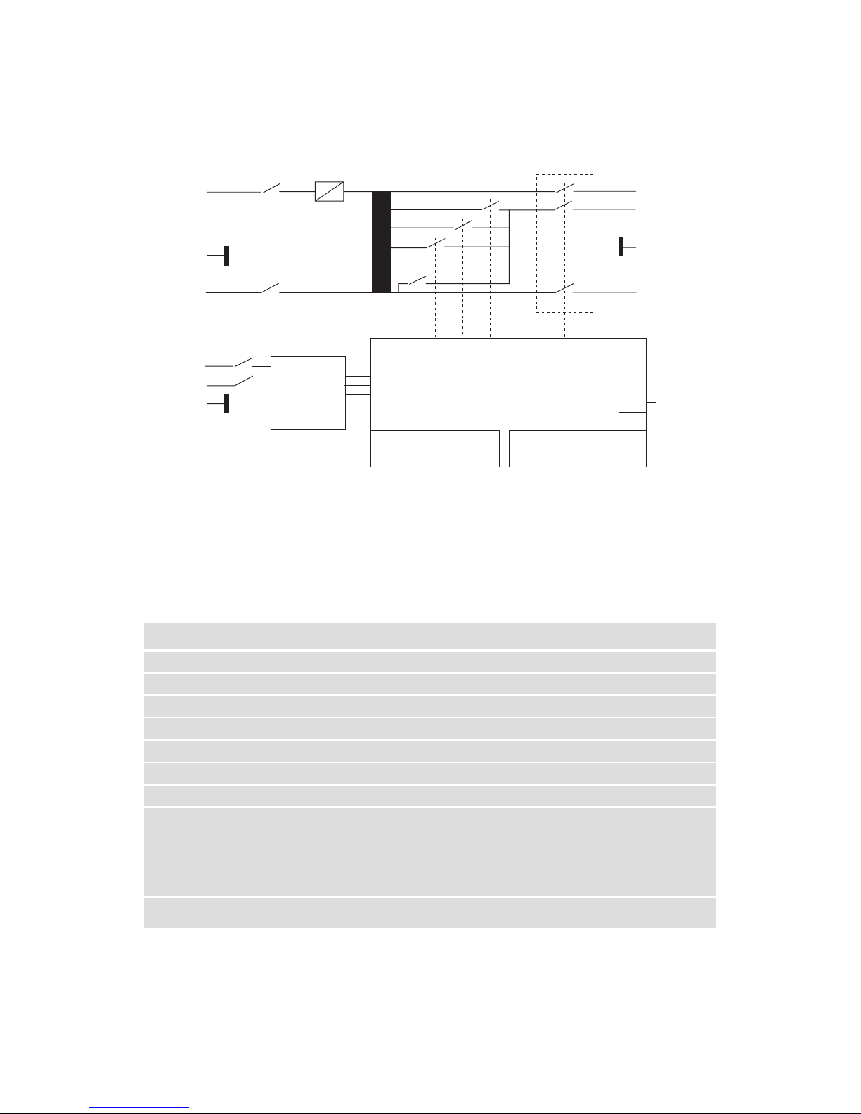
2.1 Circuit diagram INA 6502
L11
3
22
EUT
Power
IN
N.C
PE
N
EUTPowerON/OFF
16 AT
CircuitBreakerOption(CIB)
Instr.
Supply Power
Supply
0%40%70%80% EUTPower
ON/OFF
InterfaceController
PlugXI-SystemcableIN
25WaySubD–Male
PlugX2-SystemcableOUT
25WaySubD–Female
X
3
Uin
Uvar
PE
N
EUT
Power
OUT
Remote
Test+EUT
PowerOFF
ConnectiontoNSG
MaterControllervia
SystemInterfacecable
Terminationwith
Interlockplug
2.2 Technical specifications INA 6502
11EUTpowerON/OFFfunction FrontpanelswitchwithONindicator
Fuse 16A,slowblow
Connectors HartingtypeHAN3Acompatiblewith
NSG3000safelinkingconcept
Possibleextensions Interlockconnectiontodoorswitch
Ownsupply Selectable100-110V;220-240V15VA
Dimensions: LxWxH460x200x160mm
(18.1x7.9x6.3”)
Weight 15kg(33lbs)approx.
CablelengthtoNSG3000 2m(79”)
Inputcable NSG3000standardcabletobeused
Controlcable 2m-25waysubD–twistedpair-
shielded(includedindelivery)
Part designation Function
Mainssupplyinsocket Forinstrumentsupply,includesplug,
voltageselector(110V–230VAC),on/off
switchandfuse
EUTpowerinswitch SwitchestheEUTpowersupplyon/off
16ATfuse ProtectstheEUTpowersupplyline
EUTpowerinplug ForfeedingoftheEUTpower–useNSG
suppliedcableandconnectittopower
source(mains)
EUTpoweroutcable ConnectthiscabletotheEUTsupply
inputportoftheNSG
2.2.1 Parts description

12
Manual & automated step transformer INA 6501/INA 6502
Part designation Function
PlugX3 RemoteTESTandEUTpoweroff:with
shortingplug.Allowstoconectexternal
doorswitchorequivalent.
Interruptsthe24Vsupplyofthecircuit
breakercontactorwhichswitchesEUT
supplyon/off.
Theinformationwillbetransmittedto
NSG3000mastercontrollerwhichwill
stopthetest.
PlugX2 NSG3000systeminterfaceout–tobe
terminatedbyinterlockplugorlinkedto
anotheraccessory,toX1plug
PlugX1 NSG3000systeminterfacein–tobe
connectedtomastercontrollerorto
anotheraccessory,toX2plug
PowerLED(green) Showsifinstrumentispoweredup
ERRORLEDoff Noproblem-acessoryisreadytorun
ERRORLEDblinking Problemwhichmaybesolvedbyuser
intervention.Expl:Interlockisactivated
ERRORLEDon Problemwhichneedsmodulerepair
pleasecontactyournearestTeseq
customersupportcenterorsales
reprsentative
The equipment should be switched off during installa-
tion and interconnection.
2.3 Installation

13
Verifythesettingofinputvoltageselectorandadjustittotherightmainsvoltage
valueifrequired
Connectinstrumentpowerfromthemains
Remove25waySubDplugatrearofNSGorCDN
ConnectthisconnectortoX2ofINA6502
Connectmastercontroller25wayoutputtoINA6502X1plug,usingsystem
interfacecabledeliveredwithINA6502
ConnectINA6502-EUTpowerouttoEUTpowerinput
ConnectINA6502-EUTpowerintomainsusingEUTpowerincabledelivered
withNSGorCDN
Because of the capacitors in the internal coupler of CDN,
earth leakage currents of up to 4 A can occur in the EUT
power supply network. The test system must therefore
be correctly earthed and be powered from a supply that
is not protected by a residual current detector (RCD).
SwitchonINA6502rst
SwitchonNSG/CDNmainframe
SwitchonEUTpower(redswitch)whenpowerfortheEUTisrequired
EUTpowerouttoNSGorCDN
LEDindications
Terminationplug
Systemcableto
toNSGorCDN
EUTpowerOn/Offswitch
Mainspowerswitch
Mainspower
16 AT fuse
EUTpowerinconnection

To nd your local partner within
Teseq®’s global network, please go to
www.teseq.com
© May 2015 Teseq®
Specications subject to change without
notice. Teseq®, a unit of AMETEK
Compliance Test Solutions, is an ISO-
registered company. Its products are
designed and manufactured under the
strict quality and environmental require-
ments of the ISO 9001. This document
has been carefully checked. However,
Teseq® does not assume any liability for
errors or inaccuracies.
Manufacturer
Teseq AG
4542 Luterbach, Switzerland
T + 41 32 681 40 40
F + 41 32 681 40 48
chsales.teseq @ ametek.com
China
AMETEK Commercial
Enterprise (Shanghai) Co., Ltd.
Beijing Branch
T + 86 10 8526 2111
F + 86 10 8526 2141
chinasales @ teseq.com
France
AMETEK SAS
T + 33 1 30 68 89 00
F + 33 1 30 68 89 99
info.france @ ametek.com
Germany
Teseq GmbH
T + 49 30 5659 8835
F + 49 30 5659 8834
deinfo.teseq @ ametek.com
Japan
AMETEK Co., Ltd. Nagoya Ofce
T + 81 52 709 5501
F + 81 52 709 5502
cts-japan.sales @ ametek.co.jp
Singapore
AMETEK Singapore Pte Ltd
(C/o Teseq Pte Ltd)
T + 65 6484 2388
F + 65 6481 6588
singaporesales @ teseq.com
Switzerland
Teseq AG
T + 41 32 681 40 40
F + 41 32 681 40 48
chsales.teseq @ ametek.com
Taiwan
Teseq (Taiwan) Ltd.
T + 886 2 2917 8080
F + 886 2 2917 2626
taiwansales @ teseq.com
UK
Teseq Ltd.
T + 44 845 074 0660
F + 44 845 074 0656
uksales @ teseq.com
USA
Teseq Inc.
T + 1 732 417 0501
F + 1 732 417 0511
Toll free +1 888 417 0501
usasales.cts @ ametek.com
This manual suits for next models
1
Table of contents
Popular Transformer manuals by other brands

Titanium
Titanium TT-DR-CVB-100 manual

Wolf
Wolf ATEX Operation and maintenance instruction manual

Federal Signal Corporation
Federal Signal Corporation 2001-AC Description, Specifications, Installation, Operation, and Service Manual

Monacor
Monacor img Stage Line DIB-100 manual

France
France P5G-2ELP Series installation guide

Sealey
Sealey TR1000.V3 instructions


