Tetan KP 12S User manual

Automatic boiler
KP 12S KP 22S KP 62S
KP 12 –ES KP 22 –ES KP 62 - ES
Service and operation manual
www.tetan.ua

Automatic boiler for wood pellets
We would like to focus your attention mainly on the following chapters:
number 1 –Important notes
number 6 –Putting the product into operation
number 7 –Maintenance and attendance of the boiler during operation
The boiler has been approved for operation in the Czech Republic and in 27 EU countries by the State Testing
Institute, state testing plant number 202.
General information on CAA and smoke control
The Clean Air Act 1993 and Smoke Control Areas
Under the Clean Air Act local authorities may declare the whole or part of the district of the authority to be a
smoke control area. It is an offence to emit smoke from a chimney of a building, from a furnace or from any fixed
boiler if located in a designated smoke control area. It is also an offence to acquire an "unauthorised fuel" for use
within a smoke control area unless it is used in an "exempt" appliance ("exempted" from the controls which
generally apply in the smoke control area).
The Secretary of State for Environment, Food and Rural Affairs has powers under the Act to authorise smokeless
fuels or exempt appliances for use in smoke control areas in England. In Scotland and Wales this power rests
with Ministers in the devolved administrations for those countries. Separate legislation, the Clean Air (Northern
Ireland) Order 1981, applies in Northern Ireland. Therefore it is a requirement that fuels burnt or obtained for
use in smoke control areas have been "authorised" in Regulations and that appliances used to burn solid fuel in
those areas (other than "authorised" fuels) have been exempted by an Order made and signed by the Secretary
of State or Minister in the devolved administrations.
The KP12, KP22 and KP62 boilers have been recommended as suitable for use in smoke control areas when burning wood
pellet.
Further information on the requirements of the Clean Air Act can be found here :
http://smokecontrol.defra.gov.uk/
Your local authority is responsible for implementing the Clean Air Act 1993 including designation and supervision
of smoke control areas and you can contact them for details of Clean Air Act requirements.

Automatic boiler for wood pellets
2
CONTENT
COntent ......................................................................................................................................................2
pictures.......................................................................................................................................................3
TABle..........................................................................................................................................................4
1IMPORTANT NOTES ..............................................................................................................................5
2use of the boiler and its advantages........................................................................................................6
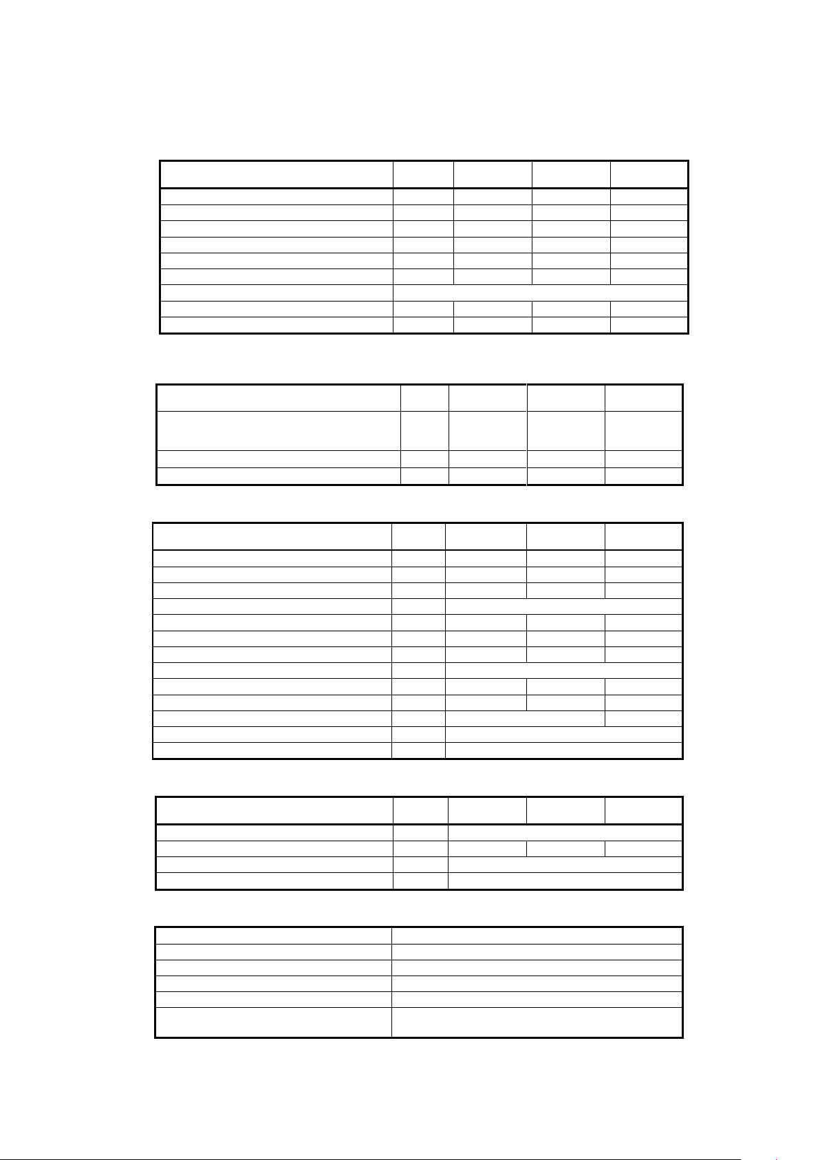
3Technical data of the boilers KP x2S, KP X2 - ES ......................................................................................7
4structural description of products............................................................................................................8
PICTURE OF PRODUCT AND MAIN PARTS......................................................................................................8
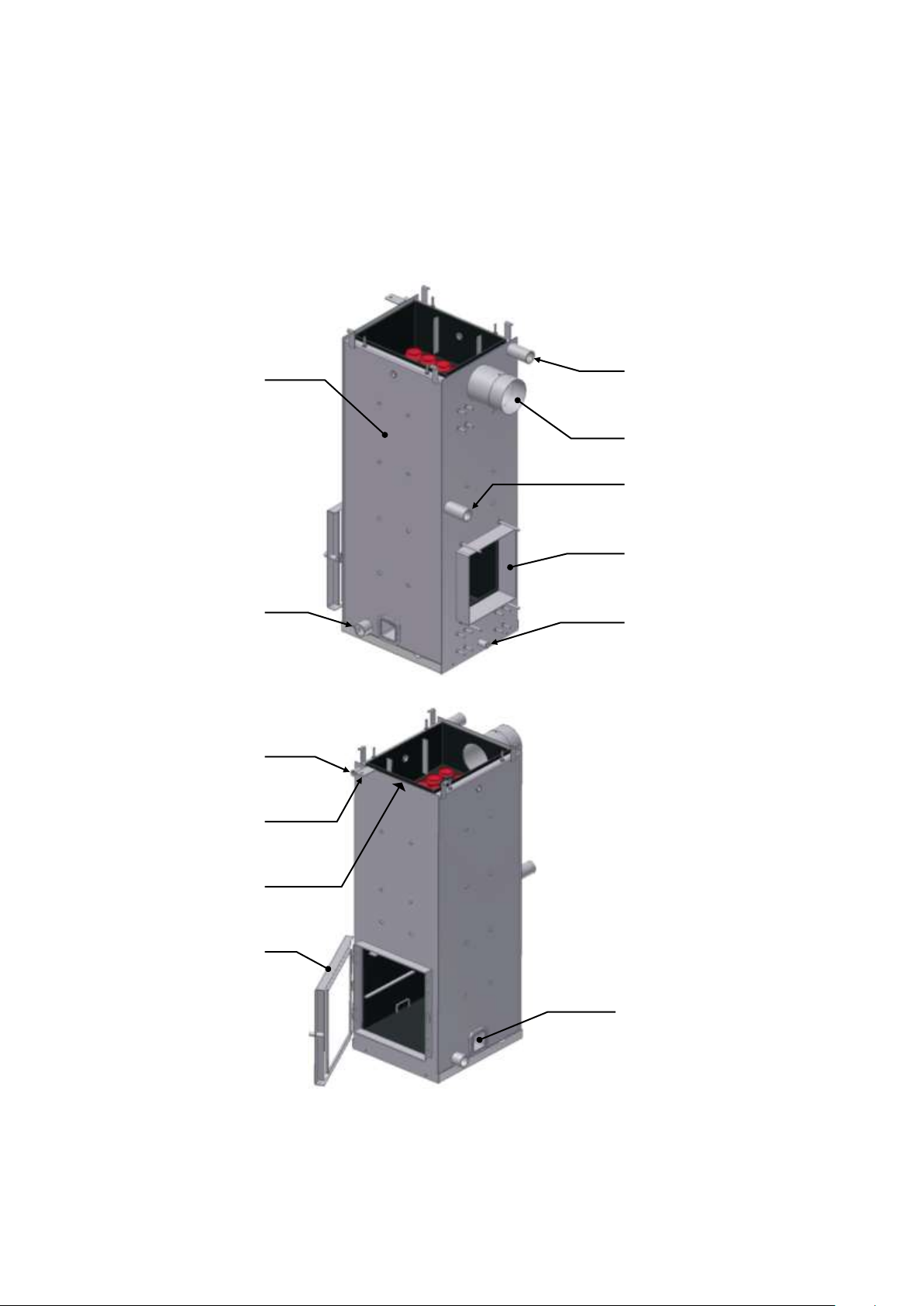
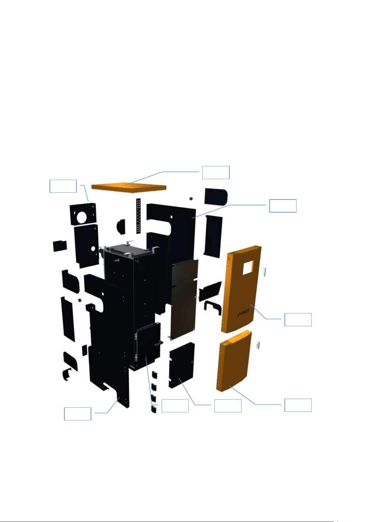
4.1 BOILER BODY, SCHEMA OF THE PRODUCTS AND DESCRIPTION OF THE MAIN PARTS.........................9
Boiler body..................................................................................................................................................9
4.2 CONTROL UNIT ............................................................................................................................10
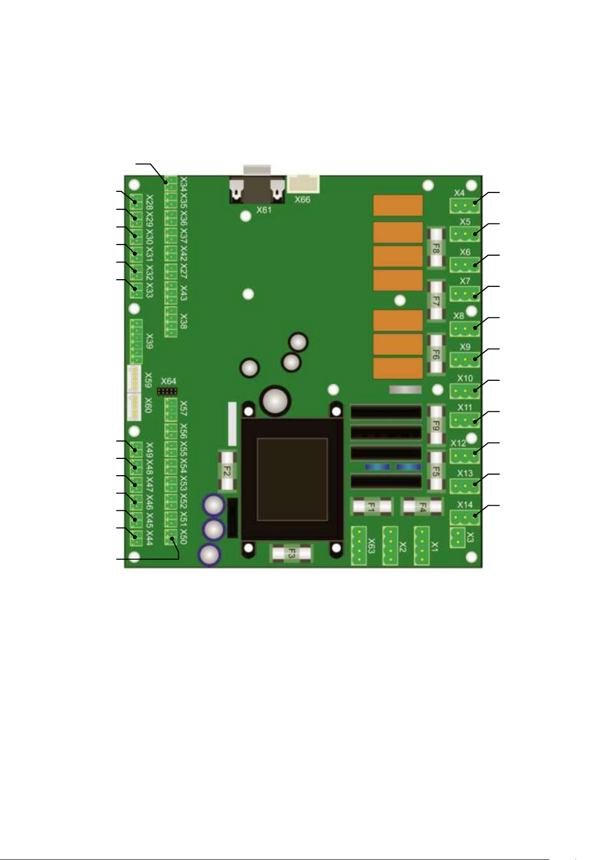
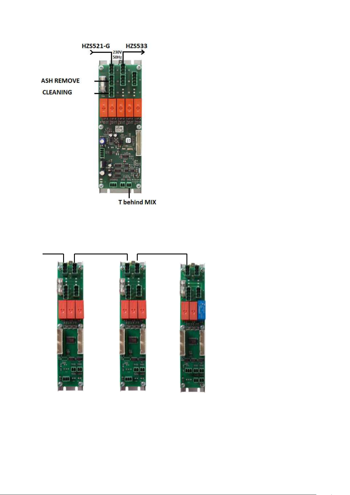
4.2.1 Boiler Function Module HZS 521-G........................................................................................11
4.2.1.1 Technical base data .........................................................................................................13
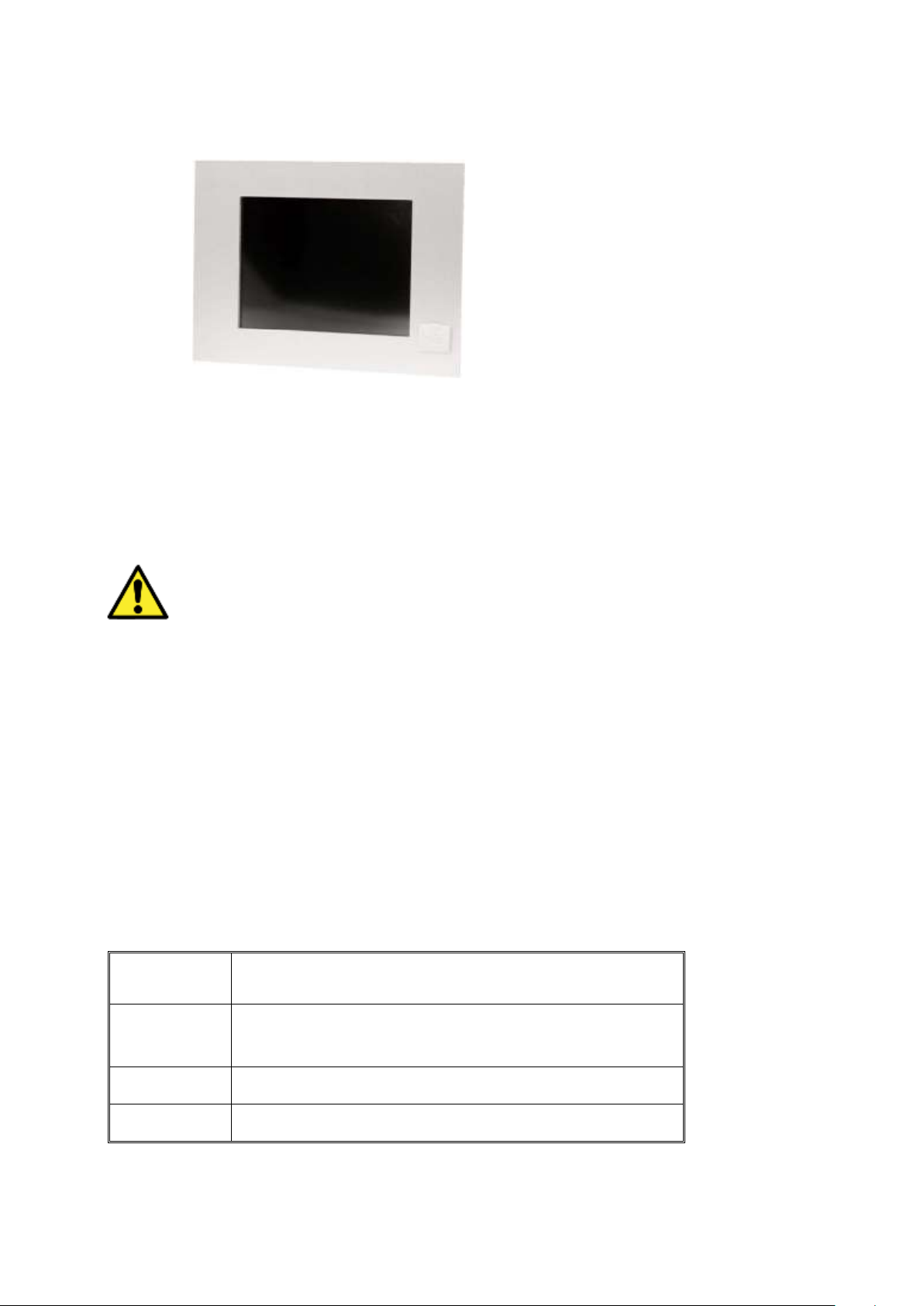
4.2.2 Terminal HZS 555-S with USB .............................................................................................14
4.2.2.1 Description......................................................................................................................14
CLEANING THE TOUCH SCREEN ..............................................................................................................14
CAUTION!...........................................................................................................................................14
Before cleaning the touch screen, the terminal must first be turned off to avoid unintentionally triggering
functions or commands!.......................................................................................................................14
4.2.2.2 Technical data.................................................................................................................14
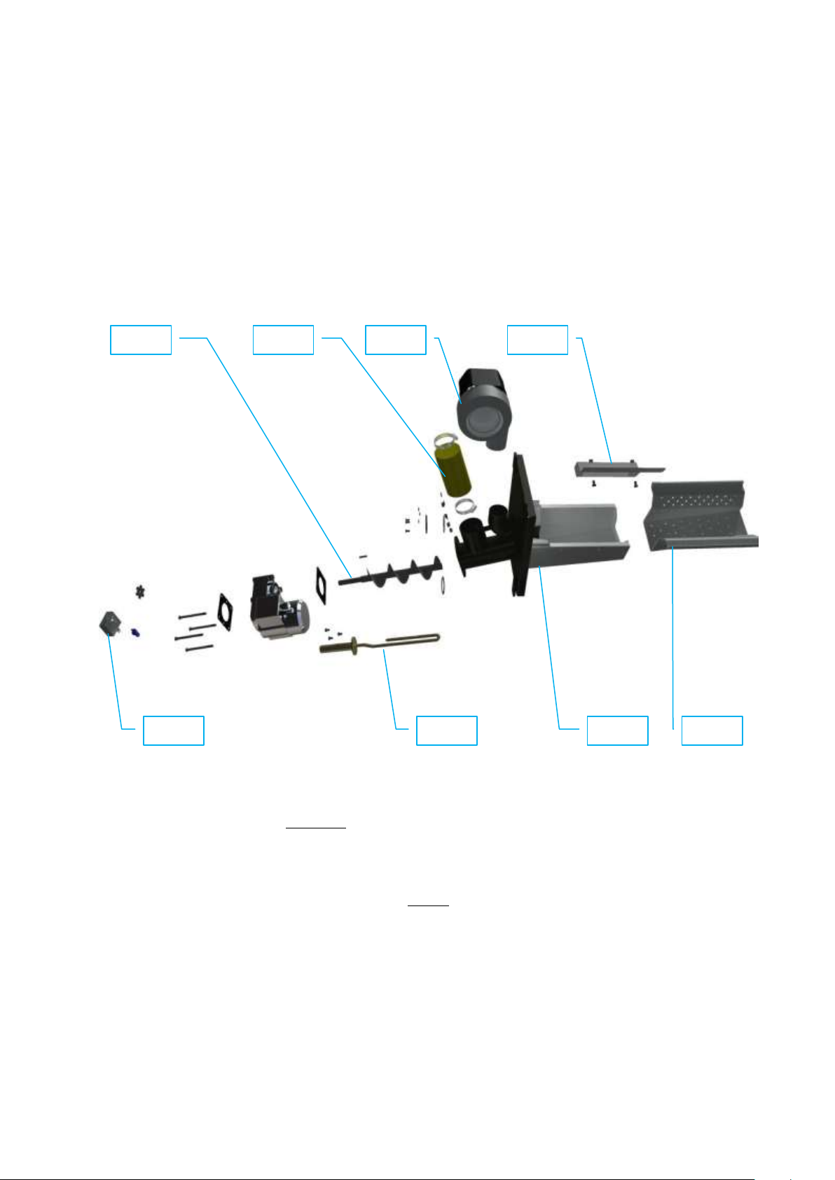
4.3 BURNER HEATING CHAMBER INCL. FEEDER F1 WITH INDEPENDENT DRIVE.....................................16
CERAMIC PARTS.....................................................................................................................................17
4.4 FEEDER F1 WITH INDEPENDENT DRIVE (FROM FUEL STORAGE)......................................................18
4.5 BOILER SHEATHING INCLUDING HEAT INSULATION.......................................................................19
4.6 CLEANING SYSTEM.......................................................................................................................22
4.6.1 Ash removal .......................................................................................................................22
4.6.2 Heat exchanger cleaning .....................................................................................................22
4.6.3 External ash container.........................................................................................................23
4.7 STANDARD ACCESSORIES.............................................................................................................24
4.8 OPTIONAL ACCESSORIES..............................................................................................................24
4.9 FUEL BIN .....................................................................................................................................24
5Placement OF THE PRODUCT IN BOILER ROOMS, PRINCIPLES OF INSTALLATION ...................................26
5.1 PLACEMENT OF PRODUCTS IN BOILER ROOMS...............................................................................26
5.2 SAFE DISTANCE FROM COMBUSTIBLE MATERIAL............................................................................26
5.3 LEGISLATION IN FORCE................................................................................................................26
4.1.1 Heating system and boiler ...................................................................................................26
4.1.2 Venting ..............................................................................................................................26
4.1.3 Fire regulations...................................................................................................................27
4.1.4 Electrical ............................................................................................................................27
4.1.5 Protection against noise.......................................................................................................27
5.4 STORAGE OF FUEL .......................................................................................................................27
5.5 BOILER ROOM VENTILATION ........................................................................................................27
6putting the PRODUCTS INTO OPERATION .............................................................................................28
6.1 CONNECTION TO THE SYSTEM......................................................................................................28
6.2 INSTALLATION OF THE BURNER....................................................................................................29
6.3 INSTALATION OF THE CERAMIC CATALYTIC REFLECTOR ................................................................30
6.4 INSTALLATION OF SECONDARY CERAMIC GRATE ...........................................................................31
6.5 INSTALLATION OF CERAMIC SHIELD .............................................................................................32
6.6 CONNECTION OF ELECTRICAL PARTS ............................................................................................32
6.7 CHECKING TASKS BEFORE BOILER FIRST OPERATION ....................................................................33
7boiler service and maintanance during operation....................................................................................34
7.1 SERVICE ......................................................................................................................................34
7.1.1 Refueling............................................................................................................................34
7.1.2 Emptying of the external container .......................................................................................34
7.1.3 Flue gases exchanger cleaning .............................................................................................35
7.2 MAINTANANCE.............................................................................................................................35
7.2.1 Burnt gases exchanger cleaning ...........................................................................................35
7.2.2 Burner grate cleaning ..........................................................................................................35
7.2.3 Ceramic grate cleaning ........................................................................................................35
7.2.4 Annual audit.......................................................................................................................36
8disposal of product after teh end of its service life..................................................................................38
8.1 NATURAL PERSON ........................................................................................................................38
8.2 LEGAL ENTITY..............................................................................................................................38

Automatic boiler for wood pellets
3
9control unit operation ..........................................................................................................................39
9.1 MAIN MENU .................................................................................................................................39
9.2 OPERATING CONDITIONS –MAIN MENU........................................................................................40
9.3 MAIN MENU .................................................................................................................................41
9.3.1 Setting menu......................................................................................................................41
9.3.1.1 Info menu.......................................................................................................................41
9.3.1.2 Menu users settings .........................................................................................................42
9.3.1.3 Menu 3 Servis..................................................................................................................45
9.3.2 Menu –heating circuits........................................................................................................55
9.3.2.1 Tank...............................................................................................................................56
9.3.2.2 Sanitary water.................................................................................................................58
9.3.2.3 Heating circuit .................................................................................................................60
9.4 ERROR - OVERHEATING, EMERGENCY THERMOSTAT ......................................................................63
9.5 ERROR - OVERHEATING, OPERATING THERMOMETER ....................................................................64
9.6 ERROR –OVERHEATING IN FUEL PATH..........................................................................................64
9.7 ERROR FROM LOW TEMPERATURE OF WATER OR COMBUSTION PRODUCTS....................................65
9.8 ERROR OF TEMPERATURE SENSOR CONTACT.................................................................................65
9.9 ERROR –EXCEEDED ALLOWED TIME OF FEEDER F1 AND F2 RUN ....................................................66
9.10 ERROR –EXCEEDED ALLOWED TIME OF FEEDER F1 AND F2 RUN.................................................66
9.11 ERROR –NOT IGNITED .............................................................................................................66
9.12 ERROR –LACK OF FUEL IN THE TANK ........................................................................................67
10 Power outage ..................................................................................................................................67
11 Guarantee and liability for defects .....................................................................................................67
PICTURES
Picture No. 1 Picture of product –main parts............................................................................................8
Picture No. 2 Boiler body........................................................................................................................9
Picture No. 3 Control unit ................................................................... Chyba! Záložka není definována.
Picture No. 4 Boiler Function Module HZS 521-G ....................................................................................11
Picture No.5 HZS 532-1.......................................................................................................................12
Picture No. 6 Other modules .................................................................................................................12
Picture No. 7 Terminal with USB............................................................................................................14
Picture No. 8 Burner.............................................................................................................................16
Picture No. 9 Cer. reflektor KP 12, KP 22 ...............................................................................................17
Picture No. 10 Two-part cer. reflektor KP 62............................................................................................17
Picture No. 11 Ceramic secondary grade .................................................................................................17
Picture No. 12 Ceramic shield.................................................................................................................17
Picture No. 13 Ceramic door casing.........................................................................................................17
Picture No. 14 Feeder F1 .......................................................................................................................18
Picture No. 15 Jacketing KP 12S, KP 12 - ES ...........................................................................................19
Picture No. 16 Jacketing KP 22S, KP 22 - ES ...........................................................................................20
Picture No. 17 Jacketing KP 62S, KP 62 - ES ...........................................................................................21
Picture No. 18 Ash removal system.........................................................................................................22
Picture No. 19 Exchanger ash container ..................................................................................................23
Picture No. 20 External ash container......................................................................................................23
Picture No. 21 Standard fuel bin sizes .....................................................................................................25
Picture No. 22 Assembly guide ...............................................................................................................25
Picture No. 23 Required chimney draft ....................................................................................................27
Picture No. 24 Installation dimension of boiler .........................................................................................28
Picture No. 25 Burner installation............................................................................................................29
Picture No. 26 Ceramic reflektor ...........................................................................................................30
Picture No. 27 Parts of secondary ceramic grate ......................................................................................31
Picture No. 28 Ceramic grate parts placement guide ................................................................................31
Picture No. 29 Ceramic shield.................................................................................................................32
Picture No. 30 Ceramic top placement guide............................................................................................32
Picture No. 31 Main menu –sample of visualisation.................................................................................39
Picture No. 32 Principle of the modulation...............................................................................................69
Picture No. 33 Dim. Req. for the placement of KPx2 in boiler room –exam. of using collecting troughs .......70
Picture No. 34 Directory information - consuption wood pellets for boiler family KP .....................................71
Picture No. 35 Circuit diagram –control unit............................................................................................72
Picture No. 36 Circuit diagram + modul HZS 533 ....................................................................................73
Picture No. 37 Circuit diagram - HZS 533, HZS 535 ................................................................................74

Automatic boiler for wood pellets
4
TABLE
Table 1 Thermal and technical parameters of products ...............................................................................7
Table 2 Solid harmful substances in combustion........................................................................................7
Table 3 Technical parameters of products ................................................................................................7
Table 4 Electrical parameters of products .................................................................................................7
Table 5 Fuel and its parameters...............................................................................................................7
Table 6 Settings - Service .....................................................................................................................75

Automatic boiler for wood pellets
5
1IMPORTANT NOTES
This product may only be put into operation by an installation organization trained by the manufacturer.
This product may only be operated by adult persons, duly acquainted with the way the product is controlled and
duly acquainted also with these Instructions. If you adhere to the below mentioned principles, the product will
serve you reliably to your full satisfaction.
1) It is prohibited to intervene in any way in the structure or electrical installation of products. Having the
equipment been disconnected from the electric network, the power supply cord has to be plugged from
the mains outlet.
2) It is prohibited to use inflammable liquids for ignition.
3) No inflammable materials may be stored on the boiler, neither may they be stored within the distance of
1,500 mm from the boiler (except for operating metal fuel bin).
4) In order to preserve long-term service life of the boiler body, it is not recommended to operate the boiler
frequently under the temperature of 55°C, if the boiler is not protected with a primary circuit. The
temperature of 55°C should be considered as the minimum temperature.
5) The check how the boiler is filled with fuel is only visual. Any verification with touch is prohibited as it
may result in injury.
6) Never open door of the boiler if there is a ignition process.
7) The door of the boiler has to be always tightly closed. If you´ll perform any check, open the door
carefully to prevent from getting jeopardized by gathered products of combustion or to prevent any
sparks flying out from the boiler from being the cause of any accident. Open the door slowly in order to
get the combustion chamber aerated towards the chimney. This procedure has to be adhered to when
the ash is being removed from the ash pan's space.
8) If any work which generates inflammable vapours takes place in the boiler room (glueing the floor, etc.),
the boiler has to be out of operation and the fire has to be burnt out in the boiler.
9) Having the heating season been finished, clean the boiler thoroughly as per the chapter 7 - Maintenance.
Products of combustion stuck to the walls of the exchanger may act corrosively for the whole period of
time when the boiler will be out of operation. If the burner is not cleaned, this may have effect on faulty
combustion. We recommend to hire a specialized company to perform this work.
10) If you work on or near to the mechanically movable parts (fuel feeder, etc.), ensure safe disconnection of
the equipment from electric voltage. There is a risk of injury.
11) You should always operate the boiler only under parameters and in harmony with recommendations
given in these instructions for installation and operation. If the boiler works in the AUTO mode and if
there is a failure of current, the boiler will start operation again with the electric firing programme (if this
programme has been installed) after the delivery of electric current is restored.
12) The manufacturer does not assume any liability for errors and subsequent damage caused by unskilled
operation of the equipment or by infringement of principles given in these instructions for installation and
operation or by infringement of generally binding standards and regulations or by using inadequate fuel.
13) If the boiler is moved or otherwise handled with, safety regulations which apply to handling with heavy
loads have to be adhered to.
14) It is prohibited to place heavy loads on jacketing boiler and to step on it. It is recommended to remove
the protective foil after all the building and installation work has been completely finished.
15) External ashtray has to be firmly connected to a boiler fitting while in the operation. Cover of this ashtray
has to be tightly closed. There could be a dangerous escape of combustion gases into a boiler room.

Automatic boiler for wood pellets
6
2USE OF THE BOILER AND ITS ADVANTAGES
The series of automatic hot-water boilers for wood pellets is designed mainly to heat family houses, small
municipal buildings, cottages and small plants or business buildings.
The main advantages of products:
1) AUTOMATIC OPERATION ensured by the control unit which cooperates with the indoor thermostat,
thermostat of SW tank for hot watter, outside thermometer in the mode of equitherm regulation,
eventually by superior control system, which ensures comfort for the user including maximum saving of
fuel.
2) Automatic ASH REMOVING and heat EXCHANGER CLEANING ensures a long time maintanance free and
maximum comfort of heating while keeping high burning efficiency.
3) CONTROL UNIT with modern design –controls operation of the boiler, ensures automatic operation, high
operational reliability and long distance control.
Color TFT display 5,7" with touch screen.
Remote control over TCP/IP
USB
User friendly controling
Operation modes: Equitherm, Modulation or Fixed power
Two heating circuits and sanitary water in basic configuration
Possibility to controll acumulation tank or solar system –maximum 7 heating circuits
Upgrading software over USB bootstick
4) PRIORITY HEATING of sanitary water –is secured by the structure and software package of the boiler
without any need for other control elemets.
5) MODULATION PERFORMANCE of the boiler allows adjust production of the heat to an actual needs of the
building.
6) Heating in EQUITHERM regulation mode lowers the cost of the heating.
7) The burner system used with two independent feeders and with a system of ceramic catalytic reflector
and grate ensures perfect SMOKELESS FUEL COMBUSTION, which supports high thermal efficiency of the
product and also excellent ecological parametrs with the minimum content of harmful sustances in
combustion products (20-50x less than conventional boilers).
8) SAFETY OF OPERATION ensured by separated structure of fuel transport routes and by the selected
transport mode.
9) The boiler makes it possible to ensure ANTIFREEZE PROTECTION of heating system in building by a
suitably selected system using electric power.
10) DESIGN AND SURFACE –jacketing of the products is coated with a heavy-duty COMAXITE COATING
which is perfectly resistant to environment effects and ensures perfect appearance of products on long-
term basis. Design of whole solution is using a modern shape elements.
11) This SUBSIDIED ABLE PRODUCT –is fullfilling all required conditions for obtaining subsidies in many
states of the European Union.
12) LONG DISTANCE CONTROL and monitoring by internet or GSM connection.

Automatic boiler for wood pellets
7
3TECHNICAL DATA OF THE BOILERS KP X2S, KP X2 - ES
Table 1 Thermal and technical parameters of products
Parameter
Unit
KP 12S
KP 12 - ES
KP 22S
KP 22 - ES
KP 62S
KP 62 - ES
Rated output
kW
19
29
62
Output range
kW
5,5 - 19
8 - 29
18 - 62
Fuel consumption
kg x hrs.-1
~1,3 - 4,4
~1,9 - 6,6
~4,1 –14,28
Efficiency (rated output)
%
91,2
90,9
90,6
Efficiency (minimum output)
%
90,1
90,1
90,1
Temperature of combustion products
°C
94 - 151
94 - 148
94 - 140
Class of the boiler
3
Hours of burning - min/max –fuel bin 400L
hrs
213 –61
142 - 40
64 - 19
Hours of burning - min/max –fuel bin 700L
hrs
373 –107
249 - 70
111 –33
*in heating value 17,5MJ/Kg and efficiency 90%
Table 2 Solid harmful substances in combustion
Parameter
Unit
KP 12S
KP 12 - ES
KP 22S
KP 22 - ES
KP 62S
KP 62 - ES
Average mass flow rate solid elements
pollutions at rated power
g*hrs-1
0,36
0,65
2,2
Exhaust mass flow rate on the outlet-nominal output
kg/s
0,012
0,018
0,034
Exhaust mass flow rate on the outlet-reduced output
kg/s
0,005
0,007
0,016
Table 3 Technical parameters of products
Parameter
Unit
KP 12S
KP 12 - ES
KP 22S
KP 22 - ES
KP 62S
KP 62 - ES
Weight
kg
310
370
590
Water content
litres
55
70
160
Fume duct diameter
Mm
130
150
160
Connections: heating and return water
Js
G 1 1/2"
Heating surface
m2
1,8
2,1
3,2
Dimensions (w + d) without ashtray
mm
477x 980
614x980
845x1360
Dimensions (h)
mm
1435
1435
1720
Working overpressure of water
bar
in to 2,5
Hydraul. loss ΔT 10 K
mbar
4,77
10,97
33,7
Hydraul. loss ΔT 20 K
mbar
1,26
2,77
8,3
Required chimney draft
mbar
0,1 –0,2
0,3 –0,4
Recom. operating temp. of heating water
°C
60 –80
Lowest temperature of incoming water
°C
55
Table 4 Electrical parameters of products
Parameter
Unit
KP 12S
KP 12 - ES
KP 22S
KP 22 - ES
KP 62S
KP 62 - ES
Connecting voltage
230 VAC ± 10%, 50 Hz ± 2 Hz
Electric input (4 motors, fan)
W
180
210
340
El. Protection of the control unit
---
IP 54
El. Protection of the boiler´s wiring
---
IP 20
Table 5 Fuel and its parameters
Wood pellets diameter
6,0 - 8,5 mm
Caloric value
approximately 16-18 MJ / kg
Water content
Up to 10 %
Ash content
Up to 1 % ( 0,8 –1,0% )
Bulk weight
0,6 –0,64 kg / dm3
Fuel delivery system
PE/PP bags 15 –25 kg,
bags Big Bag by 800 - 1100 kg, cistern filled
As a guaranteed fuels for all KP boilers are wood pellets, with parameters specified in table 5.

Automatic boiler for wood pellets
8
4STRUCTURAL DESCRIPTION OF PRODUCTS
The structure adheres to the Czech standard ČSN – EN 303.5 / 2000 i.e. boilers for central heating -
part 5 (boilers for central heating with automatic fuel feed of rated heat output up to 300 kW).
PRODUCT MAIN PARTS –front side
PRODUCT MAIN PARTS –back side
Picture No. 1 Picture of product –main parts
Control unit –boiler function modules
External ashtray
Connection flexible hose
Primary fan
Boiler cover
Terminal with USB
Cleaning mechanism
Inspection door
Cleaning motor
Feeder F2
Exhaust pipe
Heating water output
Feeder F1
Backwater input

Automatic boiler for wood pellets
9
4.1 BOILER BODY, SCHEME OF THE PRODUCTS
AND DESCRIPTION OF THE MAIN PARTS
BOILER BODY
is made of top-quality steel metal sheets and pipes for boiler in form of a weldment. Its shape is adapted in such
a way so that combustion products are cooled down efficiently at individual levels of power output, which is,
moreover, assisted by a system of turbulators. The exchanger is shaped in such a way so that the exhaust pipes
of combustion products can be cleaned individually and efficiently.
Picture No. 2 Boiler body
Steel weldment
with heat exchanger
Inspection door
Exhaust pipe 130, 150 or 160 mm
Heating water output water G 1½“
(inside thread)
Backwater input water G 1½“
(inside thread)
Rear flanged hole
to install the burner system
Pipe G ½“ to install filling valve
Pipe with inside thread M48x2
mm to install an electrical
heating unit (optional)
Flanged hole to install ash
removing system
Openig on top for cleaning
covered by a lid of the
boiler´s body
Thermowell for sensor
and thermostat
Emergency thermostat holder

Automatic boiler for wood pellets
10
4.2 CONTROL UNIT
Boiler is equipped with the control system with touch screen. This control system enables automatic boiler
operation through the control and regulation features (thermostats, sensors, etc.) in the requested modes. It also
enables Diagnostics mode of control, which can be used for instance for boiler commisioning.
The control system construction and its electrical shielding (IP 45) make safe and reliable operation possible even
under the demanding operational and climatic conditions common to boiler rooms.
Basic configuration Optional configuration
Configuration:
Name
Type
Options
Order code
Control unit - boiler function module
HZS 521-G
Standard
Terminal (touchscreen)
HZS 555-S
Standard
Module extension
HZS 532-1
Standard
Module heating circuit / acumulation tank
HZS533
Optional
Module solar
HZS535
Optional
Type and number of circuit
Type and number of module
HC1
SWT
HZS 521-G
HZS532-1
HC1
HC2
SWT
HZS 521-G
HZS532-1
HC1
HC2
HC3
SWT
HZS 521-G
HZS532-1
1 pc
HZS 533
HC1
HC2
HC3
HC4
SWT
HZS 521-G
HZS532-1
2pcs
HZS 533
HC1
HC2
HC3
HC4
HC5
SWT
HZS 521-G
HZS532-1
3pcs
HZS 533
HC1
HC2
HC3
HC4
HC5
ACU
HZS 521-G
HZS532-1
3pcs
HZS 533
HC1
HC2
HC3
HC4
ACU
SOL
HZS 521-G
HZS532-1
2pcs
HZS 533
HZS 535
HC –heating circuit
SWT –sanitary water tank
ACU –acumulation tank
SOL –solar systém
Terminal
HZS 555-S
Boiler function module
HZS 521-G
Extension m.
HZS 532-1
Module
HZS 533
Module
HZS 533
Module
HZS 533

Automatic boiler for wood pellets
11
4.2.1 Boiler Function Module HZS 521-G
The heating system is modularly constructed. The HZS 521-G is a module for the boiler, which communicates
with the CPU module and executes the transmitted instructions. The HZS is a simple component that is used to
control automated processes in a heating system.
All interfaces and connections for controlling of the boiler are located on the control board.
Picture No. 3 HZS 521-G Connector and terminal electronics layout
The control unit always contains modules HZS 521-G a HZS 532-1.
Ambient temperature sensor
HC1 mix temp
Backwater temp
Sanitary water temp
Exhaust temp
Sanitary water top
Sanitary water bottom
Room thermostat 3
Room thermostat 2
SWT thermostat
Room thermostat 1
Impulse sensor 1
Impulse sensor 2
Room thermostat 4
Antifrost protection
Servo open
Servo close
SWT pump
Bypass pump
Ignition
HC1 pump
Primary fan
Exhaust fan
Feeder 1
Feeder 2

Automatic boiler for wood pellets
12
Picture No.4 HZS 532-1
HZS533 HZS533 HZS535
Picture No. 5 Other modules

Automatic boiler for wood pellets
13
4.2.1.1Technical base data
HZS521-G
Supply voltage
230 V AC +/- 10 %
(Input voltage for the power transformer on the power board, input
voltage for the STB, phase for the phase angle, relays and Triac outputs)
Power supply fre-
quency
45 - 65 Hz
Current
consumption of
supply (230 V AC)
Total current consumption 200 mA + current consumption of the
connected loads (max. 16 A)
Power supply transformer
Supply for the power board and CPU electronics
Supply for Heater Lambda sensor: 200 mA
The power supply is switched of STB, L-STB
Loads connected over fuse F4 (3,15 AT):
X11 primary fan: maximum
690 W/ maximum 3 A
Loads connected over fuse F5 (10 AT):
X14
Screw: maximum 690W/ maximum 3 A
Loads connected over fuse F6 (10 AT):
X9 Turbine: maximum 2300 W/ maximum 10 A
Loads connected over fuse F7 (10 AT):
X8 Ignition: maximum 2300 W/ maximum 10 A
Loads connected over fuse F8 (10 AT):
X5 heat exchange cleaner: maximum 690 W/ maximum 3 A
X6 grate open: maximum 690 W/ maximum 3 A
X7 grate closed: maximum 690 W/ maximum 3 A
The power supply not switched over STB, L
Loads connected over fuse
F9 (10 AT):
X10 boiler circuit return flow pump: maximum 2300 W/ maximum 10 A
HZS532-1
Internal
electronics power
supply
+24 V (from HZS 511), must be connected to the expansion
controller
Relay power
supply
230 VAC
Fuse
10 A for relay outputs
+24 V current
consumption
HZS 532-1: maximum 60 mA (without relays) Maximum
120 mA (with relays) HZS 532-1 with 5 expansion modules,
maximum 350 mA
HZS533, HZS535
Internal
electronics power
supply
+24 V (from HZS 511), must be connected to the expansion
controller
Relay power
supply
230 VAC
Fuse
5 A for relay outputs and/or 3 A for solar module
+24V current
consumption
HZS 533 maximum 15 mA (without relays) Maximum 40
mA (with relays)

Automatic boiler for wood pellets
14
4.2.2 Terminal HZS 555-S with USB
Picture No. 6 Terminal with USB
4.2.2.1Description
The HZS 555-S is an intelligent terminal for programming and visualization of automated processes. Process
diagnosis as well as operating and monitoring automated procedures is simplified using this terminal.
A touch screen serves as the input medium for process data and parameters. The output is shown on a 5.7"
SVGA TFT color display.
Cleaning the Touch Screen
CAUTION!
Before cleaning the touch screen, the terminal must first be turned off to avoid unintentionally
triggering functions or commands!
The terminal's touch screen can only be cleaned with a soft, damp cloth. To dampen the cloth, a screen-cleaning
solution such as an antistatic foam, water with detergent or alcohol should be used. First spray the cleaning fluid
on the cloth and not directly on the terminal. The cleaning solution should not be allowed to reach the terminal
electronics, for example, through the ventilation slots.
No erosive cleaning solutions, chemicals, abrasive cleansers or hard objects that can scratch or damage the
touch screen may be used.
If the terminal is soiled with toxic or acidic chemicals, quickly and carefully clean the terminal to prevent
corrosion.
4.2.2.2 Technical data
Supply voltage
Typically +24 V DC
MIN +18V DC MAX +30V DC
Current
consumption of
voltage supply
Typically 440 mA (pro + 24 V) ,
Maximum 650 mA
Stadby
Typically 0.56 W
Starting current
Maximum 25 A for 20 μs

Automatic boiler for wood pellets
15
Display
Type
5.7" LCD color display
resolution
VGA 640 x 480 Pixel
Color depth
18-bit RGB (262K colors)
LCD Mode
TN / normal white
LCD Polarizer
Transmissive
Pixel size
0.18 mm x 0.18 mm
Active surface
115.2 mm x 86.4 mm
Background lighting
LED
Contrast
600
Brightness
Typically 350 cd/m²
Angle CR >= 10
Left, right, below 75°, above 60°
Environmental conditions
Storage temperature
-10 –+85 °C
Operating temperature
0 –50 °C
Humidity
10 - 90 %, uncondensed
EMV stability
EN 61000-6-2: noise immunity
EN 61000-6-4: noise emission
Vibration - tolerance
EN 600068-2-6
2 - 9 Hz: Amplitude 3.5 mm
9 –200 Hz: 1 g (10 m/s²)
Shock resistance
EN 60068-2-27
15 g (150 m/s²)
Délka 11 ms, 18 rázů
Protection Type
EN 60529 Protected
through the housing
Front: IP54
Cover: IP20

Automatic boiler for wood pellets
16
4.3 BURNER HEATING CHAMBER INCL. FEEDER F1 WITH INDEPENDENT
DRIVE
The heating chamber is depicted in picture Nr. 1 and is comprises of these parts:
4.3.1 The burner body
4.3.2 Feeder F2 including the drive
4.3.3 Impulse sensor
4.3.4 Flexible hose
4.3.5 Primary fan
4.3.6 Electric resistence spiral for automatic ignition
4.3.7 Cover of spiral
4.3.8 Burner grate
Picture No. 7 Burner
The burner body –is a hollow weldment made from highly legated material with a bottom transversal fuel inlet.
The fuel is delivered by a built-in
F2 feeder
driven by an electric motor with a gearbox.
A set of slit and round jets in the burning grill ensures inflow of air in order to facilitate controlled full burning of
delivered fuel during its stay in the burner chamber. The burned out fuel is subsequently pushed over the edge of
the chamber into the ash receiver.
The inner space of the burner body is connected to an
air fan
, whose revolutions can be regulated within a large
range depending on the required boiler output or the type of fuel being used. (See MENU 11.9 Fans –chapter
9.4.9).
Impulse revolution sensor
The gearboxes of the F1 and F2 feeders are equipped with impulse sensors, which ensure safe operation of the
boiler.
Connecting hose to the F1 feeder made of inflammable material connect Feeder F1 and Feeder F2. It is part
of the transfer fuel lines. It must meet strict installation rules:
It cannot have significant folds, which would block smooth fuel movement and must be built with an
inclination of minimum 50º (in a relation to horizontal plane).
4.3.3
4.3.1
4.3.8
4.3.2
4.3.4
4.3.5
4.3.6
4.3.7

Automatic boiler for wood pellets
17
Attachment to both adaptors must be tight.
Cleaning of KP62 burner provides removal of excessive ash or cinder volume from the burner when burning
lower quality fuel. The drive of the cleaning mechanism is works together with ash cleaning.
Note:
Use of alternate fuels requires change of the burner type and also change of boiler program setup.
Note:
The cleaning mechanism burner drive and its installation are depicted in chapter 4.7 –Cleaning system.
CERAMIC PARTS
These parts are an inseparable component of the combustion chamber of the boiler and
they have a major influence on the quality of burning.
4.4.1 Ceramic reflector –placed on the top of the burner
4.4.2 Ceramic secondary grate –placed in the boiler body above the burner heating chamber
4.4.3 Ceramic plate –placed above the door
4.4.4 Ceramic door jacketing–mounted on the door
Picture No. 8 Cer. reflektor KP 12, KP 22
Picture No. 9 Two-part cer. reflektor KP 62
Picture No. 10 Ceramic secondary grade
Picture No. 11 Ceramic shield
Picture No. 12 Ceramic door casing

Automatic boiler for wood pellets
18
4.4 FEEDER F1 WITH INDEPENDENT DRIVE (FROM FUEL STORAGE)
F1 feeder delivers fuel from fuel storage to the burning chamber. It comprises of a pipe delivery path with an
overflow part and an end sleeve. The feeder is built into the fuel storage under an angle, which cannot exceed
45º. If the angle was any bigger, fuel could be dispensed inaccurately. The transporter has its own electric drive,
which is controlled by the control unit. The feeder is supplied in various lengths accommodating specific types of
storage tanks.
Feeder F1 and F2 gearboxes are equipped with impulse sensors, which ensure safe operation of the boiler.
Feeder F1 set comprises of:
4.5.1 Body of feeder with flange
4.5.2 Axle-less spiral (diameter 38mm in KP 12S, KP 12 - ES, KP 22S, KP 22 –ES; diameter 56mm in
KP 62S, KP 62 - ES)
4.5.3 A small bar for mounting of the spiral
4.5.4 Motor and gearbox
4.5.5 Impulse revolution sensor
Picture No. 13 Feeder F1
4.5.1
4.5.2
4.5.3
4.5.4
4.5.5

Automatic boiler for wood pellets
19
4.5 BOILER SHEATHING INCLUDING HEAT INSULATION
The product sheathing is manufactured from steel sheet metal. It is painted with durable paint applied with the
powder painting technology (KOMAXIT), which is highly resistant to outside conditions and ensures long-term
perfect look of the product. Heat insulation 2 or 8 cm thick is done with heat insulation ROCKWOL boards.
The sheathing consists of the following parts:
4.6.1. Left side plate –including coverings
4.6.2. Right side plate –including coverings
4.6.3. Upper cover
4.6.4. Front lower cover
4.6.5. Front upper coverí
4.6.6. Back cover –including covering
4.6.7. Door cover
4.6.8. Door
Picture No. 14 Jacketing KP 12S, KP 12 - ES
4.6.1
4.6.2
4.6.3
4.6.4
4.6.7
4.6.8
4.6.5
4.6.6
This manual suits for next models
5
Table of contents
Popular Boiler manuals by other brands

Atlantic Boilers
Atlantic Boilers BK50 Operating & maintenance instructions

Alde
Alde Comfort 2928 Instructions for use

Windhager
Windhager BioWIN XL operating manual

Worcester
Worcester GREENSTAR CDI C13 User instructions

Riello
Riello TAU 350 N INSTALLATION, TECHNICAL ASSISTANCE SERVICE AND SYSTEM MANAGEMENT MANUAL

Baxi
Baxi CBP Matic 18 manual

iQe
iQe COMFORT 30 Installation and servicing instructions

Crown Boiler
Crown Boiler BWC Series installation instructions

Dunkirk
Dunkirk 90-50 installation manual

Lennox
Lennox GWM-050IE installation instructions

Laars
Laars MagnaTherm HTD Series Installation and operation instructions

Ariston
Ariston CLAS EVO SYSTEM 24 CF Product guide