THAT CORPORATION THAT1570 User manual

THAT1570/THAT5171
Digitally-Controlled Microphone Preamplifier
Demo Board
User's Guide
Document 600134 Rev 02
Contents
Features/Specifications....................................................................................... 3
Overview ............................................................................................................ 4
Connections ....................................................................................................... 5
Hardware Set-up ................................................................................................. 5
Software Set-up ................................................................................................... 6
Operation ........................................................................................................... 7
Jumper Options ................................................................................................. 7
Appendix A - Schematic...................................................................................... 9
Appendix B - Bill of Materials............................................................................. 10
Appendix C - PCB Layout .................................................................................. 12
THAT Corporation; 45 Sumner Street; Milford, MA 01757-1656; US
A
Tel: +1 508 478 9200; Fax: +1 508 478 0990; Web: www.thatcorp.com
Copyright © 2009, THAT Corporation; All rights reserved.

Packing List
(1) THAT1570/5171 DEMO Board PCB Assembly
(1) USB Cable
(1) Software CD
If you are missing any of the above items please contact us at
FCC Warning
This device is only intended for laboratory test environments. It may radiate radio
frequency energy and has not been tested for compliance with subpart J of part
15 of the FCC regulations. Operation of this device in other environments may
cause interference with radio communications.
Document 600134 Rev 02 Page 2 of 16 THAT 1570/5171-DEMO User’s Guide
THAT Corporation; 45 Sumner Street; Milford, MA 01757-1656; US
A
Tel: +1 508 478 9200; Fax: +1 508 478 0990; Web: www.thatcorp.com
Copyright © 2009, THAT Corporation; All rights reserved.

Features
• “Combo” XLR/TRS balanced input with switchable 48V phantom power
• Balanced audio output on XLR and TRS connectors
• Supports pro audio signal levels: +21dBu input / output
• Gain (measured input to output) adjustable in 1dB steps: 0dB, and 8-63dB
• USB 1.1 and USB 2.0 compatible control port
• Graphical user interface software for controlling 5171 parameters
• Prototyping area
Description
The THAT Digitally-Controlled Mic Preamp Demo Board allows developers to
evaluate the performance of the THAT1570 / THAT5171 chipset. The demo
board provides a balanced audio input on a Neutrik “combo” connector with 48V
phantom power, and a balanced audio output on XLR and ¼” TRS connectors.
The supplied graphical user interface (GUI) controls all functions in the 5171 chip
via USB. A prototyping area is available for adding or modifying circuitry.
Specifications
mA
23 (V+ supply)
23 (V- supply)
0.5 (+5V supply)
ICC; -IEE, IDD
Supply Current
nV/√Hz
1.65 (60dB gain)
1.9 (40dB gain)
4.8 (20dB gain)
20 (0dB gain)
EIN
Equivalent Input Noise
(1570 output)
nV/√Hz
1.65 (60dB gain)
1.9 (40dB gain)
5.0 (20dB gain)
22.9 (0dB gain)
EIN
Equivalent Input Noise
(main output)
%
0.0003 (0dB gain)
0.0003 (20dB gain)
0.0008 (40dB gain)
0.006 (60dB gain)
THD
Total Harmonic Distortion
(VOUT = +16dBu (5VRMS); RL= 10kΩ;
CL= 10 pF; f = 1kHz; BW = 22 kHz)
dB
±0.15
Aerr
Gain error (all settings)
dB
0
8 to 63 in 1dB steps
AdB
Gain (input to output)
dBu+21VOUT
Maximum Differential Output Level
(V+ /V- = ±15V)
dBu+21vin-BAL
Maximum Input Level
(V+ /V- = ±15V)
V
±15
V+ - V-Power Supply Voltage
UnitsTypicalSymbolParameter
Document 600134 Rev 02 Page 3 of 16 THAT 1570/5171-DEMO User’s Guide
THAT Corporation; 45 Sumner Street; Milford, MA 01757-1656; US
A
Tel: +1 508 478 9200; Fax: +1 508 478 0990; Web: www.thatcorp.com
Copyright © 2009, THAT Corporation; All rights reserved.
THAT1570 / THAT5171 Overview
The THAT1570 and THAT5171 ICs enable digitally-controlled microphone
preamplifier applications with exceptionally high performance. Operating on
maximum +/-17V supplies, the chipset accepts pro audio input levels (+22dBu
max) without an input pad. Gain is adjustable to 5.6dB, and 13.6dB to 68.6dB in
1dB increments (a 5.6dB attenuator at the output offsets the overall gain range to
0dB, and 8-63dB). The 5171’s built-in zero-crossing detector and other patent-
pending techniques for reducing zipper noise enable very smooth and silent gain
changes. A differential servo reduces output offsets to less than 1.5mV. Four
general purpose outputs on the 5171 can be connected to a variety of peripheral
functions, e.g. an input pad, phantom power switch, signal routing switches,
LEDs, etc. The 5171’s addressable SPI interface supports read-back. By separat-
ing the analog mic pre amp front end (THAT1570) from the digital functions and
switched resistor ladder (THAT5171), each IC is optimized for high performance.
The THAT1570 is fabricated using THAT’s complementary dielectric isolation
process and precision laser-trimmed Si-Chrome thin film resistors, yielding
extremely high performance. The THAT5171 is fabricated using a high-voltage
CMOS process, with proprietary techniques for reducing FET switching glitches.
Packaged in 4x4mm QFN16 and 7x7mm QFN32 packages respectively, the
THAT1570 and THAT5171 require very little PCB area.
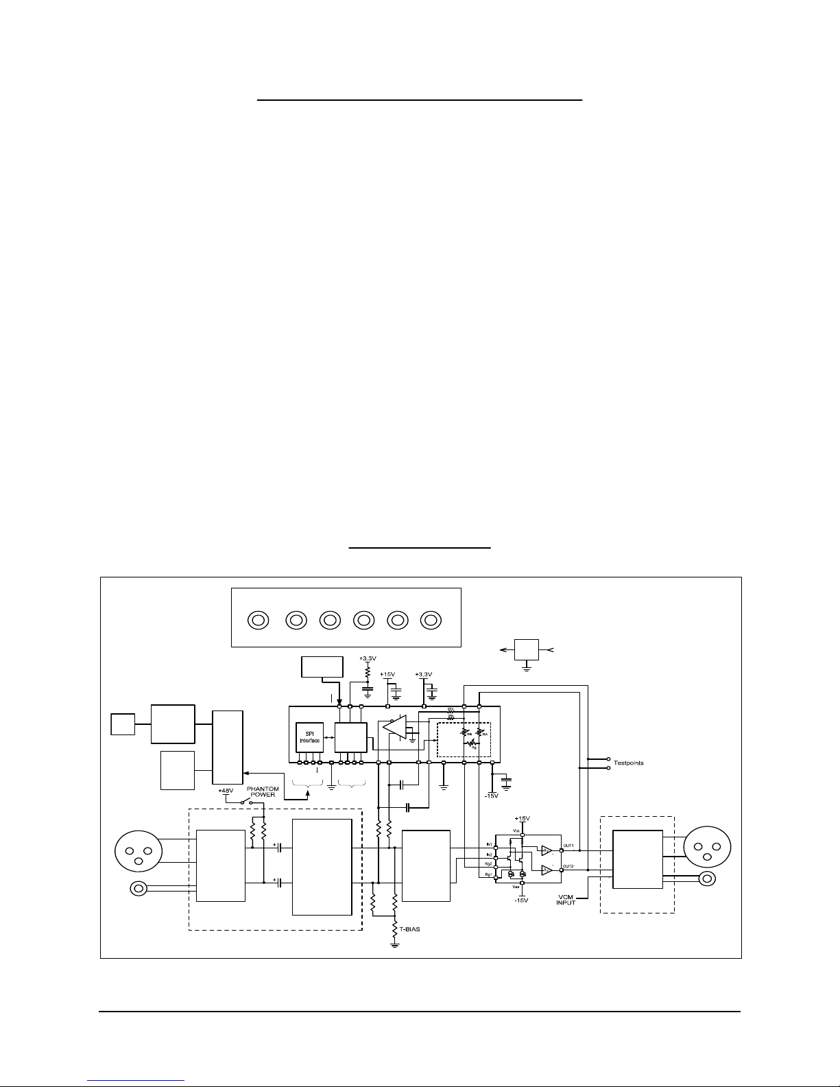
Block Diagram
Document 600134 Rev 02 Page 4 of 16 THAT 1570/5171-DEMO User’s Guide
THAT Corporation; 45 Sumner Street; Milford, MA 01757-1656; US
A
Tel: +1 508 478 9200; Fax: +1 508 478 0990; Web: www.thatcorp.com
Copyright © 2009, THAT Corporation; All rights reserved.
U2
THAT
1570
Servo
Rg1
Rg2
AGnd
DGnd
IN2
IN1
SCAP2
SCAP1
SOUT1
SOUT2
Resistor
Network
with FET
Switches
Control
Logic
SCLK
DIN
DOUT
CS
GPO1
GPO2
GPO3
GPO0
LEDs
RST
TRC
Vcc
Vcc
Vee
Vee
Vdd
BSY
U1
THAT
5171 --
+
+
Phantom
Power
Fault
Protection
RFI
Protection
RFI
Protection
USB
Interface
Ext
SPI
Conn
MUX
USB
SPI Bus
Reset
Switch
REG
+3.3V +5V
Mic/Line
Input
Balanced
Output
+48VCHAS +15 V -15V +5VGND
Power Supply Inputs
INPUT SECTION
Balanced
Output
Driver
OUTPUT
SECTION
Figure 1 -- Block Diagram of the THAT 1570/5171 Demo Board

Connections
Power
The USB interface runs on USB bus power, but the rest of the demo board
requires an external power supply. +/-15 V (maximum +/-17V) supplies the
analog circuitry. +48V phantom power is input (not generated on the board) and
switched on and off via the on-board Phantom Power switch. Note that the ground
return for +48V phantom power is via the CHAS (chassis ground) connector. The
+5V input is regulated on board to 3.3V and supplies the digital logic.
Audio Input
The Neutrik combo connector accepts an XLR or ¼” TRS cable. Maximum input
signal level is +21dBu with +/-15V supplies, or +22dBu with +/-17V supplies.
The 1/4” TRS signal path includes a 20dB pad in order to support very high line
levels.
Audio Output
Separate XLR and ¼” TRS connectors are wired in parallel. Maximum output
signal level is +21dBu with +/-15V supplies, or +22dBu with +/-17V supplies.
The differential attenuator/output buffer (U3) adds a small amount of noise and
distortion to the signal and it is therefore recommended that test points TP1-TP3
be used to measure performance of the 1570/5171 ICs.
USB
A PC must be plugged into the demo board via USB in order to control parame-
ters in the 5171 (e.g. gain). Take care not to hot plug the demo board while the
GUI software is running as this will often crash the Windows drivers.
General Purpose Outputs (GPO)
The GPO3:0 pins are connected to header J12. J12 is conveniently located near
the prototyping area, so the user can easily connect optional circuitry to them.
Note that the GPO pins are also connected to LEDs, D1-D4, and pull up and pull
down resistors which set the 5171 device address during reset. Consideration
must be given to how any application circuitry that is added interacts with these
other functions.
Hardware Set-up
1. Connect a power supply to the V+, V-, +5V, +48V, CHAS and GND
connectors. Do not turn on power yet.
2. Plug in the audio input and output
3. Attach a USB cable to the demo board, but do not plug it into the PC yet
4. Turn on the power supply
5. Turn on phantom power to microphone (if appropriate)
6. Plug USB cable into PC. Windows should go through its procedure for discov-
ering the new USB peripheral and loading its driver.
Document 600134 Rev 02 Page 5 of 16 THAT 1570/5171-DEMO User’s Guide
THAT Corporation; 45 Sumner Street; Milford, MA 01757-1656; US
A
Tel: +1 508 478 9200; Fax: +1 508 478 0990; Web: www.thatcorp.com
Copyright © 2009, THAT Corporation; All rights reserved.

7. Once the Windows driver has been loaded, launch the THAT Corporation
MicPreController GUI application. See software section (below) for further
instructions on operating the GUI.
8. When finished, close the MicPreController GUI first, then power down the
demo board. Unplugging the USB cable before the demo board is powered
down will likely crash the Windows drivers.
Software Set-up
Installation
1. Copy the files from the supplied Software CD into a folder on your PC hard
drive.
Document 600134 Rev 02 Page 6 of 16 THAT 1570/5171-DEMO User’s Guide
THAT Corporation; 45 Sumner Street; Milford, MA 01757-1656; US
A
Tel: +1 508 478 9200; Fax: +1 508 478 0990; Web: www.thatcorp.com
Copyright © 2009, THAT Corporation; All rights reserved.
Figure 2. Control GUI

2. Run the software installer pro
g
ram (double-click
"1570_5171_Demo_Setup.msi"). The installer automatically detects your
operating system and configures the appropriate drivers without any further
input from you. You will see a "DOS box" and Windows dialogue box temporar-
ily appear and then disappear during the process. Once the software installa-
tion process is complete, you will find an icon labeled "THAT 1570 5171 Demo"
on your desktop and a new THAT Corporation group in your start menu.
Operation
1. Apply power to the demo board, then plug the demo board into the PC via USB.
2. Launch the MicPreController GUI application.
3. The USB interface on the demo board will appear in Windows as a new COM
port. Click the COM drop down menu in the MicPreController application
and select the COM port associated with the USB module.
4. The GUI should now be connected to the demo board and ready to control its
parameters. The GUI initially turns on LED1 as an indication that it is
successfully communicating with the demo board. If LED1 is not lit, confirm
proper cable connections and that you selected the correct COM port in the
previous step.
5. Select “Immediate Update” or “Update on Zero Crossings” via the Gain Mode
drop down box, depending on your preference.
6. Move the gain slider to adjust gain of the 5171. Gains are continuously
adjusted as you move the slider. Note that gain settings of 1-7dB are invalid.
You may also adjust the gain slider by first giving it scope (clicking it with the
mouse) and then pressing the UP and DOWN arrow keys on your computer
keyboard, or by clicking the up or down arrow buttons next to the numeric
gain text box below the gain slider. The Step Size box in the Options area
allows you to set how many decibels the slider changes when you press the
UP/DOWN and arrow keys.
Jumper Options
T-Bias Jumper, J4
The input circuit provides a jumper (J4) which enables/disables the “T-Bias”
function. With a shunt intalled on J4, T-Bias is disabled and the circuit provides
a 2 kΩdiferential input impedance to the XLR input. With the shunt removed
from J4, T-Bias is enabled and provides a high common mode impedance (ideal
for both mic and line inputs) but maintains a modest differential impedance.
VCM Jumper/Input, J6
The output attenuator (U3) is normally biased at 0 VDC via R30 connected to
ground through a shunt on jumper J6. If the J6 shunt is removed, a bias voltage
may be input via J6, e.g. the common mode voltage output pin (VCOM) of an A/D
Converter.
Document 600134 Rev 02 Page 7 of 16 THAT 1570/5171-DEMO User’s Guide
THAT Corporation; 45 Sumner Street; Milford, MA 01757-1656; US
A
Tel: +1 508 478 9200; Fax: +1 508 478 0990; Web: www.thatcorp.com
Copyright © 2009, THAT Corporation; All rights reserved.

External SPI Host Jumpers & Connectors
The demo board has two connectors, J8 and J10, for connecting up to 8 boards
to an external SPI master device, such as a microcontroller. J8 is not installed at
the factory and it is up to the user to add it if required. Note also that current
limiting resistors R34, R36, R40, and R41 must be installed with the appropriate
value for the application. Please contact THAT Corporation technical support for
assistance.
Document 600134 Rev 02 Page 8 of 16 THAT 1570/5171-DEMO User’s Guide
THAT Corporation; 45 Sumner Street; Milford, MA 01757-1656; US
A
Tel: +1 508 478 9200; Fax: +1 508 478 0990; Web: www.thatcorp.com
Copyright © 2009, THAT Corporation; All rights reserved.
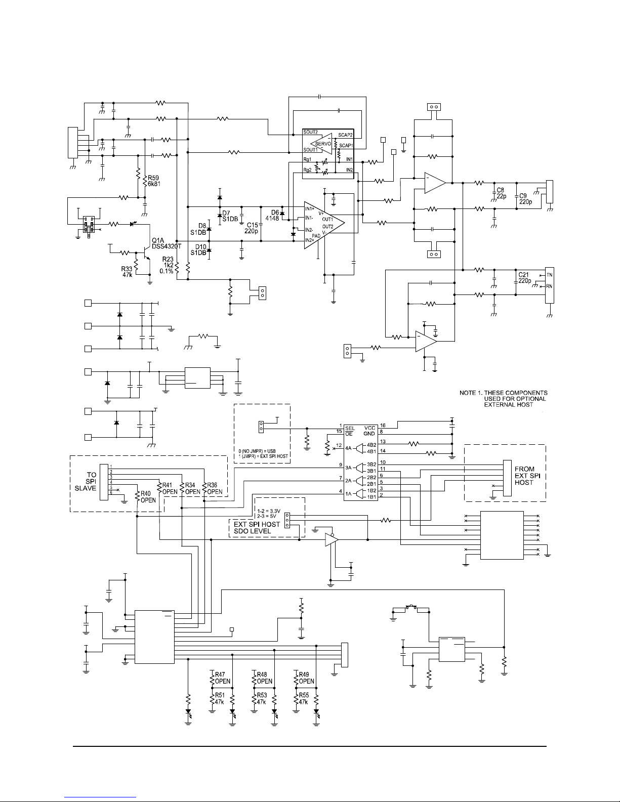
A
ppendix A. Schematic Diagram
Document 600134 Rev 02 Page 9 of 16 THAT 1570/5171-DEMO User’s Guide
THAT Corporation; 45 Sumner Street; Milford, MA 01757-1656; US
A
Tel: +1 508 478 9200; Fax: +1 508 478 0990; Web: www.thatcorp.com
Copyright © 2009, THAT Corporation; All rights reserved.
+48V
+48V
VA+
VA+
VA-
VA-
VA+
VA-
VA-
VA+
INPUT
PHANTOM
POWER
OUTPUT
close to chip
49R9
R4
C24
22p
R9
2k15
J2
11
22
33
G
4
T5
S6
R7
SW1
1
2
3
4
5
6C11
100p
C17
22p
D5
S1DB
+
+
+
THAT5171
U2A
32
31
3
6
30
29
4
5
TP3
J18
OPEN
R24
1k2
0.1%
1M2
R1
C19
22p
C25
100n
TP1
C1
22u NP
C3
22p
C7
100n
C2
22u NP
C14
22p
R16
10
R2
1M2
C22
100p
R3
49R9 R11
49R9
R7
1k13
R13
49R9
R18
49R9
R20
49R9
R29
VA-
4k99
R28
10k
R26
49R9
U3B
2114
7
6
5
+
U3A
2114
1
8
4
2
3
VA+
R30
2k49 C28
100n
C29
100n
U1
1570
2
3
6
7
10 17 12
13
15
C13
22p
+C27
47u
+
D11
RED
C23
100n
TP2
R12
2k15
J1
2
1
2
1
3
G
2k7
R31
1M2
R32
D9
4148
R10
10
C12
220p
C6
22p C10
47u
C16
47u
C5
22p
R8
9k09
R6
9k09
C4
220p
J3
R
2
S
1T
3
G
6
4
5
R42
6k81
C26
22p
R27
4k99
J19
OPEN
C18
22p
R15
1k13
21
T-BIAS
ENABLE
J4
2
1
VCM
INPUT
J6
2
1
USB_CS
USB_SCK
USB_SDI
SPI_SCK
SPI_SDI
SPI_SDO
SPI_CS
USB_SDO
3V3
3V3
+5V
USB
CONTROLLER
SPI HOST
SELECT R38
10K R39
10K
J11
DLP-232PC
CH3 1
CH4 2
CH5 3
CH2 4
CH1 5
CH9 6
GND 7
CH10 8
PORTVCC 9
GND
10 CH11
11 CH12
12 CH13
13 CH14
14 CH8
15 CH7
16 CH6
17 MCLR
18
GND VCC
74AHCT1G125
U8
1
24
35
J8
EXT_SCK
SEE NOTE 1
SEE NOTE 1
SEE NOTE 1
SEE NOTE 1
EXT_SDI
EXT_SDO
EXT_CS
J10
1
2
3
4
5
6
R58
0R
J22
1
2
3
J9 1
2
R37
10k
SN74CB3T3257
U5
R35
10k
C45
100n
C30
100n
3V3
3V3
3V3
VA+
VA-
RESET
R44
10k
R43
22M
R45
10k
C34
100n
R52
330
3V3
R50
330
SW2
12
34
R46
10k
C33
1n U6
ADM706SARZ
MR
1VCC
2GND
3PFI
4PFO 5
WDI 6
RST 7
WDO 8
D3
Red
D4
Red
U2B
THAT5171
VDD
13 VDD
21
DGND
12 DGND
20
VA+
9
AGND
10 AGND
28
VA-
11
CS 16
RST 15
SCK 17
SDI 18
SDO 19
BSY 22
TRC 14
GPO0 23
GPO1 24
GPO2 25
GPO3 26
C32
100n
C35
100n
C31
100n
GPO
J12
1
2
3
4
5
R54
330
3V3
D2
Red
R56
330
3V3
D1
Red
VA+
VA-
+5V
+48V
3V3
BLK
V-
RED
V+
GRN
GND
BLU
+5V
YLW
+48V
GRN
PHANTOM GND
D14
S1DB
C38
100n
C40
10u
J13
+C44
22u
+
J17
D13
S1DB
J14
D15
S1DB
J15
+C37
22u
+
C43
100n
+C42
22u
+
+C39
22u
+
D12
S1DB
J16
C41
100n
J20
TP5
R57
0R
U7
MAX604
IN
1GND
2GND
3OFF
4SET 5
GND 6
GND 7
OUT 8
C36
100n

Appendix B. Bill of Materials
DSS4320T-7Diodes, IncNPN, 20V, 2ADSS4320TQ1130
22-28-4363MolexConn., HEADER 36POS .100
VERT GOLD
CON3J22129
3760-4PomonaConn., 5-way binding post,
Yellow
5WBP, YLWJ17128
3760-6PomonaConn., 5-way binding post, Blue5WBP, BLUJ16126
3760-0PomonaConn., 5-way binding post,
Black
5WBP, BLKJ15125
3760-5PomonaConn., 5-way binding post,
Green
5WBP, GRNJ14, J20224
3760-2PomonaConn., 5-way binding post, Red5WBP, REDJ13123
22-28-4363MolexConn., HEADER 36POS .100
VERT GOLD
CON5J12122
DLP-232PCDLPPCB, USB ModuleDLP-232PCJ11121
22-28-4363MolexConn., HEADER 36POS .100
VERT GOLD
CON6J10120
OPENMolexConn., HEADER 36POS .100
VERT GOLD
CON6J8119
382811-6TYCOConn, shunt, 2-pos, 100milSHUNT-2POSJ5, J7, J21318
22-28-4363MolexConn., HEADER 36POS .100
VERT GOLD
CON2J4, J6, J9317
NRJ6HF-1Neutrik
Conn., Phone Jack, TRSNRJ6HF-1J3116
NCJ6FI-HNeutrikConn., Combo, PCBNCJ6FI-HJ2115
NC3MAHNeutrikConn., XLR, Male, PCBNC3MAHJ1114
CDSU4148ComchipDiode, DIODE SWITCHING
75V 150MA
4148D6, D9213
S1DB-13Diodes, IncDiode, RECTIFIER GPP SMD
200V 1A
S1DBD5, D7, D8, D10,
D12, D13, D14,
D15
812
SLA-560LT3FRohmLED, red, T1REDD1, D2, D3, D4,
D11
511
EEV-TG1J220PPanasonicCap, EL, 20%, 63V, 1ohm22uFC44110
ECJ-2FB1A106KPanasonicCap., 10V,10%, X5R10uFC4019
EEV-FC1E220PPanasonicCap. EL, 20%, 25V22uFC37, C39, C4238
ECJ-2VB1H102KPanasonicCap., 50V,10%, X7R1nFC3317
ECJ-2YB1H104KPanasonicCap., 50V, 5%, NPO100PFC11, C2226
EEV-TG1J470PPanasonicCap, EL, 20%, 63V, 1ohm47UFC10, C16, C2735
ECJ-2YB1H104KPanasonicCap., 50V,10%, X7R100nFC7, C23, C25,
C28, C29, C30,
C31, C32, C34,
C35, C36, C38,
C41, C43, C45
154
ECJ-2VC1H221JPanasonicCap., 50V, 5%, NPO220pFC4, C9, C12,
C15, C21
5
3
ECJ-2VC1H220JPanasonicCap., 50V, 5%, NPO22pFC3, C5, C6, C8,
C13, C14, C17,
C18, C19, C24,
C26
112
UWP1C220MCL1GBNichiconCap. EL, nonpol, 20%, 16V22uF/NPC1, C221
MFR PNMFRDescriptionValueRefQtyItem
Document 600134 Rev 02 Page 10 of 16 THAT 1570/5171-DEMO User’s Guide
THAT Corporation; 45 Sumner Street; Milford, MA 01757-1656; US
A
Tel: +1 508 478 9200; Fax: +1 508 478 0990; Web: www.thatcorp.com
Copyright © 2009, THAT Corporation; All rights reserved.

SN74AHCT1G125DCKTIIC, buffer, single74AHCT1G125U8158
MAX604CSAMaximIC, Adj LDO Reg.MAX604U7157
ADM706SARZAnalog
Devices
IC, Reset monitorADM706SARZU6156
SN74CB3T3257PWRTIIC, Quad MUXSN74CB3T3257U5155
NJM2114MNJRIC, op amp, dualNJM2114U3154
THAT5171THAT CorpIC, Mic Pre ControllerTHAT5171U2153
THAT1570THAT CorpIC, Mic PreTHAT1570U1152
1250KeystoneConn., Test pointTPTP1, TP2, TP3351
EVQ-PHV03TPanasonicSW., push, mom, DPSTSW MOM.
PUSH
SW2150
PBH2UEENAGXE SwitchSW., push, DPDTPBH2UEENAGXSW1149
RC0805JR-070RLYAGEORes., thick film,1/8W, 5%0RR57, R58248
RC0805FR-07330RLYAGEORes., thick film, 1/8W, 1%330R50, R52, R54,
R56
447
ERJ-6GEYK226VPanasonicRes., thick film, 1/8W, 10%22MR43146
RC55LF-D-6K81-B-BIRCRes., metal film, 1/4W, 0.1%6K81R42, R59245
RR1220P-103-DYAGEORes., thin film,1/10W, 25ppm,
0.5%
10KR35, R37, R38,
R39, R44, R45,
R46
744
RC0805FR-0747KLYAGEORes., thick film, 1/8W, 1%47KR33, R51, R53,
R55
443
RC1206JR-072K7LYAGEORes., thick film,1/4W, 5%2K7R31142
RR1220P-2491-D-MSusumuRes., thin film, 1/10W, 0.5%2K49R30141
RR1220P-103-DSusumuRes., thin film,1/10W, 25ppm,
0.5%
10KR28140
RR1220P-4991-D-MSusumuRes., thin film, 1/10W, 0.5%4K99R27, R29239
RGH2012-2E-P-122-BSusumuRes., thin film ,1/4W, 0.1%,
5ppm/c
1K2R24138
RGH2012-2E-P-122-BSusumuRes., thin film ,1/4W, 0.1%,
25ppm/c
1K2R23137
CMF5010R000FHEBVishayRes., metal film, 1/4W, 1%10R10, R16236
RR1220P-2151-D-MSusumuRes., thin film, 1/10W, 0.5%2K15R9, R12235
RR1220P-1131-D-MSusumuRes., thin film, 1/10W, 0.5%1K13R7, R15234
RG2012P-9091-B-T5SusumuRes., thin film ,1/8W, 0.1%,
25ppm/c
9K09R6, R8233
TNPW120649R9BEENVishayRes., thin film, 1/4W, 0.1%49R9R3, R4, R11,
R13, R18, R20,
R25, R26
832
RC0805FR-071M2LYAGEO
Res., thick film, 1/8W, 1%1M2R1, R2, R32331
Document 600134 Rev 02 Page 11 of 16 THAT 1570/5171-DEMO User’s Guide
THAT Corporation; 45 Sumner Street; Milford, MA 01757-1656; US
A
Tel: +1 508 478 9200; Fax: +1 508 478 0990; Web: www.thatcorp.com
Copyright © 2009, THAT Corporation; All rights reserved.
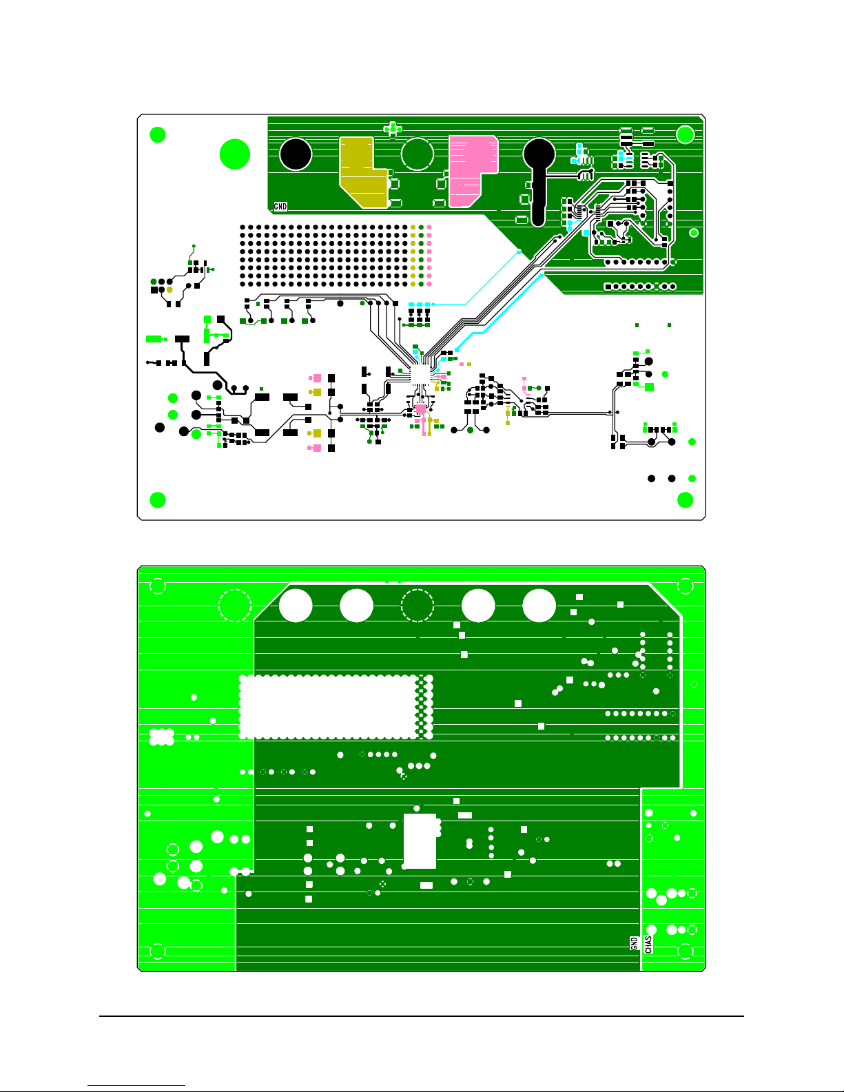
Appendix C. PCB Layout
Document 600134 Rev 02 Page 12 of 16 THAT 1570/5171-DEMO User’s Guide
THAT Corporation; 45 Sumner Street; Milford, MA 01757-1656; US
A
Tel: +1 508 478 9200; Fax: +1 508 478 0990; Web: www.thatcorp.com
Copyright © 2009, THAT Corporation; All rights reserved.
PCB Layout - Layer 2
PCB Layout - Layer 1 (Top)

A
ppendix C. PCB Layout (Continued)
Document 600134 Rev 02 Page 13 of 16 THAT 1570/5171-DEMO User’s Guide
THAT Corporation; 45 Sumner Street; Milford, MA 01757-1656; US
A
Tel: +1 508 478 9200; Fax: +1 508 478 0990; Web: www.thatcorp.com
Copyright © 2009, THAT Corporation; All rights reserved.
PCB Layout - Layer 3
PCB Layout - Layer 4 (Bottom)

Appendix C. PCB Layout (Continued)
Document 600134 Rev 02 Page 14 of 16 THAT 1570/5171-DEMO User’s Guide
THAT Corporation; 45 Sumner Street; Milford, MA 01757-1656; US
A
Tel: +1 508 478 9200; Fax: +1 508 478 0990; Web: www.thatcorp.com
Copyright © 2009, THAT Corporation; All rights reserved.
PCB Layout - Silk Screen

Notes
Document 600134 Rev 02 Page 15 of 16 THAT 1570/5171-DEMO User’s Guide
THAT Corporation; 45 Sumner Street; Milford, MA 01757-1656; US
A
Tel: +1 508 478 9200; Fax: +1 508 478 0990; Web: www.thatcorp.com
Copyright © 2009, THAT Corporation; All rights reserved.

Document 600134 Rev 02 Page 16 of 16 THAT 1570/5171-DEMO User’s Guide
THAT Corporation; 45 Sumner Street; Milford, MA 01757-1656; US
A
Tel: +1 508 478 9200; Fax: +1 508 478 0990; Web: www.thatcorp.com
Copyright © 2009, THAT Corporation; All rights reserved.
Revision History
9Corrected 5171 pin names on schematic diagramAugust 2011258902
6 - 7Change to software install procedur
e
December 2009236001
—
ReleasedNovember 2009—00
PageChangesDateECORevision
This manual suits for next models
1
Table of contents


