The Fisher Gusfom Electro lll User manual

ffi$Kffiffih$*l#r*l$ffiS'$ffi$
ffiffiffiffiffiisffiffiffiffi
CUSTOM
ETECTRAItr
dt^^pn*tu
HIGH FIDELITY
RADIO.PHONOGR,APH
MODEL
44O
ffi
ffi
ffi
ffi
ffi
"ffi
ffidff*$
ffi#sffi
ffis*ffis
,ffi.WW
ffiffi
ffiffi$
ffiss
*.ti
#ffi#trffiffiffieffi
#,i
ffiffiffitffil#ffi
,$
*$,*
i.ffi
,*1
ffi
#-ffi
ffi
,$
ffi
ffi
s
ffi
.ffi
ffi
ffi
ruit
iffiffi
t1,**
Esi!!
ffi!
{sf
ffi
qi*s
ffiiffi
ffiffi
$ffi$#
ffiffi
ffiffi
ffi#ffi ffi
ffiffiffiffi
ffissffi
ffiffiffi
AVERY FISHER
Founder
aail President,
Fither Radio Cor
porotion
The
McrnBehind
the Produet
/-\vER 20
vEARSAGo,Avery Fisher introduced America's first high fidelity radio-
L/ phonograph. That instrument attained instant recognition asheralding a new
era in the enjoyment of reproduced music. A number of the featuresof that early high
fidelity radio-phonograph were so basic that they are used to this day in all high
fidelity equipment. The engineering achievements
of Avery Fisher and the world-wide
reputation of his products have been the srrbject
of articles in Fortune, Tinte, Pugeant,
The New York Times, coronet, Lile, High Fidelity, Esquire, and other publications.
Benefit concerts for the National Symphony Orchestra in Washington and the Phila-
delphia Orchestra, demonstrating the great advances in reproducing equipment' used
FISHER instruments to play back the recordings that had just been made in the
presenceof the audience. "Fascinating evening, acoustically and musically," was the
Philadelphia Inquirer's comment, "the reproduction had remarkable fldelity." Ttue
magazinestated,
"Listenerscould hardly teil the differencebetween
real and electronic."
The FISHER instrument you have just purchasedhas been designed
to give you many
years of pride and enjoyment. It is the product of a company dedicated to bringing
reproduced music in its finestform, to the homesof America. If at any time you should
desire information or assistance
regarding the performance of your FISHER instru-
ment, please
do not hesitateto write direc1lyto Avery Fisher, President,Fisher Radio
Corporation, Long Island City 1, New Ycrk. Your communications will be welcome'
FISHER 'FIRSTS' - Milestones In Audio History '''
1937
Eirsthigh tidelity sound
systems
featuring
a
beam-oower
amplifier,
inverse
feedbacl('
acous'
tic ip'eaker
compartments
(infinitebaffle and
bass'rellex)
and
maSnetic
cartridges.
f93t Firstexclusivelv
high
fidelity
TRFtuner,
featuring
broad-tunins
20,000
cvcle
fidelity.
1937First
twcunit high
tidelity
system
withsoparate
speaherenclosure.
193! First
coaxial
spealer
system.
1930
First
highfidelity
tuner
withamplified
Avc.
1939
First
DynamicRange
Expander.
1939First
SWay
Spealer
in a highfidelity
system.
1939
First
Center-of-Channel
Tuning
Indicator.
t9it5 First
Preamplifier'
Equalizer
withselective
pho'
nograPh
equalization.
1948First
Dynamic
Range
Erpander
with
feedback.
1949
first FM-AM
Tuner
withvariableAFc.
1952
Firstso-Watt,
all-triode
amplifier.
1952First
self-powered
MastetAudio
Control.
1953
Firstself-powered,
electronic
sharp-cut'off
fil'
ter system
lor hiSh
{idelityuse'
195t First
Universal
Horn'Type
Speaker
Enclosure
for
anv
toom
location
and
anyspeaxer.
1953first FM-AM
Receiver
with
a Cascode
Front
End.
1954
Firstlow-cost
electronic
Mixel'Fader.
1954
Firstmoderately-priced,
prolessional
FM
Tuner
withTwometers.
1955First Peak
PowerIndicator
in hightidelity.
t955 FlrstMasterAudio
Control
Chassis
with tive-
position
mtxlng
lacilities.
1955
First
correctly
equatized,
direct
tape'head.m"s'
ter
audio
confrols
andseif4owered
preamplifier.
1956
Firstto lqcorporate
Power
Monitor
in a home
amplif
ier.
1956
first All-Transistorized
Preamplifier-Equalizer.
1956first dual
dynarnic
limiters
in an FMluner
for
homeuse.
1956First Performance
Monitor
In a hiShquality
amPlifier
for homeus€-
1956First
FM-AMtuner
withTWo
meters.
1955Firstcomplete
graphic
response
curve
indicator
for bass
andtreble.
1957
FirstGold
Cascode
FM
Tuner'
1957
First
MicroRay
Tuning
Indicator.
1958
First
Stereophonic
Radio-Phonograph
with
Mag'
neiic
SteIeo
Cartridge
1959
First
high-quality
Stereophonic
Remote
Control
SYstem.
1959
Firiicomplete
Stereophonic
FM'AM
Receiver
(FM-
AM
tuner,
audio
control,
4o'watt
amplifier).
THEFISHERGusfomElectrolll
Model 44O Srereo Rqdio-Phonogroph
INTRODUCTION
The Custom Electra I'II Moilel 440 is a complete radio-phono'graph
system
designedto play all stereophonic
and monophonic records and to receiveFM,
AM and FM-AM stereobroadcasts.
The unit consists
of a 610 receiverchassis,
a 30-A power amplifier chassis,
a four-speedrecord changer,and two matched
speakersystem
- all housedin an attractiveconsolecabinet.Input connections
are provided to play a tape recorder or other high-level sound sourcethrough
the Custom
Electrasystem.
No additional amplifiers or speakers
are required for
stereophonic
or monophonicsound reproduction.
THE FISHER Custom
ElectraIII system
is capableo[ providing more lhan
ample volume for all your needs
without di.stortion,and the easy-to-use
Stereo
Control Centerpermits the sound torbe adjusted to your personel tastes.THE
FISHER FM-AM receiver
is renowned
for its extreme
sensitivity,assuring
you of
high-fidelity reception even in extremefringe ar.eas.
Your phonograph records,
stereophonic
and monophonic,
are safely and properly reproduced
on the world-
famous Garrard four-speed automatic record player. To the Garrard, IISHER
has addeda stereophonic
cartridge equipped
with a d,iamorud,
LP stylus for long
recordlife and minimum record wear, with a flip-over stylusfor playing 78 rpm
discs.This cartridge is of the compatible type, which meansthat it will play
either stereoor monophonic recordings.
The ease
with which you can utilize the many wonderful features of THE
FISHER wil'l be readily apparentwhen you have read the concise,
yet complete,
instructions on the pagesthat follow.
STEREOPHONIC
SOUND
In monophonichigh fiilelity systems,
the reproducedsound has all the char-
acteristicsof the original performance- with two exceptions.Thesearedirection
and.
d,istance.
With the advent of stereophonic
high fidelity systems?
all the
characteristics
of live sound are now capableof being reproducedin the home
or auditorium. THE FISHER Model 440 constitutesa complete stereophonic
system. 1

Reproductionof the live sound characteristicsof direction and distanceare
made possible by the use of troo sound sources and two sound channels.for
example, two microphonesare placed before an orchestraso that they "hear"
the music as we would, with both ears.W'hat is picked up by eachmicrophone
is then recordedseparately
and independentlyon record or tape?
or broadcast
as a stereo
radio program. The stereo
program is then reproducedthrough two
separatesound channels.The soundoriginally picked up by the microphone on
the right is used
to drive a speaker
system
on your right, while the soundpicked
up by the microphone on the left simultaneouslydrives a speakersystem on
your left.
The effectivenessof stereophonicsoundin achieving realismis much greater
than might be imagined on the basis of the simple explanation just given. The
stereo
systemactually spreads
out the orchestral
soundin the samemanner as it
would emanate
from the stage.
In other word, instruments
locatedat centerstage
are heard at a point midway betweenthe speakers.
The other orchestralinstru-
ments can be locatedaccordingly from left to right. This resultsin a realism
and clarity never before possiblein high fidelity systems.
Stereophonic
soundprograms are now available on phonographrecordsand
magnetictapesand may also be heard on three types of stereobroadcasts:FM-
AM, FM-FM and FM multiplex. The CustomElectra has been designed
to permit
you to listen to all of thesestereosourcesas well as to standard monophonic
prograrns.
INSTATTATION
THE FISHER operateson AC only. The AC Power Cord at the back of the
instrument must be connected
to a line receptacle
supplying I05 to 120 volts at
60 cycles.A step-up transformer can be used where the line voltage is lower,
a step-down
transformer where it is higher. THE FISHER can be modified for
S0-cycleoperation by means of an adaptor for the record changer, which is
available from your Fisher dealer. Total power consumption is 245 watts. A
2-ampereSlo-Blo fuse is usedto safeguardthe 610 chassis
and a l-ampere Slo-
Blo fuse protects the A-30 chassis.Neuer insert a twse ot' rating ,lfigher than
specified,,
or seoere
d,amagemay resuh.
record chqnger...
Be sure that the shipping screws designated
by red and white tags have been removed'
This is normally done when the instrument
is delivered and set up. Be sure that the pro-
tective cover on the underside of the phono-
graph cartridge has beenremoved,exposing the
stylus. If it has not, hold the pick-up arm
firmly and remove the cover guard with a
fingernail.
lilx'!,+@
AUXAC
RECEPTACTES
lr d
For 30.A Chossis
l...-l
l0 rl
For
Record
Chonger
\n
n) [ rusr
;
+r v1
.l 2 tl'l.p,
I SLO-B|OFUSE
si
tFl
HII
eo
qf;
7
rN*
TF
=z
rP
LNI
il
=Nf;
@o
I PHONO TUNER AUX I
;NpUTS-J OUTpUT
POWER
TRANSFORMER
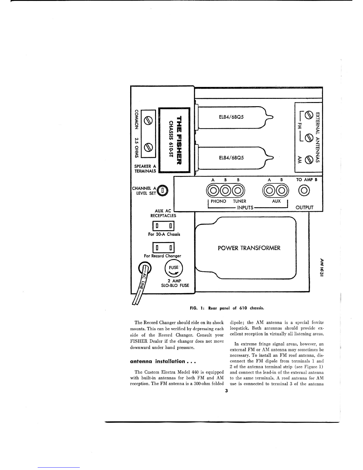
Reor ponel
The Record Changer should ride on its shock
mounts. This can be verified by depressing
each
side of the Record Changer. Consult your
FISHER Dealer if the changer doesnot move
downward under hand pressure.
dnfenncr instollction . . .
The Custom Electra Model 44Ois equipped
with built-in antennas for both FM and AM
reception. The FM antenna is a 300-ohm
folded
of 610 chqssis.
dipole; the AM antenna is a special {erlite
loopstick. Both antennas should provide ex-
cellent reception in virtually all listening areas.
In extreme Iringe signal areas, however, an
external FM or AM antenna may sometimes
be
necessary. To install an FM roo{ antenna, dis-
connect the FI\{ dipole from terminals I and
2 of the antenna terminal strip (see Figure 1)
and connect the lead-in of the external antenna
to the same terminals. A roof antenna for AM
use is connected to terminal 3 of the antenna

strip. The Ierrite loopstick need not be re-
moved.
Note! The FM section oI your receiver may
also be fed from your TV antenna by means of
a two-set coupler. See your Fisher dealer or
service man {or making this installation.
inputconneclions...
The FisherCustom
Electra
Model440 is
shipped from the factory with all components
properly connected to permit you to listen to
monophonic and stereophonic records as well
asto FM and AM radio broadcasts.
In addition,
connections are provided on the 610 chassis at
the rear o{ the cabinet as shown in Figure 1.
These are for plugging in an external tuner
for stereo broadcasts, as well as a tape recorder
or some other high-level program source. Auxil-
iary sound sources are connected as described
below.
PHONO INPUTS:
The Phono6A and B Inputs
are for connecting the record changer to the
610 chassis. These connections are made at the
factory so that the Channel A stereo component
is heard in the speakers on the left and the
Channel B portion in the speakers at the right.
If the leads {rom the record changer should be
disconnected for any reason, make sure they are
replaced as they were originally connected so
that the channels are not reversed.
TUNERINPUTS:
The Tuner B input is used to
connect an external tuner to the Custom Electra
system to provide the B channel o{ a stereo
broadcast. For FM-AM programs, connect an
AM (or FM-AM) tuner to the Tuner B Input.
For FM-FM broadcasls, an FM (or FM-AM)
tuner is plugged in.
The external tuner operates in conjunction
with the FM tuner section in the 600 receiver
to provide & stereo broadcast. The portion of
the program supplied by the 610 receiver is
heard in the speakers on the left; the portion
supplied by the external tuner is heard in the
right-hand speakers. The Tuner B Input may
also be used for making connections for an trM
multiplex adaptor, as described below.
AUX INPUTS:The auxiliary inputs are used
for connecting a tape recorder, a shortwave
tuner, or other high-level program source to the
Electra sound system, A stereo tape recorder
must be connected to both the AUX A and
AUX B inputs. A monophonic or other single-
HUMADJUSTMENTS
12
@@ z
U
x-x
d<o
=E=
AW 1632
FtG. 2: Top view of 6lO chqssis
showing hum odiustments
ond multiplex connection
brqcket.
4
channel sound sourceis connectedto the AUX
A input only. The auxiliary sound source,
whether stereo or monophonic, will be heard in
both speakers.
Note: The sound portion oI a TV broadcast
may also be connected to the Channel A Aux
Input. Cautionl This connection should be
made only by a qualified technician.
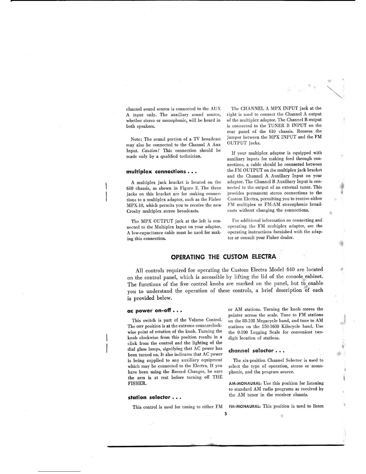
multiplex Gonnections
. . .
A multiplex jack bracket is located on the
610 chassis, as shown in Figure 2. The three
jacks on this bracket are lor making connec'
tions to a multipiex adaptor, such as the Fisher
MPX-10, which permits you to receive the new
Crosby multiplex stereo broadcasts.
The MPX OUTPUT jack at the left is con-
nected to the Multiplex Input on your adaptor.
A low-capacitance cable must be used for mak'
ine this connection.
The CIIANNEL A MPX INPUT jack at the
right is used to connect the Channel A output
oI the rnultiplex adaptor. The Channel B output
is connected to the TUNER B INPUT on the
rear panel oI the 610 chassis. Remove the
jumper between the MPX INPUT and the FM
OUTPUT jacks.
If your muitiplex adaptor is equipped with
auxiliary inputs for making feed through con'
nections, a cable should be connected between
the FM OUTPUT on the multiplex jack bracket
and the Channel A Auxiliary Input on your
adaptor, The Channel B Auxiliary Input is con-
nected to the.output of an external tuner. This
provides permanent stereo connections to the
Custom Electra, permitting you to feceive either
FNI multiplex or Fl\{-AM stereophonic broad-
casts without changing tlre,connections.
For additional information on connecting and
operating the FM multiplex adaptor, see the
operating instructions {urnished with the adap-
tor or consult your Fisher dealer.
f
OPERATING
THECUSTOM
ETECTRA
All controlsrequiredfor operatingthe Custom
ElectraModel 440 arelocated
on the control pu.r"l, *hi.h is accessible
by lifting the lid of the console-cabinet.
The functions of the five control knobs are marked on the panel, but to.enable
you to understandthe operation of thesecontrols, a brief descriptionbf each
is provided below.
qG Power on'ofr. . .
This switch is part of the Volume Control'
The orr position is at the extreme counterclock-
wise point of rotation of the knob. Turning the
knob clockwise from this position results in a
click Irom the control and the lighting of the
dial glass lamps, signifying that AC power has
been turned on. It also indicates that AC power
is being supplied to any auxiliary equipment
which may be connected to the Electra' If you
have been using the Record Changer, be sure
the arm is at rest before turning ofi THE
FISHER.
stqtion selector...
Thiscontrol
isused
for tuning
to either
FM
or AM stations. Turning the knob moves the
pointer across the scale. Tune to FM stations
on the BB-108
Megacycle band, and tune to AM
stations on the 550-1600Kilocycle band. Use
the 0-100 Logging Scale for convenient two'
digit location of stations.
Ghqnne!seiector. . .
The six-position Channel Selector is used to
select the type of operation, stereo or mono-
phonic, and the program source.
AM-MONAURAI: Use this position for ]istening
to standard AM radio programs as received by
the AM tuner in the receiver chassis.
FM-tvloNAURAL:
This position is used to listen
I
E
."i!
{.
:.$!
i
L
I
i
TREBLE
@
MIN MAX
BASS
/4.
N\ tt,
\v
MIN MAA
VOLUME
'@'
ON.OFF
RADro^rA PHoNo
':v:;^"
^ STEREO
. MONAURAT
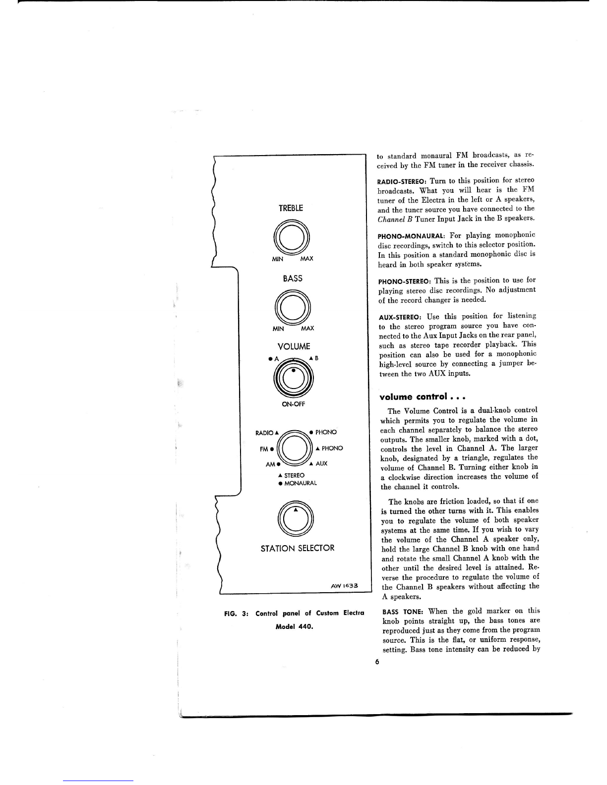
FlG. 3: Control Ponel of Custom Electro
llodel 440.
to standard monaural FM broadcasts' as re'
ceived by the FM tuner in the receiver chassis'
RADIO-STEREO:
Turn to this position for stereo
broadcasts. What you will hear is the FM
tuner of the Electra in the left or A speakers,
and the tuner source you have connected to the
Channel B Tuner Input Jack in the B speakers.
PHONO-MONAURAL:
For playing monophonic
disc recordings, switch to this selector position'
In this position a standard monophonic disc is
heard in both speaker sYstems.
PHONO-STEREO:
This is the position to use for
playing stereo disc recordings' No adjustment
oI the record changer is needed.
AUX-STEREO:
Use this position {or listening
to tbe stereo program Eource you have con'
nected to the Aux Input Jacks on the rear panel,
such as stereo tape recorder playback. This
position can also be used lor a monophonic
high-level source by connecting a jurnper be'
tween the two AUX inPuts.
volumecontrol
...
The Volume Control is a dual-knob control
which permits you to regulate the volume in
each channel separately to balance the stereo
outputs. The smaller knob, marked with a dot,
controls the level in Channel A. The larger
knob, designated by a triangle, regulates the
volume oI Channel B. Turning either knob in
a clockwise direction increases the volume o{
the channel it controls.
The knobs are friction loaded, so that if one
is turned the other turns with it. This enables
you to regulate the volume oI both speaker
systems at the same time. If you wish to vary
the volume of the Channel A speaker only,
hold the large Channel B knob with one hand
and rotate the small Channel A knob with the
other until the desired level is attained. Re-
verse the procedure to regulate the volume of
the Channel B speakers without afiecting the
A speakers.
BA55 IoNE: When the gold marker on this
knob points straight up' the bass tones are
reproduced just as they come from the program
source. This is the flat, or uniform response,
setting. Bass tone intensity can be reduced by
6
turning the control toryard the narxposition on
the le{t, while turning it toward the u.Lx posi
tion on the right increasesit. At high volume,
it is best not to use extreme clockwise settings
o{ this control, since distortion of sound may
occur.
TREBIE
TONE: When the gold marker on this
is pointing straight up, the treble tones are un-
afiected. For a more intimate tonal quality, turn
the control to the left (toward nrN) to the
desired degree.For a more brilliant tone, turn
the knob toward the rrex position on the right.
SERVICE
INFORMATION
There are four chassisadjustments
which have been set at thb factory to
provide the best listening results for your Custom Electra. These include two
Hum Adjustments on the receiverchassis(seeFig. 2) and a Channel A Level
Seton the rear panel (see
I'ig.1). The Channel
B Level Setis located
on the
small amplifier chassis.
The Hum Adjustments are used to suppress
hum in the speakers,and the
Level Sets provide a meansof balancing the speaker outputs for stereophonic
listening. Theseadjustments
should be made only after extensive
tube changes
or other servicing work have beenmade on the Custom Electra.
HUr\l
ADJUSTl: With no program being played,
turn the Volume Control to minimum. Turn
the Channel A Level Set on the rear panel to
maximum (clockwise). Turn the Channel B
Level Set on the amplifier chassis to maximurn
(fully clockise). Using a small, slot-head
screw-
driver, rotate Hum Adjust 1 for minimum hum
from the speakers.
HUM ADJUST
2: A{ter setting Hum Adjust 1,
turn the Volume Control to maximum. Using a
small slot-head screwdriver, set Hum Adjust 2
for minimum hum from the speakers.
IEVELSETS:
Turn the Channel A and Channel
B Level Sets to maximum position (Iully clock'
wise). Set the Volume Control on the front
panel so that both knobs are at mid-position.
Play a stereo record through the Electra and
note the relative level of the two speaker sys.
tems. I{ the speakers to your left sound notice'
ably louder, turn the Channel A Level Set down
until the two volumes are equal. Make a similar
adjustment of the Channel B Level set if the
right speaker system is appreciably louder than
the le{t.
Part
No.N770.101
Note! The Channel A Level Set. which con-
trols the output of the speakers on the left as
you face the Electra, is located on the receiver
chassismounted on the right sideo{ the cabinet.
The right speaker system is controlled by the
Level Set on the amplifier ohassis on the left
side of the console.
ql your service . . .
It is the constant desire oI Fisher Radio
Corporation to have your FISHER give you its
best possible performance. Toward that objec-
tive, we solicit your correspondence on any
special problems that may arise.
After you have
had an opportunity to {amiliarize yoursell with
THE FISHER, we would appreciate
your letting
us know how it is meeting your requirements,
your fisher deqler...
Be sure to consult your FISHER Dealer
promptly iI any situation arises that indicates
a possible defect. Your FISHER Dealer stands
ready to assist you at any time,
t
l
4
23IRF24C-79

t .'
o finol wotd . . .
Have this booklet handywhile you get acquainted
with your new FISHER, thenkeepit in a safe
place
asa valuable
reference
to which you can turn.
If anvquestion
arises
towhichyoucannot
find the
answer,-pllase
donot
hesitate
towriteus.
We'llbe
glad
tohearfiom you,andapromptreplywill follow.
'*.
.-t
,
Avenv FrsHER,
PRESIDENT
I
t a.j
,l
j
i
,tj
.:
,,,
.'.1
r:,:*'j
'',tl
." t.;.i
1
:' l.=A
A*v Ftt'r,
This manual suits for next models
1
Table of contents


