The global Selection 333SK User manual

The L
Selection
333SK
HIGH
SPEED
LOCKSTITCH
SEWING
MACHINE
WITH
EDGE
CUTTER
Service
manual
Parts
catalog
From the library of: Superior Sewing Machine & Supply LLC

ATTENTION:
To avoid wrong performance
of
sewing ntachine or potential damage
towards it , anake sure
of
the following items before operation:
0 Wipe
and
clean the machine before initial operation.
0 Oil
the
machine aftea· cleaning it.
0
The
voltage
is
correct.
0 Plug is pa·operly connected.
0 Running
under
impa·oper voltage
is
strictly foa·bidden.
0
Motor
pulley rotates in right direction.
1.
MAIN
SPECIFICATIONS
I)
Max
se\ving speed:
2) Stitch length:
3) Presser foot lift:
4) Needle bar stroke:
5)
Take-up lever stroke:
6) Knitc stroke: 5mm
7)
Needle:
8) Application:
9) Reverse teed device:
2.
MACHINE
INSTALLATION
4SOOrpm
0-Smm
Smm (by hand)
13mm (by knee)
31.8mm
58mm
DBxS #
14
light to medium heavy weight material
available
I) Put the rubber cushions to the tbur corners
of
the oil reservoir, then
set
the
oil
reservoir to the table.
2) Insert the hinge(}) to the hole tor the hinge on the machine head. then set
the
n1achine head onto the rubber cushions and the hinge
sockets®
on the table.
3) Align Motor Pully Groove (B) and Balance Wheel Groove (A)
by
moving
the
n1otor(C) let\ward or rightward.
1 .
From the library of: Superior Sewing Machine & Supply LLC
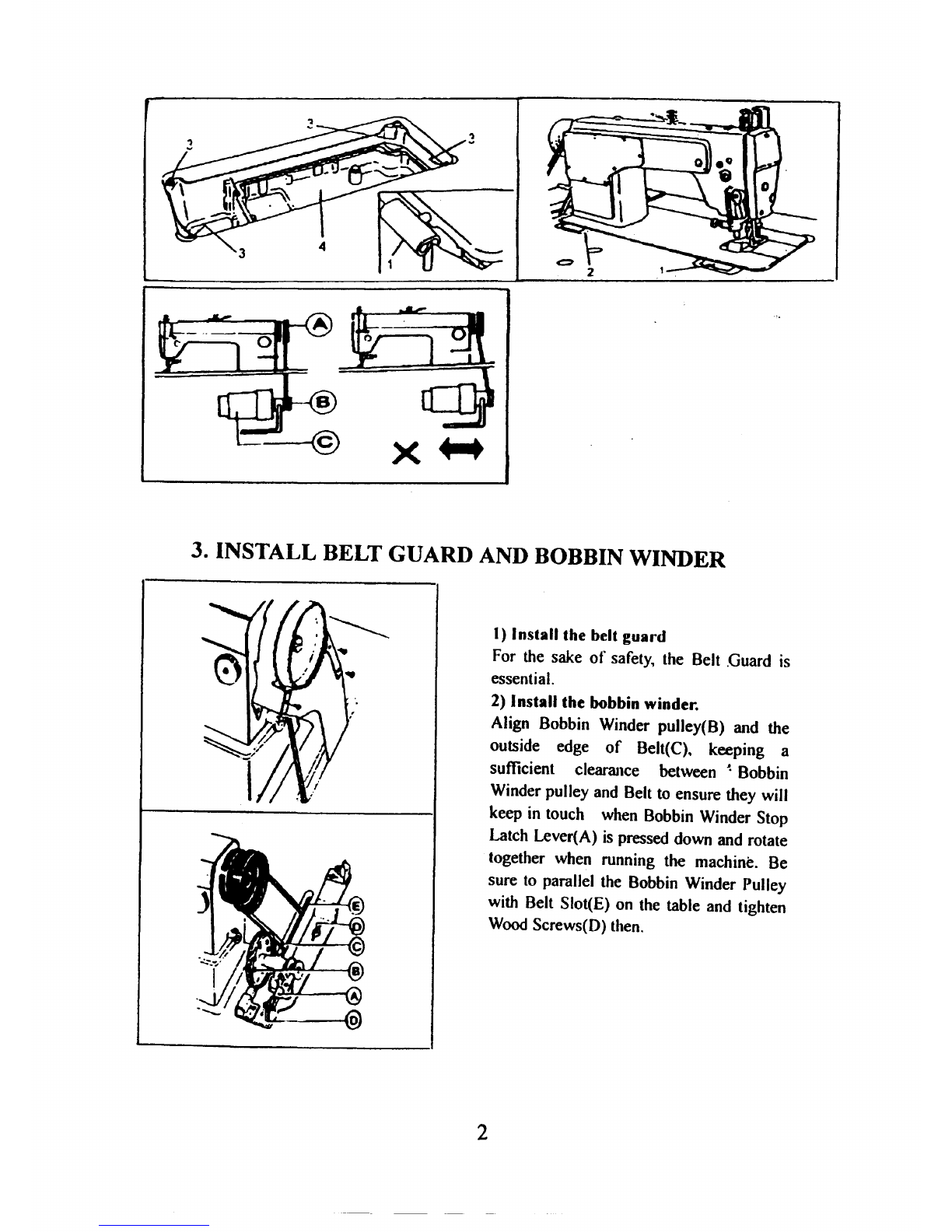
3. INSTALL BELT GUARD AND BOBBIN WINDER
2
I)
Install
the
belt
guard
For the sake
of
safety, the Belt .Guard is
essential.
2) Install
the
bobbin winder.
Align Bobbin Winder pulley(B) and the
outside edge
of
Belt(C).. keeping a
sufficient clearance between
~
Bobbin
Winder pulley and Belt to ensure they will
keep in touch when Bobbin Winder Stop
Latch Lever(A)
is
pressed down and rotate
together when running the n1achine. Be
sure to parallel the Bobbin Winder Pulley
with Belt Slot(E) on the table and tighten
Wood
Screws(D) then.
From the library of: Superior Sewing Machine & Supply LLC

4.
INSTALL
CHIP
RETAINING
PLATE
4
-€>
~-3
Install Chip Retaining
PlateQ) on Chip Funnel
Plate ® to completely
prevent chips
fro1n
getting
out. Then set the
.oil
guide
chute onto the oil
reservoir as following:
I) The forepart
of
the oil
guide chute n1ustn
't
stretch lettwards too
far
fro1n
the
lengthened line
of
Plane (A).
2) Part (B)
of
the chip
funnel
won't
touch the
oil guide chute when
turning up or down
the 1nachine head.
5.
CONNECl~
CLUTCH LEVER WITH PEDAL
X
I)
The optinuun tile angle
of
Pedal is approximately
15
deg.
2) Adjust Clutch Cover so ·that
Clutch-lever and Draw
bar
run
in line.
3) The balance wheel should
rotate counter-clock wise when
vie\ved
fro1n
the outside
of
Balance wheel. The direction
of
1notor pulley rotation can be
reversed by reversing (turning
over
180
deg) the power plug
of
the anotor.
4)
Adjust the tension
of
V-belt
by
moving the motor up and down. The proper tension
of
the
V-belt
is
a slack
of
I0-20mm when the belt
is
depressed at the center
of
the belt
by
tinger.
3
From the library of: Superior Sewing Machine & Supply LLC

6.01LING
I) Required amount
of
----------------------,
oil
I
,.
H L I
j~~
"-
Line
(H)
on
the
oil
reservoar:
Max.
oil
level
Line
(L)
on
the oil
reservoir:
Min.
oil level
If oil
level
goes down
under Line(
L)~
oi
I can
not
be
distributed
to
each part
of
the
machine. thus causing
the
parts a seizure.
2) AIways
use
18#
special
n1achine
oil
for
high
speed sewing machine
only.
Be
sure
to
replenish
oil
to
Line
(H)
before operation.
3)
To
replace oil, loosen Screw(C)
to
drain used
oil.
After completely draining on· oil, clean
the
oil
rt·servoir and securely tighten Screw(C), then
till
the
reservoir
with
fresh
oil.
7.
RUN-IN
OPERATION
..
--·:c··
,
______
, .
4
Run-in operation
is
required
for
a
new
sewing
anachine.
or a sewing
machine lell out
of
operation tor a
considerable length
of
time.
I)
Remove
Rubber Plugs(
A)
on
the
top
of
the ann
and
replenish sufticient
amount
of
oil.
2)
Lift Presser Foot(B)
3)
Run
the
machine
at
a
lo\v
speed
(2000-2500span) to check oil distributing
condition through
Oil
Check
Windo\v(C).
4
)Perton11
run-in operation
at
2000-2500spnl tor 30
aninutes.
Afler a
lapse
of
one
anonth
of
service during
which
the
working speed
is
increased
gradually, the machine
runs
sufficiently
well, and the high speed 4500spm can
be
adopted according to
the
nature
.of
the
work.
From the library of: Superior Sewing Machine & Supply LLC

8.
I{Ef>LACE NEELJLES
§
I.
I~~
t •
1!~
. a u
'·!-'"
1)
X
'
v'
b
I
'
~
c
I
,
/
a
1
Turning the balance
wheel to lift needle bar to the
upper end
of
its stroke.
Loosen Needle claaup Screw
(I).
While keeping the long
groove
of
the needle lethvard.
fully insert the needle shank
up
to
the bouoan
of
the
net=dle
socket. Then tighten Needle
clamp Screw
(I
).Note:
Fig.(
b)
insufficient insertion.
Fig.(c) wrong direction
of
long groove.
9.
ADJUSl
..
PRESSURE AND HEIGHT OF PRESSER FOOT
5 .
I) l)ressua·c
adjusllnent:
Pressure
of
presser
ft)(lt
as
to he adjusted according, to
the
thil:kncss
or
materials
to
be
sewn.
Loosen Lock Nut
(A)
ti
rst.
for
heavy anaterials.
tun1
the
pressure regulating
thuanb
screw
as
shown
in
Fig.
(a) to
increase the pressure. while
tor light anaterials.
tun1
the
pressure regulating thumb
screw
as
shown
in
Fig.
(b) to
decrease the pressure. Then
tighten I.ock Nut
(A).
2)
llcigbt
adjushncnt:
I)
Ren1ove
Rubber plug
(C)
troan
Face plate (B).
2)
Loosen scre\v o
t:
presser
bar guide
bra<.:ket
and
adjust the height
of
Presser
Bar.
3) Tighten screw again and
put
in
Rubber Plug(
C).
From the library of: Superior Sewing Machine & Supply LLC

I
0.
THREADING
11.
ADJUST THREAD TENSION
6
I) To thread the needle
thread. raise needle bar to
the upper end
of
its stroke,
lead the thread from spool
and perform threading as
per threading sequence.
2) To draw the bobbin thread.
hold the end
of
the needle
thread and turn the balance
wheel to lower the needle bar
and then to lift
it
to its highest
position. Pull the needle
thread and the bobbin thread
is
drawn
up.
Put the ends
of
needle thread and bobbin
thread frontward under
presser foot.
I)
To
adjust bobbin thread
tension. turn Tension
Spring Regulating Screw
(A)
of
Dobbin case
clockwise f(n more
tension, or turn the screw
counter -clockwise for
less tension.
2) The needle thread tension
should be adjusted with
reference to the bobbin
thread tension and it can
be
adjusted by setting the
thread take-up spring
tension~
the thread take-up
spring stroke and the
position
of
thread tension
discs
or
thread guide.
From the library of: Superior Sewing Machine & Supply LLC

12.
INSTALLATION
AND
OPERATION
OF
THE KNIFE
Knife operation:
(I)
To
actuate the cutting knife
..
press
down Knife operating plate (
1)
to
lo\ver the knife while running the
sewing machine.
II"'Cn'--+ (2)
To
stop cutting
of
the knife tor
7
sewing only. pull out Knob(2) as
indicated
by
the arrow.
Knife installation:
Install the cutting knife
as
shown in the
tigure. When bringing the knife to the
lowest position. move it up and down to
make sure the part A
of
the knite
is
0-0.Smm lower than the surface
of
the
needle plate.
Cutting
width change:
(I)
The cutting width can be varied
by
changing needle plate assy. When
changing, loosen Set Screw(I) and
pull out cutting knife parallely to
ensure a good cutting quality.
(2) Due to the change
in
the size
of
needle plate assy. you nuast change
the position
of
the cutting knife
accordingly. Loosen Screw(2) to
anake
the edge
of
cutting knife touch
the edge
of
needle plate assy, then
tighten the screw·again.
(3) 3.2mm is the standard
specification
of
this needle plate
assy.
From the library of: Superior Sewing Machine & Supply LLC

13.
ADJUST TENSION
OF
NEEDLE & BOBBIN
THREAD
l.
•
•
a
b
c
d
e
The position
of
the thread guide
affects stitch tightness and theref(lre
must be adjusted according to sewing
material and sewing conditions. Fig.
(a)
sho\vs the correct stitch.
Abnormal sti.tches cause puckering
and thread breakage.
In
such a case
the tension
of
needle thread and
bobbin thread must be adjusted
accordingly.
I)
In
case
of
needle thread tension
is
too
strong
or
bobbin thread tension
is
too weak. turn the thumb nut
counterclockwise to decrease the
needle thread tension.
or
tighten the
tension spring regulating screw
of
bohhin case to increase the bobbin
thread tension.
2)
In
case
of
needle thread tension
is
too weak
or
bobbin thread tension
is
too strong. turn the thumb nut
clockwise to increase the needle
thread tension.
or
loosen the tension
spring
regul«;~ting
screw
of
bobbin
case to decrease the bobbin thread
tension.
3)
In
case
of
the stitch f(lrnls
of'·d
.. and
'"e"·.
adjustments can be made with reference
to
the ahove rneans.
14.
REPLACE
OT~1ER
PARTS
I)
When not usmg the cutting
kni
fc.
place the cover onto the
opening A
of
the chip tunnel.
2) Atter putting on the cover. the
machine can
sew
only.
u
8
From the library of: Superior Sewing Machine & Supply LLC

15.
I{ELAI'ED
PARI'S FOI{ CI-IANGINU CU'J"J'INU
WILJI'I
I
~NAME.-
..--------
..
--r-··
----,
------
~
NEEDLE
FEED
PRESSER
KNIFE
CHIP CHIP I CHIP
FUNNEL
PLATE
DOG
FOOT
FUNNEL
GUIDING I
PLATE
PE
PLATE
!
WIDTH
3/32'" 3/32"" 3/32'" 1/8" 1/8"' 1/8'"
1/H
..
l/8"
(2.4mm)
I
M---'•0
---
·-
.
··-----
-------
-·-·
~-------
r---------
------
--~
-
--
,_
___
---
--
..
-~-
.
·-
-
-------·--t--
··--
i/8;:-----
i
I/8
..
1/8'"
1/8
..
1/8'" 1/H''
1/H
..
I 1/8.. 1
(3.2mm)
I I
I
(4mm)
5/32""
1/8
..
1/8" 1/8" 1/8''
1/H'"
: J/8
..
(4.Hmm)
3/16"
1/8" I;g··
1/H
..
1/8" 1/8" 1/8'"
(6.4mm)
1/4" 1/4.. 1/4.. 1/8''
114'"
I
/4"
1/8"
(9.5mm)
3/8" 3/8"
3/8'' 1/8'" 3/8'"
3/8"
1/8"
9
From the library of: Superior Sewing Machine & Supply LLC

A:
ARM
BED AND ITS
ACCESSORIES
.
n==
49
10
From the library of: Superior Sewing Machine & Supply LLC

A: ARM BED AND ITS
ACCESSOI~IES
No. Ref. No. Name
Quantity
H57AOOI
Face plate 1
2 H57A002 Gasket for face plate I
3 H57A003 Rubber
spacer
I
4 H57A004 Screw 3
5 H57A005 Arm bed assy.
6 H57A006 Rubber plug(
<1>
19)
7 H57A007 Rubber plug(
<l>
11.8)
8 H57A008 Rubber plug(
<1>
5.
7)
9 H57A009 Screw 8
10
H57AOIO Arm side cover
II H57AOII Gasket for arm side cover
12
H57A012 Pre-tension assy.
13
H57AOIJ Pre-tension stud
14
H57/\014 Spring for pre-tension
15
H57A015 Disc tor pre-tension 2
16
H57A016 Spacer for pre-tension thread guide
17
H57AOI7 Stop ring
18
H57A018 Pre-tension thread guide
19
H57A019 Rubber plug(
<l>27)
20 H57A020 Three-hole thread guide
.21
H57A021 Set screw
22 H57A022 Thread guide
23 H57A023 Screw
24 H57A024 Thread tension assy.
25 H57A025
Thumb
nut
26 H57A026 Stopdisc
27 -H57A027 Thread tension spring
28
1-157A028
Thread tension releasing disc
29
H57A029 Thread tension disc
30
H57A030 Thread tension stud
31
H57A031 Thread take-up spring
32 H57A032 Thread tension regulating bushing
33 H57A033
Set
screw
34 H57A034
0-ring
35 H57A035 Set screw
36 H57A036 Thread tension releasing pin
37 H57A037 Needle plate
38 H57A038 Screw 2
39 H57AU39 Thread guide on face plate
II
From the library of: Superior Sewing Machine & Supply LLC

No. Ref. No.
Name
Quantity
40
H57A040 Thread guide screw I
41
1-157
;\041 Rubber plug(
<1>
11.8)
42 I
157
A042 Face plate screw 2
43 1157/\043 Slide plate assy
44
1157t\044 Slide plate
45
1157/\045 Slide plate spring
46
H57A046 Screw 2
47 H57A047 Leg 3
48
H57A048 Washer 2
49
H57A049
Chip
guide plate 1
50 H57A050 Screw 2
51
H57A051
Chp
plate
52 H57A052
Chip
funnel
53
HS?/\053
Chip
funnel plate
54 H57A054 Screw 2
55 H57A055 Screw
2•
56
H57A056
Chip
funnel cover I
57 H57A057 Spring for
chip
funnel
cover
1
58 H57A058 Screw 2
59
H57A059 Rubber plug(
<J>
8.8
).
2
6(}
1157/\060 Oil window
12
From the library of: Superior Sewing Machine & Supply LLC

__..
w
23
~---
'
'\ \"
14
13
I 1
11
10
49
53~lf\
54
55
53
39
,
-----~
~
~
(j
:::o.
>
2
llllool(
en
~
0:
..
>
.......
~
3:
C/J
.....
-
>
~
~
..
<
~
-
"""'
~
-
('")
>
r-
{,/)
....
..
>
~
~
>
:z
-
'-'
'
~
....
-
.....
,....
~
>
-
'-oil
~
:>
~
~
I
c::
-c
From the library of: Superior Sewing Machine & Supply LLC

8:
ARM
SHAFT
,VERTICAL
SHAFf
AND
TAKE-UP MECHANISM.
No. Ref. No. Name
I
H57BOOI
Thread take-up lever
2 H578002 Thread take-up lever link
3 H57B003 Hinge pin
4 H578004 Crank
5 H578005 Needle bearing
6 H57B006 Set screw(counter-clockwased)
7 H57B007 Needle bar link
8 H57B008 Needle bar adaptor
9 H57B009 Set screw
10
H57BOIO Set screw
II
H57BOII Thread take-up guard
12
H57BOI2 Screw
13
H57BOI3 Needle bar crank
14
H57BOI4 Sel screw
15
I-157BO
15
Sel screw
16
H57BOI6 Set screw
17
H57BOI7 Needle bar
bu~hing(upper)
18
H578018 Rubber plug
19
H57B019 Needle bar bushing(lower)
20 H578020 Thread guide for needle bar bushing
21
H578021 Needle bar
22 H57B022 Thread guide for needle bar
23
H578023 Needle
24 H57B024 Needle clamp screw
25 H57B025 Guide tor slide block
26 H578026 Set screw
27 HS78027 Slide block
28 H578028 Arm shaft
29 H57B029 Rubber plug(
Cl>7.4x
10)
30 H57B030 Collar tor arm shaft
31
HS7B031 Set screw
32
H578032 Arm shaft bushing(left)
33
H57B033 Arm shaft bushing(middle)
34
H578034 Set screw
35
H578035 Arm shaft bushing(right)
36 H57B036 Oil seal
37
H57B037 balance wheel
14
THREAD
Quantity
I
I
I
I
2
I
I
I
I
I
I
I
I
I
2
I
I
I
I
I
I I
1
I
I
I
2
I
I
2
I
2
I
1
I
I
I
I
From the library of: Superior Sewing Machine & Supply LLC
No.
Iter. No. Name
Quantity
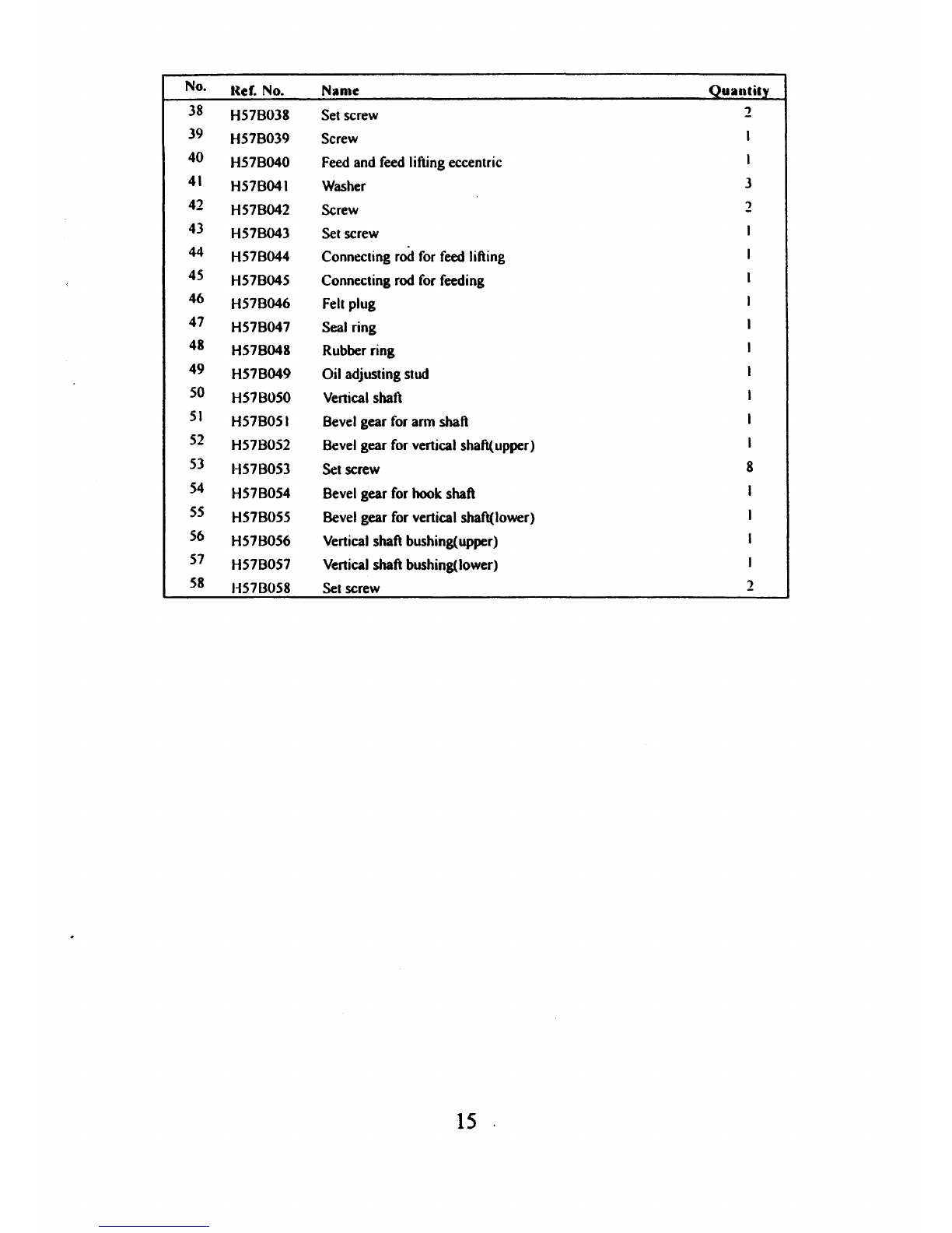
38 H57B038 Set screw 2
39 H57B039 Screw
40 H57B040
Feed
and
feed
lifting eccentric I
41
H57B041 Washer 3
42 H57B042 Screw 2
43 H57B043
Set
screw
44
H57B044 Connecting
rod
for
feed
lifting
45 H57B045 Connecting
rod
for
feeding
46 H57B046
Felt
plug
47 H57B047 Seal ring
48 H57B048 Rubber ring
49 H57B049 Oil adjusting stud
50 H57B050
Vertical
shaft
51
H57B051
Bevel
gear
for
arm shaft
52 H57B052
Bevel
gear
for
vertical shaft(upper) I
53 H57B053 Set screw 8
54
H57B054 Bevel gear
for
hook shaft
55
H57B055
Bevel
gear
for
vertical shaft(lower)
56 H57B056 Vertical shaft bushing(upper)
51
H57B057 Vertical shaft bushing(lower)
58 1-1578058 Set screw 2
15
.
From the library of: Superior Sewing Machine & Supply LLC
30
....
0'\
\
47 48
\
16
()
..
..,
~
~
0
;,
~
~
.....
'....,;
r-
-
~
~
,._
2
C)
>
2
0
"'
0
~
,;;
~
....
:z
Ci
.....
~
0
0
~
~
~
(j
...,...
,....
>
z
~
(J)
~
From the library of: Superior Sewing Machine & Supply LLC

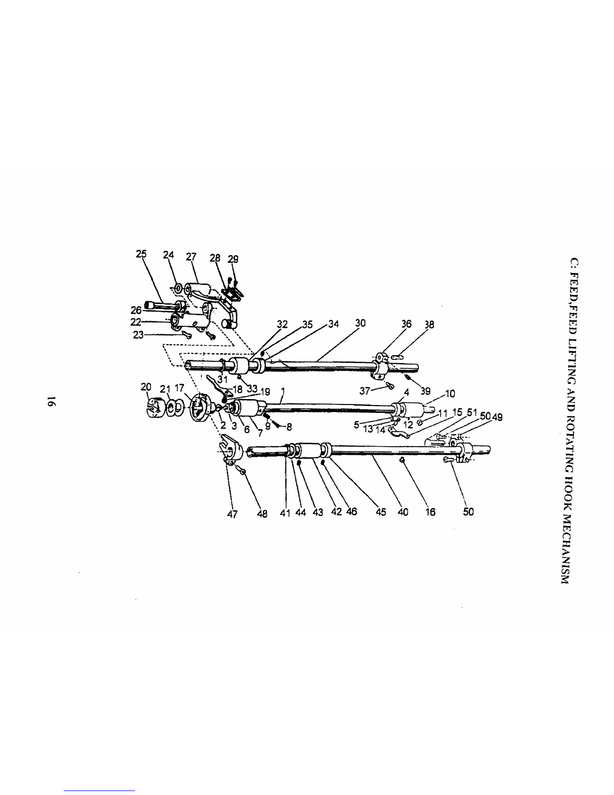
C: FEED,FEED LIFTING
AND
ROTATING
HOOK
MECHANISM
No. Ref. No.
Name
Quantity
I H57COOI Hook shat\ I
2 H57C002 Filter screw I
3 H57C003 Filter I
4 H57C004 Collar tor hook
shan
I
5 H57C005 Set screw 2
6 H57C006 Oil seal tor
ro~ating
hook shalt I
7 H57C007 Hook shaft bushing(left) I
8 H57C008 Oil adjusting screw I
Q H57C009
Spnng
for oil adjuster I
10
H57COIO Hook shaft bushing(right) I
II H57COII Screw for hook shaft bushing(right) 1
12
H57COI2 Oil pipe
tor
hook shaft bushing I
13
H57COI3 Plunger I
14
H57C014 Plunger
spring
I
15
H57COI5 Guide plate 1
16
H57COI6 Screw I
17
H57COI7 Rotating hook complete I
18
H57COI8 Rotating hook positioner I
19
H57C019 Screw 1
20 1157l'02() Buhhin case I
21
H57C021 Bobbin I
22 H57C022 Crank for feed bar I
23 H57C023 Screw 2
24 H57C024 Washer I
25 H57C025 Eccentric shaft tor teed bar crank I
26
H57C026 Screw I
27 H57C027 Feed bar I
28 H57C028 Feed
dog
I
29
H57C029 Screw 2
30
1·157C030 Feed rock
shan
I
31
H57C031 C-type stop
ring
I
32 H57C032 Bushing tor teed rock
shan
I
33 H57C033 Set screw I
34 H57C034 Collar I
35 H57C035 Set screw 2
36
H57C036 Feed rock
shaft
crank(right) I
37
H57C037 Screw I
17
From the library of: Superior Sewing Machine & Supply LLC
No.
R~f.
No.
Nam~
Quantity
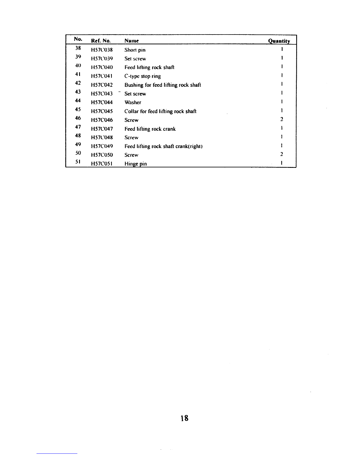
38 H57C038 Short pin I
39 H57C03Q Set screw
40
H57C040 Feed lifting rock shaft
41
H57C041 C-type stop ring
42 H57C042 Bushing for teed lifting rock shaft
43 H57C043 -Set screw
44 H57C044 Washer
45 H57C045 Collar tor feed lifting rock shaft
46
H57C046 Screw 2
47
H57C047 Feed lifting rock crank
48 H57C04H Screw
49 H57C049 Feed lifting rock shaft crank(right}
50 H57C050 Screw 2
51
H57C051 Hinge pin
18
From the library of: Superior Sewing Machine & Supply LLC
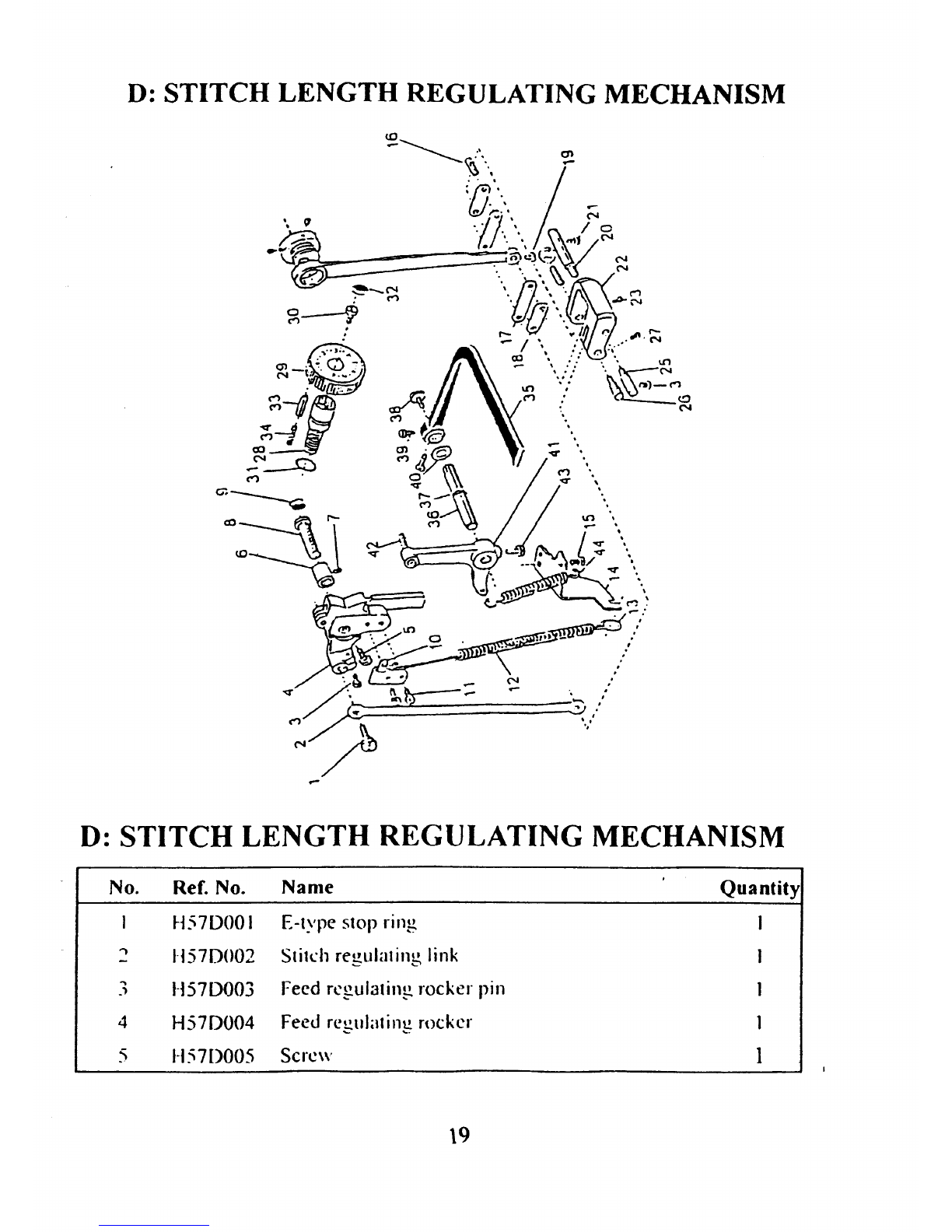
D:
STITCH
LENGTH
REGULATING MECHANISM
D:
STITCH
LENGTH
REGULATING MECHANISM
No. Ref. No.
Name
4
5
H57DOO
I E-type stop ring
H57D002
l-l57D003
Stih:h regula1 ing link
Feed regulating
rocker
pin
H57D004
Feed
regulating
rocker
1-157[)005
Sere\\·
\9
Quantity
I
From the library of: Superior Sewing Machine & Supply LLC
Table of contents


 Quick reference guide")


