The World Models Mfg 1/5 Piper J-3 Cub User manual

INSTRUCTION MANUAL
1/5 PIPER J-3 CUB
1/5 PIPER J-3 CUB
Warning !This model is not a toy.
It is designed for maximum performance. Please seek advice if one is not familiar with this kind
of engine powered precision model. Operating this model without prior preparation may cause
injuries. Remember, safety is the most important thing. Always keep this instruction manual at
hand for quick reference.
0.60-0.75 cu. in. displacement 2-stroke
Requires: 4-channel radio w/ 5 standard servos
* Specifications are subject to change without notice.*
Specifications
E
A
D
R
-
Y
T
-
T
S
O
O
-
F
M
L
L
Y
A
Wing Span
Wing Area
Flying Weight
Fuselage Length
84.0 in / 2130 mm
968 sq in / 62.5 sq dm
8.0 lbs / 3660 g
53 in / 1350 mm
0.70-0.81 cu. in. displacement 4-stroke
FACTORY PRE-FABRICATED
ALMOST-READY-TO-FLY (ARF) SERIES
MADE IN CHINA
A183RPO25561012
P.1
P. 3 -12
Check all parts. If you find any defective or missing parts contact your local dealer. Please DRY FIT
and check for defects for all parts that will require CA or Epoxy for final assembly. Any parts you
find to be defective after the gluing process may be difficult to remove for warranty replacement. The
manufacturer will replace any defective parts, but will not extend to the parts that are good before
gluing to defective parts during assembly. Warranty will not cover any parts modified by customer.
INDEX
BEFORE YOU BEGIN
PARTS LIST
ASSEMBLY
SAFETY PRECAUTIONS
P. 1
P. 2
P.12
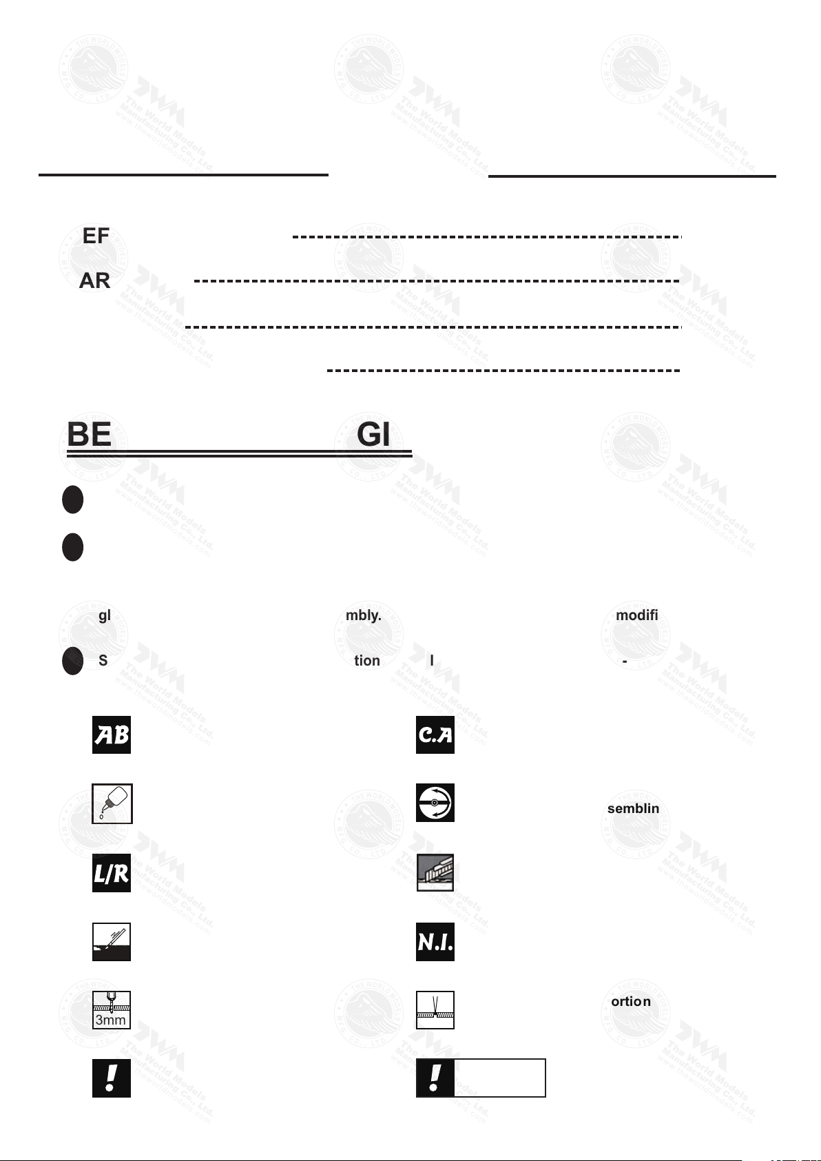
BEFORE YOU BEGIN
Read through the manual before you begin, so you will have an overall idea of what to do.
Symbols used throughout this instruction manual comprise of the following : -
1
2
3
Apply thread locker
Apply epoxy glue.
Pierce the shaded portion
covering film.
Apply instant glue
(C.A.glue, super glue.)
Ensure smooth non-bindin g
movement while assembling .
Do not overlook this symbol !
Assemble left and right
sides the same way.
Peel off shaded portion
covering film.
Drill holes with the specified
diameter (here: 3mm) .
Pay close attention here!
Cut off shaded portion.
Must be purchase d separatel y !
Warning!
3mm
1/5 PIPER J-3 CUB
1/5 PIPER J-3 CUB
A183RPO25561012

Parts List
P.2
1. MAIN WING -- 1 pair
2. SERVO MOUNTING PANEL (For Aileron) PL5310000 -- 1 pair
CLEVIS PL4112103 -- 2 pcs
STRAPER PL4112102 -- 2 pcs
FUEL TUBE Ø6x5mm -- 4 pcs
TRI-HORN M3x14mm (L) PL4111185 -- 2 sets
SCREW PB2x25mm -- 4 pcs
SCREW PWA2x8mm -- 8 pcs
PUSHROD Ø1.8x110mm w/ Threads (For Aileron) -- 2 pcs
3. SCREW PM3x16mm -- 4 pcs
WASHER d3xD7mm -- 4 pcs
MAIN WING STRUTS -- 1 pair
4. FUSELAGE -- 1 pc.
STABILIZER & ELEVATOR -- 1 set
5. VERTICAL FIN & RUDDER -- 1 set
6. TAIL LANDING GEAR --1 set
COPPER PLATE 1x10x34mm (For Flying Wire) -- 1 pc.
TAIL WHEEL Ø25mm -- 1 pc.
COLLAR Ø2.6mm w/ set screw -- 1 set
SCREW PA3x10mm -- 1 pc.
SCREW PA3x14mm -- 1 pc.
7. MAIN LANDING GEAR -- 1 set
SCREW PM3x12mm -- 2 pcs
SCREW PA3x12mm -- 14 pcs
WASHER d3xD7mm -- 4 pcs
MOUNTING PLATE 12x20mm PL4114020 -- 6 pcs
ALUMINUM PLATE 2mm -- 2 pcs
8. SCREW PA1.7x8mm -- 6 pcs
SCREW PM3x12mm -- 8 pcs
WASHER d3xD7mm -- 16 pcs
COLLAR Ø4.1mm w/ set screw -- 4 sets
M3 NUT -- 8 pcs
MAIN WHEEL Ø80mm -- 2 pcs
PLYWOOD 2x211.5x193.5mm (Main Landing Gear Cover) --1 pair
COPPER CLIPPER 0.5x8x13mm -- 8 pcs
9. ENGINE MOUNT PL5111050 -- 1 set
WASHER d4xD9mm -- 4 pcs
SOCKET HEAD SCREW M4x25mm -- 4 pcs
10. SCREW PM4x30mm -- 4 pcs
WASHER d4xD9mm -- 8 pcs
M4 NUT -- 8 pcs
THROTTLE PUSHROD Ø1.2x410mm -- 1 pc.
PLASTIC TUBE d2xD3x300mm -- 1 pc.
11. COWLING -- 1 pc.
TRANSPARENT 3D TEMPLATE -- 1 pc.
DUMMY ENGINE COVER -- 1 pair
SCREW PWA2.6x12mm -- 4 pcs
SILICON GROMMET d1.5xD6.5mm PL1265035 -- 4 pcs
SCREW PB2x22mm -- 2 pcs
SPINNER NUT Ø25mm HW2340001 -- 1 set
12. FUEL TANK 380cc PL1111380 -- 1 set
CABLE TIE 1.5x5x400mm -- 1 pc.
DOUBLE-SIDE TAPE 40x100mm – 1 pc.
13. PUSHROD Ø1.8x745mm w/ Threads (For Elevator) -- 2 pcs
SCREW PB2x14mm -- 6 pcs
CLEVIS PL4112103 -- 2 pcs
FUEL TUBE Ø6x5mm -- 2 pcs
TRI-HORN M3x14mm (L) PL4111185 -- 2 sets
14. PUSHROD Ø1.8x875mm w/ Threads (For Rudder) -- 1 pc.
SCREW PB2x14mm -- 3 pcs
CLEVIS PL4112103 -- 1 pc.
FUEL TUBE Ø6x5mm -- 1 pc.
TRI-HORN M3x14mm (L) PL4111185 -- 1 set
15. SCREW PM2x12mm -- 6 pcs
SCREW PA2x8mm -- 4 pcs
M2 NUT -- 6 pcs
WIRE Ø1x1480mm -- 1 pc.
FLYING WIRE BRACKET -- 6 pcs
FLYING WIRE BRACKET CLEVIS -- 4 pcs
EYE SCREW M1.8x6x12mm HW4133020 -- 4 pcs
COPPER TUBE d2.5xD3.2x8mm (For Rudder) HW4201302 -- 8 pcs
16. SIDE WINDOWS -- 1 pair
17. LINKAGE CONNECTOR Ø2.1mm w/ set screw HW7111060 -- 1 set
18. STRAPER PL4112102 -- 2 pcs
FUEL TUBE Ø6x5mm -- 2 pcs
PUSHROD Ø1.8x115mm (For Elevator) -- 1 pc.
PUSHROD CONNECTOR 4x9x20mm PL4410010 -- 1 set
SPONGE 60x70x122mm -- 2 pcs
19. PILOT PC001085B -- 1 set
SCREW PWA2x8mm -- 4 pcs
BALSA 2x118x173mm (For Pilot Stand) -- 2 pcs
20. WIND SHIELD -- 1 pc.
SCREW PWA2.3x12mm -- 10 pcs
SILICON GROMMET d1.5x6.5mm (For Wind Shield)PL1265035 -- 4 pcs
21. WING TUBE Ø14.5x508mm -- 2 pcs
SCREW PM3x18mm -- 2 pcs
SCREW PA3x18mm -- 2 pcs
WASHER d3xD7mm -- 4 pcs
22. SCREW PM3x12mm -- 2 pcs
WASHER d3xD7mm -- 4 pcs
M3 NUT -- 2 pcs
23. DECALS: A186SRDEC -- 1 set
TOUGHLON:--
TOUGHLON STL 201 BLACK
TOUGHLON STL 331 CUB YELLOW
A183RPO25561012

Main Wing
1
Aileron servo
2
PB2x22mm Screw
Wing Struts
3
140mm
100mm
497mm
Thread Locker
P.3
Bottom View
Pre-glued
Ø1mm pilot holes for World Models tri-horn pre-drilled. Please
look for pin-hole marks at under side of control surfaces.
Completed
Bottom View
Fuel Tube
Ø6x5mm
PB2x25mm
Tri-horn
M3x14mm(L)
Clevis
Pushrod
Ø1.8x110mm
1.5mm
8
PWA2x8mm Screw
2
Fuel Tube
Ø6x5mm
Straper
PWA2x8mm
PM3x16mm Screw
d3xD7mm Washer
d3xD7mm Washer PM3x16mm
A183RPO25561012
TWM Pl821 0010
CLEVIS WRENCH
PB2x25mm Screw
4
PB2x22mm
P.4
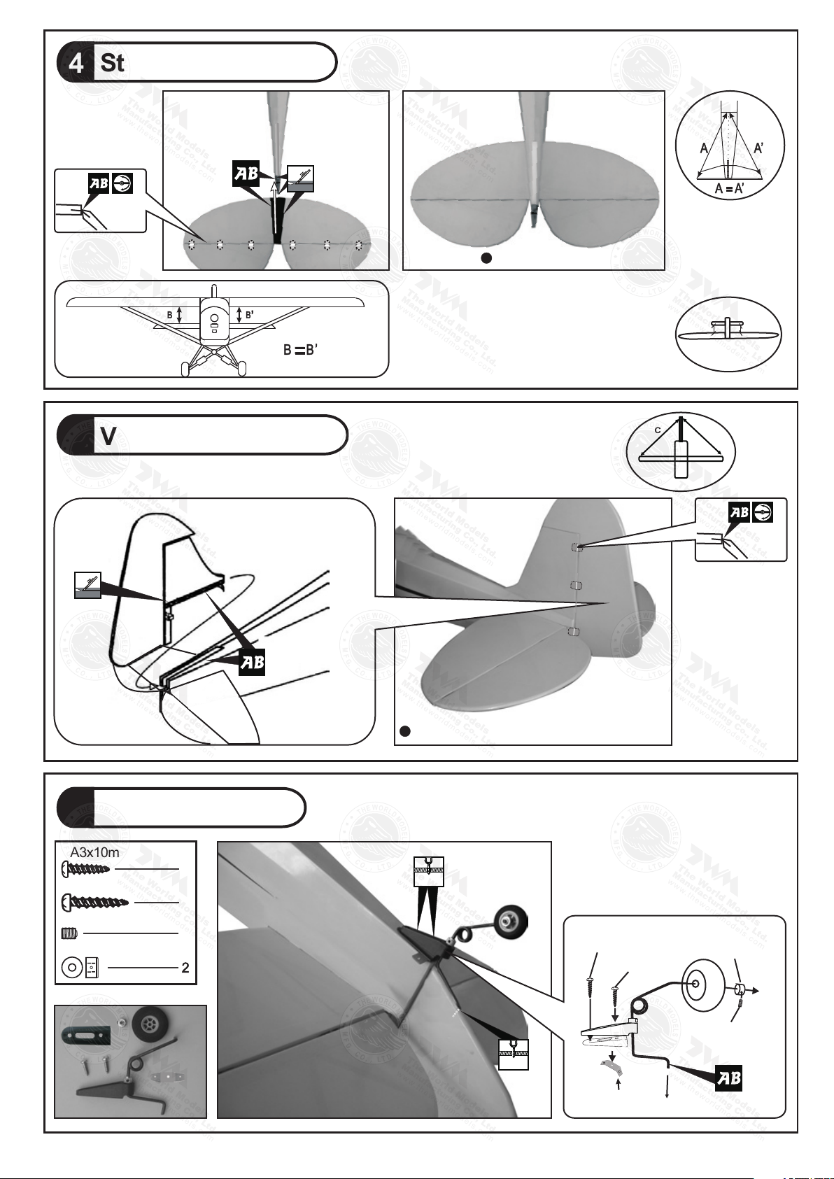
Stabilizer & Elevator
4
Vertical Fin & Rudder
5
Tail Landing Gear
6
PA3x10mm Screw
PA3x14mm Screw
2.6mm Collar
Temporary install the main wing, adjust
leveling of the stabilizer to make it as
parallel to the main wing as possible
Pre-glued
Completed
(Stabilizer)
(Main Wing)
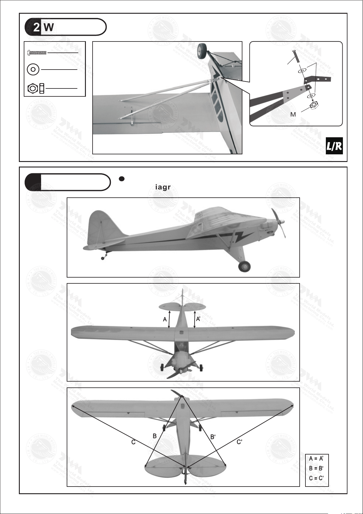
B B'
B=B'
Completed
C=C'
C'C
Pre-glued
1
1
1
3mm Set Screw
COPPER PLATE
1x10x34mm
PA3x10mm
PA3x14mm
2.6mm Collar
3mm Set Screw
2.5mm
1.5mm
A183RPO25561012

P.5
Main Landing Gear
7
PA3x12mm Screw
d3xD7mm Washer
14
4
PM3x12mm Screw
2
Bottom View
PM3x12mm
PA3x12mm
d3xD7mm
Washer
1.5mm
Front
Aluminum Plate
2 mm
Landing Gear
8
PM3x12mm Screw
PA1.7X8mm Screw
d3xD7mm Washer
M3 Nut
8
6
16
8
4
3mm Set Screw
4
4.1mm Collar
Bottom View
PA1.7x8mm
Collar
3mm
Set Screw
3mm
Set Screw
Collar
PM3x12mm
d3xD7mm
Washer
Copper Plate
0.5x12x20mm
M3 Nut
Front
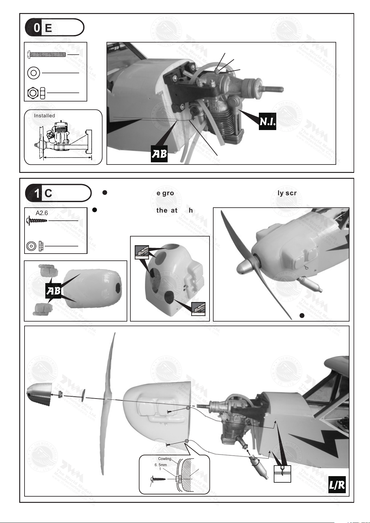
Engine Mount
9
d4xD9mm Washer
4
4
!
Blind nuts are off-centered to keep
the spinner at the fuselage axis.
Apply thread locker to screws.
M4x25mm
Socket Head Screw
Engine Mount
PL5111050
d4xD9mm Washer
M4x25mm Socket Head Screw
A183RPO25561012
P.6
Cowling
11
PWA2.6x12mm Screw
d1.5xD6.5mm
Silicon Grommet
4
4
1
4
2
Completed
3
1.5mm
Engine
10
PM4x30mm Screw
d4xD9mm Washer
4
8
M4 Nut
8
PM4x30mm
d4xD9mm Washer
M4 Nut
First insert the grommet to the cowling then apply screw.
Please refer to the attached
sheet for usage of the
transparent 3D template.
Throttle Pushwire Ø1.2x410mm
Installed Engine Position
132mm
5.2in
d1.5xD6.5mm
Grommet
Cowling
Fuselage
PWA2.6x12mm
A183RPO25561012

P.7
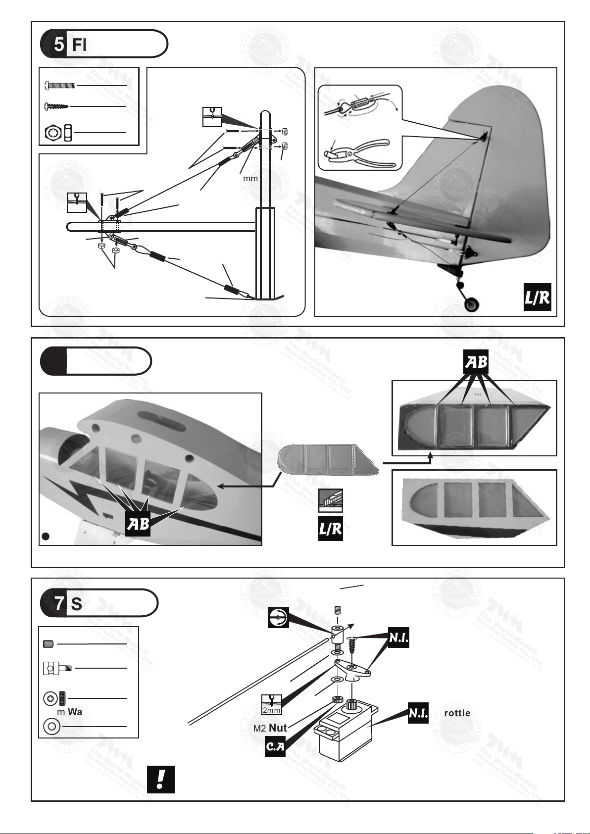
Rudder Pushrod
14
Fuel Tank
12
Fuel Tank
380cc
Completed
UP
Elevator Pushrod
13
195mm
90mm
139mm
15mm
PB2x14mm Screw
3
PB2x14mm Screw
6
PB2x14mm
Tri-Horn
M3x14mm(L)
Fuel Tube
Ø6x5mm
Clevis
Bottom View
Bottom View
Fuel Tube
Ø6x5mm
Clevis
Tri-Horn
M3x14mm(L) PB2x14mm
Ø1mm pilot holes for World Models tri-horn are pre-drilled.
Please look for pin-hole marks at under side of control surfaces.
Ø1mm pilot holes for World Models tri-horn are pre-drilled.
Please look for pin-hole marks at under side of control surfaces.
A183RPO25561012
TWM Pl821 0010
CLEVIS WRENCH
TWM Pl821 0010
CLEVIS WRENCH
Cable Tie
1.5x5x400mm Double-side Tape
1.5x5x400mm
P.8
Copper Tube
Press down the center
1/3 portion
Window B
Please refer to the attached sheet for linkage connector installation.
3mm
Throttle Servo.
2mm
Washer
2mm
Washer
Flying Wire
15
PM2x12mm Screw
6
4
PA2x8mm Screw
M2 Nut
6
Windows
16
Window A
Securely glue the windows to the fuselage.
Completed
Servo Set
17
1
1
3x3mm Set Screw
Linkage Connector
M2 Nut
2mm Washer
1
2
Throttle Pushwire
2mm
M2 Nut
M2 Nut
M2 Nut
PA2x8mm Clevis
d2.5xD3.2x8mm
d2.5xD3.2x8mm
PM2x12mm
PA2x8mm
2mm
2mm
COPPER PLATE
1x10x34mm
A183RPO25561012
P.9
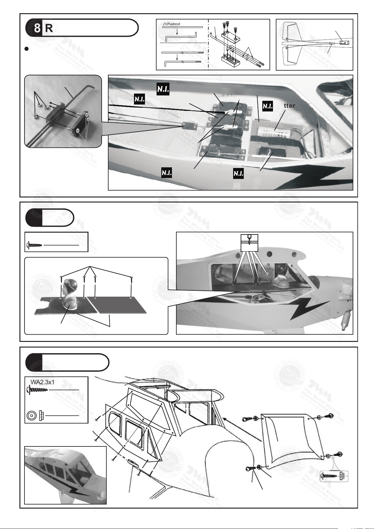
18 Radio Equipment
Wind Shield
20
PWA2.3x12mm Screw
d1.5xD6.5mm
Silicon Grommet
4
PWA2.3x12mm
d1.5xD6.5mm
Silicon Grommet
KM2x8mm
M2 Nut
Elevator Pushrod
Ø1.8x115mm
Fuel Tube
Ø6x5mm
Throttle Servo
Elevator Servo
Rudder Servo
Straper
Battery
Pilot
19
PWA2x8mm Screw
4
PC001085B Balsa 2x118x173mm
PWA2x8mm
1mm
Install and arrange the servo as
shown in the diagram.
Elevator Servo
Pushrod
Connector
J2(Pushrod Ø1.8x745)
J1(Pushrod Ø1.8x115) J1
J2
Receiver
10
Sponge
A183RPO25561012
P.10
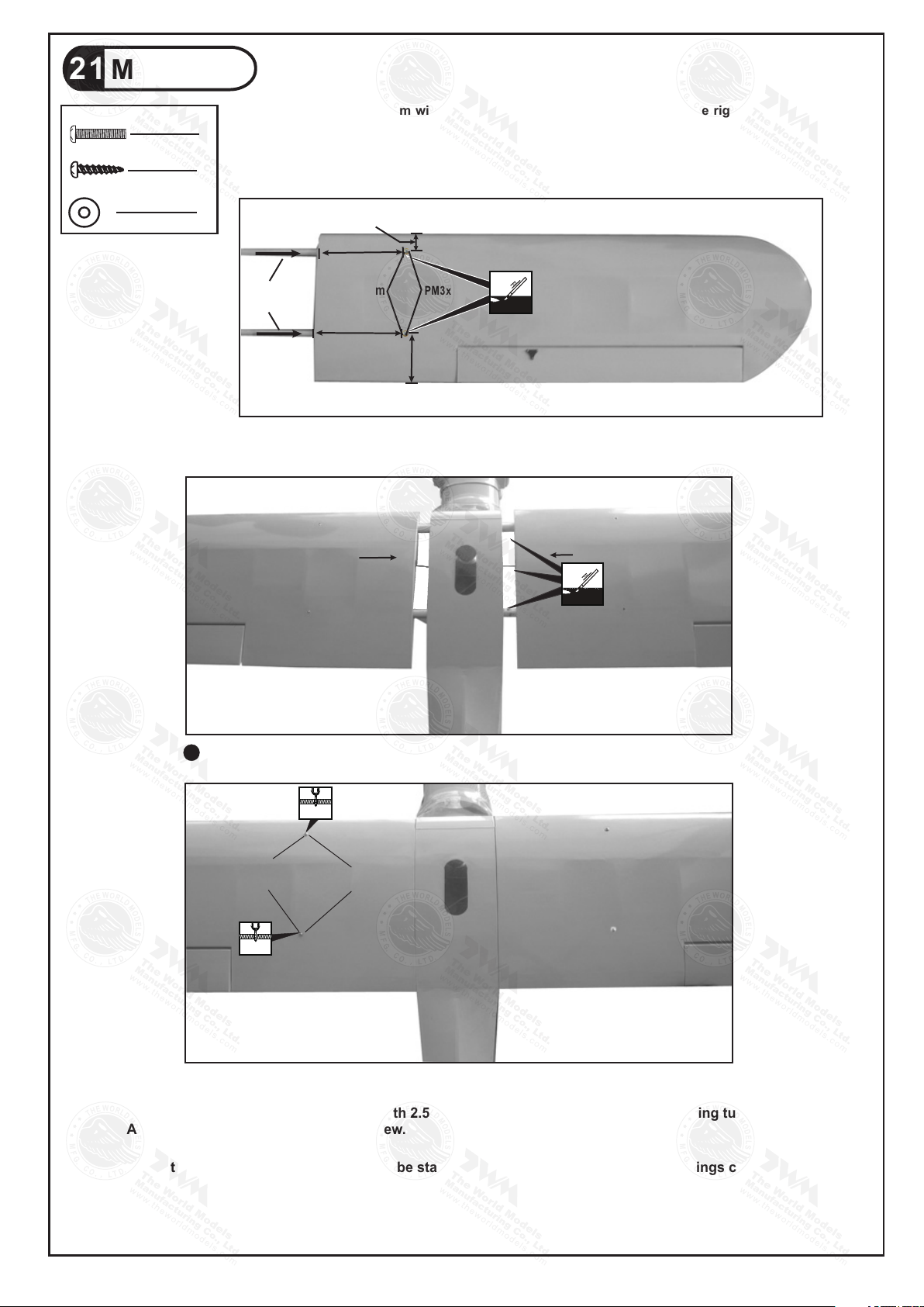
21 Main Wing
Step 1. Insert the aluminum wing tube with the pre-drilled hole end into the right wing. Align
the lines marked at the wing root and wing tube and apply the PM3 x 18mm machine screw
through the pre-drilled hole on top of the wing. ( please confirm the alignment of the hole by
putting a 2.5mm diameter rod through the pre-drilled wing hole before applying the screw )
The hole on the wing tube is pre-threaded, do not over tighten the PM3mm screw, the set up is for
future removal of the wing.
Step 2. Install the right wing to the fuselage by inserting the wing tube (now attached to
the right wing) through the fuselage, then install the left wing.
Step 3. Make sure the wings are resting against the fuselage tightly. Locate the pre-drilled 2.5mm
hole at top of left wing, and drill along with 2.5mm drill bit until it passes through the wing tube.
Apply the PA3 x 18mm self-tapping screw.
Note : It is recommended that the wing tube stays with the left wing. Removal of the wings could
be acheived by removing the right wing machine screw, the right wing then the left wing with
wing tube. If removal of wing tube from left wing is also required, it is recommended that
instead of applying self-tapping screw in step 3, you pre-tap with M3 thread cutter and apply M3
machine screw.
Wing Tube
D14.5x508mm
175mm
175mm
35mm
95mm
PM3x18mm
d3xD7mm
PM3x18mm Screw
2
2
PA3x18mm Screw
4
d3xD7mm Washer
Left Right
PA3x18mm d3xD7mm
2.5mm
2.5mm
Top View
A183RPO25561012
P.11
22 Wing Struts
PM3x12mm Screw
2
M3 Nut
2
4
d3xD7mm Washer
Wing Setting
M3 Nut
PM3x12mm
d3xD7mm
Washer
Adjust the wing and fuselage configuration as shown
in the diagrams.
23
A183RPO25561012
P.12
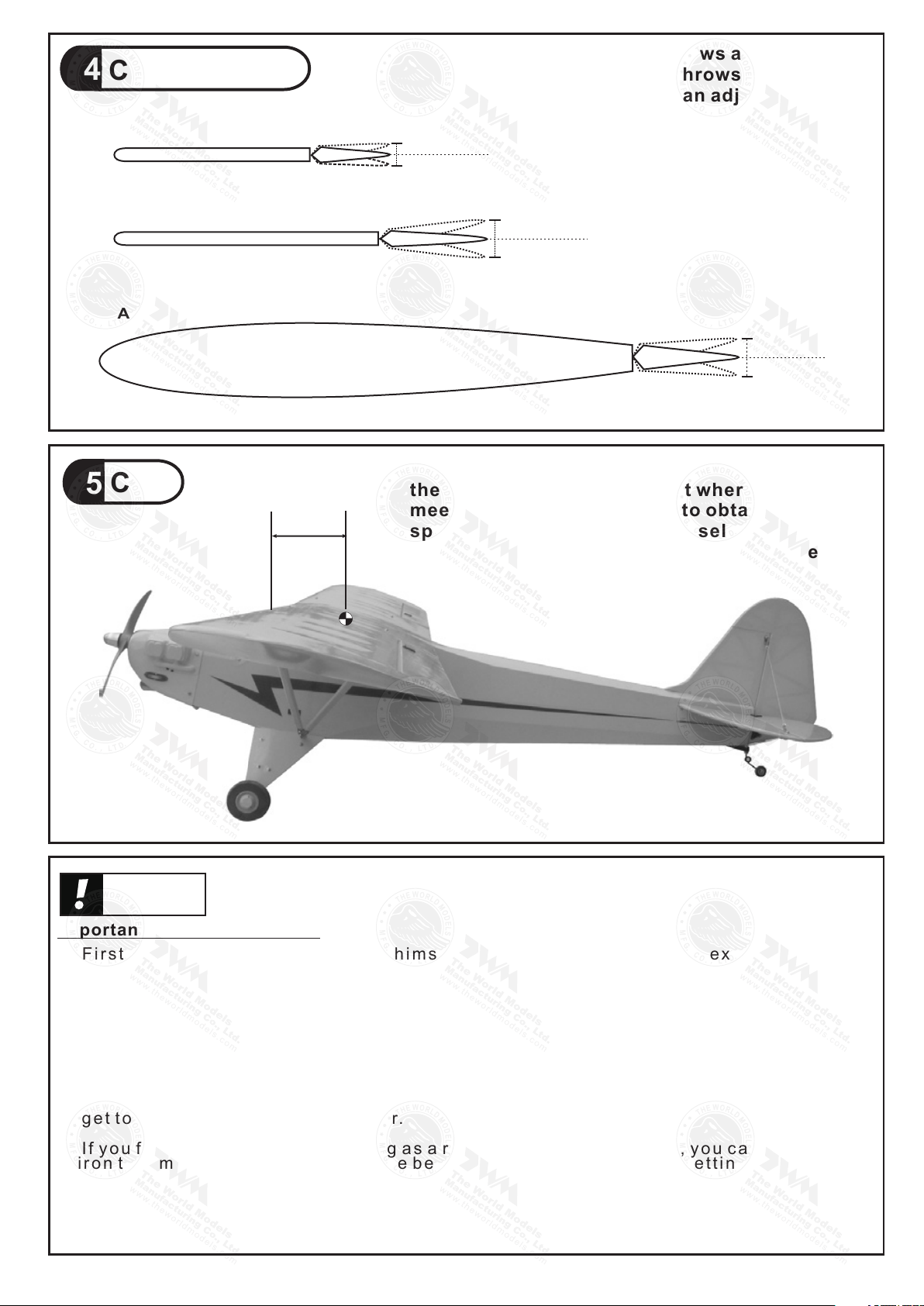
Control Throws
C. G.
24
25
Warning!
Adjust the control throws as shown in
the diagram. These throws are good for
general flying. You can adjust according
to your personal preference.
Aileron
20mm
Elevator
35mm
Rudder
60mm
60mm
35mm
20mm
The ideal C.G. position is 85mm (3.34in)behind
the leading edge measured at where the wing
meets the fuselage. In order to obtain the C.G.
specified, add weight to the fuselage or move
the battery position. Check the C.G. before
flying.
85mm
3.34in
Important Safety Precautions
# F i r s t t i m e f l y e r s h o u l d n e v e r f l y b y h i m s e l f / h e r s e l f . A s s i s t a n c e f r o m e x p e r i e n c e d
f l y e r i s a b s o l u t e l y n e c e s s a r y.
# P r e - f l i g h t a d j u s t m e n t m u s t b e d o n e b e f o r e f l y i n g , i t i s v e r y d a n g e r o u s t o f l y a b a d l y
p r e - a d j u s t e d a i r c r a f t .
# i s s p e c i a l l y d e s i g n e d t o b e p o w e r e d b y 2 C 0 . 6 0 - 0 . 7 5 o r 4 C 0 . 7 0 - 0 . 8 1
e n g i n e , u s i n g a m o r e p o w e r f u l e n g i n e d o e s n o t m e a n b e t t e r p e r f o r m a n c e . I n f a c t ,
over powered engine may cause severe damage and injuries.
# M a k e s u r e t h e a i r f i e l d i s s p a c i o u s , n e v e r f l y t h e p l a n e t o o c l o s e t o p e o p l e a n d n e v e r
g e t t o o c l o s e t o a r u n n i n g p r o p e l l e r.
# I f y o u f i n d w r i n k l e s o n t h e c o v e r i n g a s a r e s u l t o f w e a t h e r c h a n g e s , y o u c a n u s e h o t
i r o n t o r e m o v e t h e w r i n k l e s . P l e a s e b e g i n w i t h l o w e r t e m p e r a t u r e s e t t i n g a n d
g r a d u a l l y r a i s e t h e t e m p e r a t u r e u n t i l t h e w r i n k l e s a r e g o n e . To o h o t a n i r o n m a y
d a m a g e t h e c o v e r i n g . D o n ' t u s e h o t i r o n n e a r t h e s e a m s o r e d g e s , h o t i r o n w i l l
m e l t t h e g l u e a n d s h r i n k t h e c o v e r i n g a t t h e s a m e t i m e , c a u s i n g t h e s e a m s t o p u l l a w a y.
# C h e c k a n d r e - t i g h t e n u p a l l f a c t o r y a s s e m b l e d s c r e w s , u s e t h r e a d l o c k e r i f n e c e s s a r y.
1/5 PIPER J-3 CUB
1/5 PIPER J-3 CUB
A183RPO25561012
LINKAGE CONNECTOR
HW7111050 & HW7111060
Drill 2mm hole at servo horn.
Insert linkage connector
into servo horn.
Make sure shoulder of
screw is cleared from
servo horn.
Add washer to reduce
play if necessary.
Shoulder
Tighten up the round nut
against the shoulder. Apply
CA or permanent thread
locker.
After fastening the round nut, make sure that
the linkage connector can rotate freely.
Product Registration Form (US Customers)
We would like to share with you any relevant information regarding your model, including
product news and free upgrade parts when applicable. Please fill in the following and send to
1.Name:
2.Address:
3.Phone #: e-mail:
4.Model:
Wing QC# Fuselage QC#
(QC numbers are stamped on wing and fuselage)
5.Date of Purchase:
6.Store Name:
Please call AirBorne Models at 925 371 0922 for any assistance in filling this form.
Thank you very much for purchasing our product.
Air orne Models, 4749-K,Bennett Drive, Livermore, CA 94551 USAB .
A183RPO25561012
12
34
Usage of the transparent 3D template
This transparent 3D template
is used for position guidance
of the actual cutting of the
pre-painted cowling.
Simply cut the transparent 3D template to fit your engine and
exhaust pipe, then slide onto the actual cowling and use as
template to mark the openings required for final cutting.
A183RPO25561012
A183RPO25561012
Table of contents
Popular Toy manuals by other brands

Zapf Creation
Zapf Creation Baby Born 827987 manual

Fisher-Price
Fisher-Price ABC Shopping Cart instructions

Mega Bloks
Mega Bloks Collector Series instructions

FMS
FMS MAN-G0200 instruction manual

Mega Construx
Mega Construx Wonder Builders Pokemon Snubbull manual

Radica Games
Radica Games I7008 Pocket Poker instruction manual


