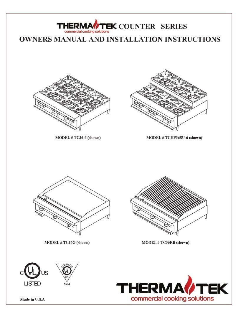
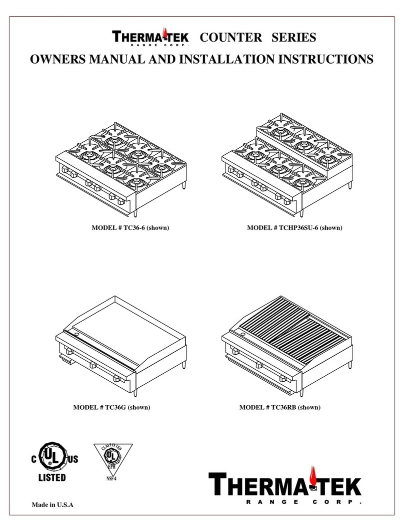
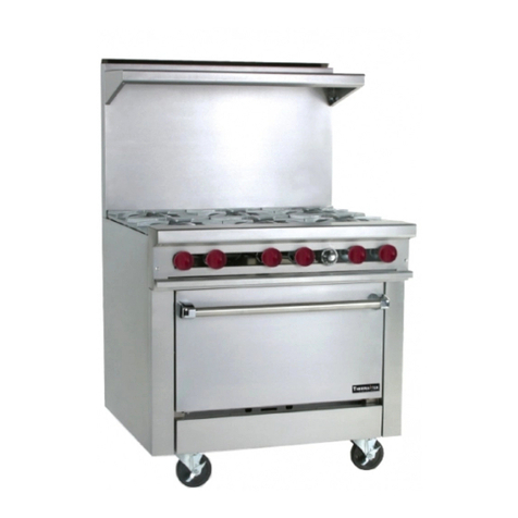
Therma-tek TMD36-6-1 Restaurant Series Specification sheet

RESTAURANT SERIES
OWNERS MANUAL AND INSTALLATION INSTRUCTIONS
U
LISTED
U
Made in U.S.A
CLUS L
MODEL # TMD36-6-1 (shown)

INTRODUCTION/ SAFETY PRECAUTIONS
Thank you for choosing your new THERMA-TEK Equipment. Our Products are designed to be safe and
reliable when properly cared for and used reasonably. Your service agency or dealer recommends periodic
inspections. Installation, maintenance, and repairs should be performed by your local authorized service
agency. This equipment is not intended for home use.
This equipment is for commercial use by trained professionals familiar with commercial cooking
equipment. It is the responsibility of the Supervisor or equivalent person to ensure that users wear
suitable protective clothing and safety gear. Caution: some parts of the equipment become very hot and
will cause burns if accidentally touched.
FOR YOUR SAFETY
DO NOT STORE OR USE GASOLINE OR OTHER FLAMMABLE VAPORS OR LIQUIDS IN THE
VICINITY OF THIS OR ANY OTHER APPLIANCE.
FOR YOUR SAFETY
If you smell gas:
1. Shut off gas to appliance.
2. Extinguish any open flame.
3. If odor continues, immediately call your gas
supplier.
Consult your local gas supplier for instructions to be followed in the event you smell gas.
Post these instructions in a prominent location.
WARNING:IMPROPER INSTALLATION, ADJUSTMENT ALTERATION, SERVICE AND/OR
MAINTENANCE CAN CAUSE PROPERTY DAMAGE, INJURY OR DEATH. READ THE
OWNERS/INSTALLERS MANUAL THOROUGHLY BEFORE INSTALLING OR SERVICING
THIS EQUIPMENT.
CALIFORNIA PROPOSITON 65 –WARNING
The burning of gas cooking fuel generates some by-products which are on the list of substancesknownby the State of
California to cause cancer or reproductive harm. California law requires businessesto warn customers of potential exposure to
such substances. To minimize exposure to thesesubstances,always operatethis unit according to theowners/installation
manual, ensuring you provide good ventilation when cooking with gas.
PLEASE RETAIN THESE INSTRUCTIONS FOR FUTURE REFERENCE
1

INSTALLATION AND SAFETY GUIDELINES
IMPORTANT
Safe and satisfactory operation of your equipment depends on its proper installation. Installation must
conform to local codes, or in the absence of local codes with the National Fuel Code ANSI Z223.1 (latest
edition).
All THERMA-TEK appliances are shipped with a gas pressure regulator packed with the unit. All units are
adjusted, tested, and inspected at the factory prior to shipment.
After uncrating, immediately check the equipment for visible signs of shipping damage. If such damage has
occurred, do not refuse shipment, but contact the shipper and file appropriate freight claims.
GENERAL
Installation of this equipment should be made by licensed and authorized personnel.
A manual gas shut-off valve must be installed in the gas supply (service) line ahead of the appliance
and gas pressure regulator installed in the gas stream for safety and ease of future service.
The gas pressure regulator supplied must be installed on the appliance prior to connecting the
equipment to the gas line. Failure to install a regulator will void the equipment warranty and result
in a potentially hazardous condition.
The appliance and its individual shut off valve must be disconnected from the gas supply system
during any pressure testing of that system in excess of ½ PSI.
The appliance must be isolated from the gas supply system by closing its individual shut off valve
during any pressure testing of the gas supply piping system at test pressure equal to or less than ½
PSI.
Please contact the factory, the factory representative, or a local authorized service company to
perform maintenance and repairs.
RATING PLATE
Information on this plate includes the model and serial number. When communicating with the factory
about a unit or requesting special parts or information, this information is required for proper identification.
Other information on the plate is the BTU/hr input of the burners, gas pressure in inches WC, and whether
the unit has orifices for natural or propane gas. Rating plate is located behind the lower front panel.
IMPORTANT: The appliance must be connected only to the type of gas identified on the rating plate.
GAS CONVERSION
We recommend that the appliance be ordered from the factory for the type of gas at the installation site.
When gas conversion is necessary contact the factory for a proper gas conversion kit.
2

INSTALLATION AND SAFETY GUIDELINES
CLEARANCES
The unit must be kept clear of all combustibles.
The unit must be installed with the 6” legs or casters supplied for proper operation.
Minimum clearance from combustible construction:
Side Back
oOpen top 12” 6”
oHot Top 6” 6”
oGriddle 6” 6”
oBroiler 6” 6”
Minimum clearance from non-combustible construction: 0” Side, 0” Back
LEVELING
A carpenter’s spirit level should be placed on the cooking surface and the unit leveled side-to-side, and front
to back. If it is not level, burner combustion may be erratic or the unit may not function efficiently.
AIR SUPPLY AND VENTILATION
The appliance must be installed under a ventilation hood.
The area around the appliance must be kept clear to avoid any obstructions of the flow of combustion and
ventilation air as well as for ease of maintenance, service, and proper appliance operation. Keep clearance
for openings into the combustion chamber and adequate air supply. Means must be provided for any
commercial, heavy duty-cooking appliance to exhaust combustion wastes to the outside of the building.
Air movement should be checked during installation. Strong exhaust fans in the hood or in the overall air
conditioning system can produce a slight draft in the room, which can interfere with pilot or burner
performance. If pilot or burners problems persist make up air openings or baffles may have to be provided
in the room.
Filters and drip troughs should be part of any industrial hood, but consult local codes before constructing
and installing any hood. The duct system, exhaust hood, and filter bank must be cleaned on a regular basis
and kept free of grease.
ALTITUDE
The appliance input rating (BTU/hr) is for elevations up to 2000 feet. For elevations above 2000 feet, the
rate should be reduced 4% for each 1000 feet above sea level. The correct orifices are installed at the
factory if the operating altitude is known at the time of sale.
3

INSTALLATION AND SAFETY GUIDELINES
GAS CONNECTION
The gas supply (service) line must be at least the same size or larger than the inlet line of the appliance.
THERMA-TEK restaurant series equipment is supplied with a ¾” NPT Schedule 40 inlet. Sealant on all
pipe joints must be resistive to LP gas.
MANUAL SHUTOFF VALVE
A manual shut-off valve must be installed in the gas service line ahead of the appliance and regulator in the
gas stream and in a position where it can be reached quickly in the event of an emergency. The manual shut-
off valve is supplied by the installer.
PRESSURE REGULATOR
All commercial cooking equipment must have a pressure regulator on the incoming service line for safe and
efficient operation, since pressure may fluctuate on local demand. A regulator is supplied with the
appliance. Failure to install a pressure regulator will void the equipment warranty. The regulators are
adjusted at the factory, 5.0” WC for natural gas, and 10.0” WC for propane gas. Ensure the supply pressure
is within the following range: Natural Gas 6.0” WC to 13.0” WC / Propane Gas 11.0”WC to 13.0” WC.
Only qualified service personnel with proper test equipment must make any adjustments to the regulators.
RIGID CONNECTIONS
Double check any installers supplied gas pipes visually and blow them out with compressed air to clear any
dirt particles, threading chips, or any other foreign matter before installing a service line. Those particles
will clog orifices when gas pressure is applied. All connections must be sealed with a joint compound for
LP gas, and tested with a soapy water solution before lighting any pilots.
FLEXIBLE COUPLINGS, CONNECTORS AND CASTERS
If the unit is to be installed with flexible coupling and or quick disconnect fittings, the installer must use a
heavy duty commercial flexible connector at least ¾” NPT (with suitable strain relief) in compliance with
the standard for connectors for movable gas appliances, ANSI Z21.69-1987 and Addenda Z2.169a-1989 (or
latest edition) or connectors for movable appliances, CAN/CGA-6.16 (or latest edition) and quick
disconnect device must comply with the standard for quick disconnect devices for use with gas fuel,
ANSI Z21.41-1989 (or latest edition) or quick disconnect devices for use with gas fuel, CAN1-69 (or latest
edition). Adequate means must be provided to limit the movement of the appliance. Domestic connectors
are not suitable.
When the appliance is supplied with casters and is connected to the supply piping by means of a connector
for movable appliances, and if disconnecting the restraint is necessary, this restraint must be reconnected
after the appliance is returned to its original installation position. The strain relief is a cable attached to the
rear of the appliance.
4

RESTAURANT RANGE BACKGUARD MOUNTING INSTRUCTIONS
KIT INCLUDES:
(2) PN 31079 BACKGUARD SUPPORT
(4) PHILLIPS HEAD SHEET METAL SCREWS
FIGURE 1: SHELF AND BACKGUARD MOUNTING ASSEMBLY TO RANGE
FIGURE 2: STEP ONE DIAGRAM
FIGURE 3: PN 31079 BACKGUARD SUPPORT ASSEMBLY TO EXISTING PART
FIGURE 4: STEP 2 DIAGRAM
5
FIGURE 2
STEP 1
REMOVE BACK PANEL FROM SDHS BY
REMOVING(6) PHILLIPS HEAD
SCREWS AND (2) 7/16” HEX HEAD
BOLTS AS SHOWN IN FIGURE 2.
FIGURE 3
FIGURE 4
STEP 2
FLANGE EXISTS ON RANGE AT THE
LOCATION DIRECTED BY ARROW. REMOVE
(2) EXISTINGSHEET METAL SCREWS FROM
FLANGE AND ATTACH BACKGUARD
SUPPORT HERE WITH EXISTING SCREWS AS
SHOWN IN FIGURE 3. USE (2) PHILLIPS
HEAD SHEET METAL SCREWS FROM KIT TO
SECURE ASSEMBLY TO SHELF UPRIGHT
AND INNER BURNER AS SHOWN IN FIGURE
4. BOX SIDE PROCEDURE IS DONE TO
BOTH SIDES OF SDHS.
NOTE: WHEN LOCATING HOLES FOR
PLATE, BE SURE SDHS IS STRAIGHT AND
PLUMB.
REINSTALL BACK PANEL.
EXISTINGFLANGE
BACKGUARD
SUPPORT
(2) EXISTING
SHEET METAL
SCREWS
FIGURE 1

INITIAL START-UP
All THERMA-TEK appliances are adjusted and tested before leaving the factory. Adjustments and
calibrations may be necessary upon installation to meet local conditions, low gas characteristics; problems
caused by rough handling or vibration during shipping, and are to be performed only by qualified service
personnel. These adjustments are the responsibility of the customer and or dealer and are not covered by
our warranty.
Check all gas connections for leaks with a soapy water solution before lighting pilots. Do not use an open
flame to check for leaks. Putting an open flame beside a new gas connection is extremely dangerous.
Before lighting any pilots, make sure that burner valves and thermostats are in the off position.
LIGHTING THE PILOTS
CAUTION: When lighting the pilots and checking for leaks, do not stand with your face close to the
Combustion chamber.
OPEN TOP:
Remove top grates
Make sure pilot adjust valve located on the manifold is open.
Light the pilot and adjust flame to approximately ½”.
GRIDDLE/HOT TOP:
Looking through slot in the valve panel, locate pilot lighting holes in the burner front shield.
Make sure pilot adjust valve located on the manifold is open.
Light the pilot and adjust flame to approximately 3/4” high.
BROILER:
Remove grates.
Make sure pilot adjust valve located on the manifold is open.
Light the pilot and adjust to approximately ¾” high.
OVEN:
Access the pilot behind the lower front panel by lifting the panel upward and rotating forward.
Locate the oven safety and depress and hold the red button on the safety.
Repeatedly push the igniter button until the pilot lights.
Continue to hold the red button on the safety until pilot stays lit, approximately 30 seconds.
If the pilot goes out, turn all knobs to the off position, and wait 5 minutes before trying to relight the
pilot.
SHUTDOWN
Nightly shutdown: Turn burner valves and thermostat to off position, pilots will remain lit.
Complete shutdown: Turn burner valves and thermostats to off position. Turn main gas supply to
range off.
6

OPERATING INSTRUCTIONS
BEFORE USE
All units are wiped clean with solvents at the factory to remove any visible signs of dirt, oil or grease
remaining from the manufacturing process.
Open Tops & Broilers
The top grates should be removed and washed before use. With these removed it will be possible to remove
plastic ties holding the burners in place for shipment.
Hot Top
The hot top is made of cast iron and should be seasoned before use. To season, pour a small amount of
cooking oil on the top. With a cloth, spread the oil over the entire surface to create a thin film. Wipe off
any excess oil with a cloth. Turn burner on very low and allow top to heat up gradually for about 2 hours.
Repeat this procedure a second time before regular use. This will resist cracking of the cast iron and ensure
a longer life.
Griddle
New griddles should be seasoned as follows:
1. Clean the griddle surface thoroughly with hot soapy water to remove the protective oil coating wiped
on at the factory.
2. Rinse with a mixture of ¼ cup vinegar to one-quart water.
3. Spread unsalted shortening or liquid frying compound evenly over the entire griddle surface.
4. Turn all griddle burners to medium or thermostats to 350 degrees and wait until the shortening
begins to smoke, then turn the burners off.
5. Rub the now melted shortening into the griddle surface with a cloth covering the entire surface.
6. Let the griddle cool, then repeat steps 3,4, & 5.
7. When the griddle is cool after the second seasoning, wipe it once again with a thin film of shortening
or cooking oil.
Oven
Before using the new oven be sure all packing material is removed from the oven. Remove any plastic ties
that may have been used to hold the oven racks in place for shipping. Wipe down the oven interior of any
dirt or debris that may be left from shipping. On initial lighting, turn the oven to 250 degrees and operate
for one hour, then reset the thermostat to its maximum and operate for another hour. This will burn off any
solvents remaining on the unit. At the end of this second hour, turn the thermostat off, open the door and let
cool.
7

OPERATING INSTRUCTIONS
OPERATING SUGGESTIONS
Open Tops
Open top burners are quickly lighted and require no preheating time. Light only as many burners as needed.
Hot Top
Heat the hot top thoroughly before using. During slow periods the top can be kept warm with the burners
turned partially down.
Griddle
Heat the griddle thoroughly before using. During slow periods the top can be kept warm with the burners
turned partially down, or heat only the portion of the griddle required.
Broiler
Allow the grates to thoroughly heat before using. During slow periods heat only the portion required.
Oven
Allow time to preheat ovens before using (25 min. at 400 F). If used properly, the automatic temperature
control will cut gas costs. Do NOTrun on maximum heat all the time. Turn the thermostat down to 250 F
when the oven is idling, or turn it off when not in use.
Moderate oven temperatures will produce better food, reduce shrinkage and keep maintenance costs down.
Using a low temperature for roasting (about 325 F) will reduce meat costs by reducing shrinkage. A pan of
water may be placed on the oven bottom. This water supplies humidity to reduce shrinkage. If necessary,
add water during roasting.
8

CARE AND CLEANING
Any piece of equipment works better and lasts longer when properly maintained. Cooking equipment is no
exception. Your THERMA-TEK appliance must be kept clean during the workday and thoroughly cleaned
at the end of the day.
OPEN TOP
Remove grates and burners and wash thoroughly with hot soapy water. Be sure to clean burner ports
by using a piece of wire
Make sure air shutter openings are clear of any debris.
Make sure pilot flashtube is clear.
Empty crumb trays.
HOT TOP
Wipe the top while still warm with a soft damp cloth or other grease removing material to remove
spillovers, grease etc. before they burn in. A crust on top of the range looks unsightly and slows
down speed of cooking because it reduces the flow of heat to the utensil. If necessary scrape the top
with a nylon scraper.
GRIDDLE
Scrape with a nylon griddle scraper to remove cooked on spills. Use a fine-grained stone only when
absolutely necessary.
Wipe away any griddle stone dust and food particles with a cloth.
Wash with hot soapy water, and then rinse with vinegar and water solution.
Then rinse again with clear water.
Re-oil with shortening or liquid frying compound.
Remove grease can, empty, and clean it thoroughly with hot soapy water.
Never flood the griddle with cold water. This promotes griddle warping and can cause the griddle
plate to crack if continued over a long period of time.
BROILER
Remove large pieces of food residue and carefully scrape spillovers from the drip tray below the
cooking surface.
Cast iron grates should be scraped with a wire brush frequently, and periodically soaked in hot water
to remove grease from the pores of the cast iron. Never expose the grates to extreme heat for the
purpose of burning off excess grease. This practice will shorten the life of the grates.
The lava rock in the Char-rock broiler are highly porous and relatively self cleaning. High heat will
effectively clean and burn off grease. The lava rock should be turned over about every week
depending on the amount of cooking being done and the type of food being prepared.
OVEN
Wipe oven door often during the workday with a damp cloth.
At the end of the workday wipe the oven interior with a damp cloth.
Soften any built up debris by soaking with a damp cloth. Scrape if necessary with a nylon scraper.
STAINLESS STEEL
All stainless steel body parts should be wiped regularly with hot soapy water during the day and with
a liquid cleaner designed for this material at the end of each day. Do not use steel wool, abrasive
cloths, cleansers, or powders to clean stainless steel surfaces. If it is necessary to scrape stainless
steel to remove encrusted materials, soak in hot water to loosen the material, and then use a nylon or
wood scraper to loosen debris. Never use a spatula, knife or any other metal tool to scrape stainless
steel. These tools will scratch the stainless steel.
9

TROUBLESHOOTING
PROBLEM
POSSIBLE CAUSE
SOLUTION
Burner flame to large
Incorrect pressure setting or
orifice
Check pressure setting and orifice.
Burner flame soft and yellow
tipping
Insufficient primary air
Check air shutter setting.
Flame lifts off burner ports
Excessive primary air
Check air shutter setting.
Flame lights back to orifice
Excessive primary air
Check air shutter setting.
Delayed ignition
1) Pilot flame too small
2) Burner ports blocked
3) Incorrect air shutter setting
4) Incorrect pressure setting
5) Pilot lighter tube dirty or
blocked
1) Check pilot flame length.
2) Clean burner ports.
3) Check air shutter setting.
4) Check pressure setting.
5) Clean tube.
Pilot burner will not ignite
1) Pilot blocked or dirty
2) Pilot adjusting screw closed
1) Clean pilot.
2) Open & adjust flame length.
Griddle too hot or not hot enough
Thermostat out of calibration
Check calibration.
Oven too hot or not hot enough
Thermostat out of calibration
Check calibration.
Oven pilot burner will not ignite
1) Pilot orifice is blocked
2) Flame length too short
3) Loose thermocouple
connection
4) Faulty thermocouple
5) Faulty flame safety device
1) Clean pilot orifice and lines.
2) Check flame length & adjust.
3) Tighten connection.
4) Replace thermocouple.
5) Replace safety valve.
HOW TO OBTAIN SERVICE
For warranty service, contact your local THERMA-TEK authorized service agency. Provide him or her
with the Model #, Serial #, date of installation, and a brief description of the problem. If you need assistance
locating the authorized service agency in your area, contact your local dealer. He or she will have a listing
of authorized dealers in your area, or on the web www.therma-tek.com
We want you to remain a satisfied customer. If a problem arises that cannot be resolved to your satisfaction,
please contact our customer service at:
570-455-3000
570-455-9491 (fax)
877-THERTEK (toll free)
Or e-mail us at info@therma-tek.com
For Technical support call: 570-455-3000
10

The Therma-Tek Corporation warrantsitsnewproduct (s) to be free fromdefectsin
material andworkmanship for aperiodof one(1) year fromthe originaldateof
purchase, not toexceedeighteen (18)monthsfromshipment fromthe Factory to
Dealer or Owner–User providedproofof purchaseandinstallation datebeing
providedto Therma-TekCorporationprior to workbeingperformedby an
AuthorizedTherma-TekService agency.Thiswarrantyshall be subject to the
Followingconditionsandlimitations.
1. This warrantyislimitedtoproduct (s) soldto the original commercial user.
2. The liabilityof Therma-Tek under this warrantyislimitedto, at Therma-Tek’s
option,the replacement or repair ofanypartfoundby Therma-Tekor an
authorized service agency to notbe as warrantedherein, providedthatwritten
notice of defectsshall be suppliedto Therma-Tekwithin fifteen(15) daysof its
occurrence.
3. Therma-Tekshall bear normallaborandshippingchargesincurredin such repair
or replacement to theextentthatsuch isperformedwithina fifty(50) milesfrom
an office of an authorizedservice agency of Therma-Tek,except that such
obligation tobear labor chargesshallnotapply to productsor partsinstalled
outside the continental UnitedStates. Shouldservice be requiredat times which
normally involve premiumlabor rates,the Owner-User shall be chargedfor the
difference betweennormal service/shipping rates andsuch premium/shipping
rates. All warrantedpartswill be shipped standardground; anythingother than
groundwill be at the expense of Owner-User.
4. Therma-Tek shall have noobligation astoany product (s) whichhavebeen
misapplied, (includinginstallationforresidential use), mis-handled, damaged,
abused, subjectedto harsh chemical actionor poor waterquality,modifiedby an
unauthorized service personnel,damagedby flood, fireor otheractsofGodor
which have the serial number removedor altered.
5. Adjustmentssuch ascalibrations, airshutteradjustment andadjustmentstopilots
andburners, conversions, leveling, tighteningof fasteners orutility connections,
are the responsibility ofthe Owner-User(customer), Dealer orCertifiedLicensed
installer andnot that of Therma-Tek.
6. Thesewarranty periodsratherthanone(1) year periodhereinprovidedfor other
parts shall applyforthe product (s) listed.
Porcelainenamel andpaint–90daysfrom purchase/installation.
Rubber seals, door seals, chain mechanisms, light bulbsandgaskets–90 daysfrom
purchase/installation.
Cast-iron parts–90 daysfrompurchase/installation.
Sight glass, spark Ignitors, andbroiler briquettesanddrip shields–90daysfrom
purchase/installation.
Mobile Food Truck/ Trailer–equipmentwill have 30 Dayswarrantyafterpurchase
for any Therma-Tek product (s) installedon mobile kitchens;or usedfor Mobile
FoodService.
All service issuesneedto be accompaniedby proofof purchaseandcopyof
certification from gas installer’s receipt of compliance/ installation.
7. Therma-TekRange AuthorizedService Agencies under contract guarantee
Warrantywork within thirty(30) daysforreplacementpartsand/or issues after
Installation andreceiptof service rendered. Therma-Tek Range guarantees
Replacementpartsandorservicelabor for ninety(90) daysafterservice receipt
For service work beingperformedby an AuthorizedService Agency andunit
Beingrepairedandgoodworkingcondition. AuthorizedService Agencymay
Require a credit cardbefore enteringpremises fornon-warrantedissues.
8. This states the exclusive remedyagainst Therma-Tekrelatingtothe product(s)
Whetherin contractor in tort or under any otherlegaltheory,andwhether
Arisingout of warranties, representations, instructions, installationsor defects
From any cause.
9. Thiswarrantyandthe liabilitiesset forthherein areexclusiveandin lieuof
Allof their liabilities andwarranties,expressedor implied, includingbut not
Limitedto, impliedwarrantiesor merchantability andfitnessforparticular
Purpose andconstitutes the only warrantyof Therma-Tekwith respect tothe
Product (s).
10. Therma-Tekshall notbeliable, whetherin contract or in tortor under any
Other legaltheory,forlossof use, revenueor profit, orfor substituteuse of
Performance,forincidental indirect, or specialorconsequential damagesor
For any other lossof costof similartype.
WARRANTY REQUIREMENT
For reliable operation and for your own safety, this professional cooking equipment must be installed by a
certified/ licensed contractor.
Failure to comply will void any written or implied warranty.
Should the equipment require service during the standard warranty period, the receipt proving certified
installation?
Must be made available to Therma-Tek Range for verification.
If installation was not performed be a certified/ licensed contractor, be prepared to submit a major credit card
For payment for proper installation prior to service.
TERMS AND CONDITIONS
Terms: Net 30 days subject tocredit approval.All amounts past due are subject to 1.5% permonth service charge will be appliedto all invoices 30 days
Or more past due.
FOB: Factory
Prices:All prices are subject tochange without notice. Prices do not include sales or any other local statetax.
Shipments:Shipments must beinspected for damaged cartons and shortages promptly noteduponreceipt and also noted on delivery receipt. All
Shipments shall be inspectedfor hidden or concealed damage and noted and reportedwithin ten (10) days tocarriers and request an
Inspectionat once.
Therma-Tek’s responsibility for shipments ceases with acceptance by carriers and to Dealer or Owner-User.Once product is received free
And clear; Therma-Tek is not responsiblefor any hidden or concealed damages for equipment or part(s). Noclaims for damaged or missing
Will be recognized unless writtennotice to Therma-Tek within ten(10) days of receipt. Therma-Tek is not responsible of repair of damaged
Goods created during transit,delivery and installation or created by acts of God.
Goods: Returned goods are subject toa 20% re-sticking charge and the cost of reconditioning. Return Authorization (“RA”) number for all returns must
Be placed on label and shippedback to Therma-Tek. Merchandise without an RA number will not be accepted. All authorizedreturns must be
Sent freight pre-paid.All orders over sixty (60) days will not be accepted. Customunits built to buyerspecifications may not be returnedor
Cancelled.
Rush Shipments: Ordersrequiringnext, 2nd or 3rd day priority shipments must be placed by 1:00 PM EasternStandard Time. Rush shipment cannot be
Guaranteed.
Note: Since continuing product improvement is a Therma-Tek policy, the factory reserves the right to change specifications, designs and material
Without notice.
THERMA-TEK TERMS OF SALE AND ORIGINAL EQUIPMENT WARRANTY FOR
INSTALLATIONIN THE U.S.A. ORIGINAL WARRANTY
Table of contents
Other Therma-tek Range manuals
Popular Range manuals by other brands

Thermador
Thermador Pro Grand PD30 Care and use manual
Electrolux
Electrolux EI30GF35JSA Use & care guide
Frigidaire
Frigidaire CGLEF379GC installation instructions
Whirlpool
Whirlpool 98014106 installation instructions

Kenmore
Kenmore 790.9258 Use & care guide
Frigidaire
Frigidaire FEF326A Factory parts catalog
