THERMA Big Dipper 40000 Series User manual
40000 Series Big Dipper®
Technical Support Instructions
2 • info@thermaco.com • www.big-dipper.com • 1-800-633-4204 Copyright 2014 • Big Dipper® Thermaco, Inc®
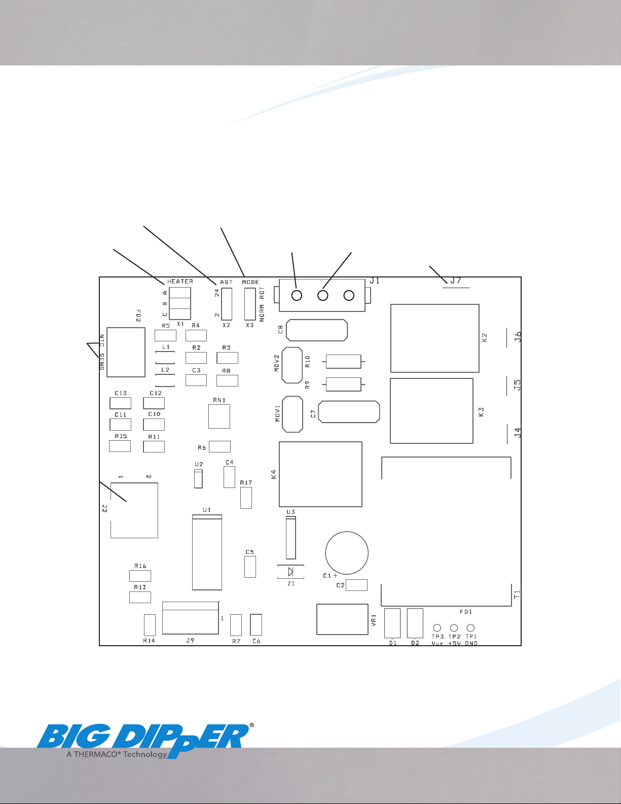
Board Diagram for 40000 Series Big Dipper
Printed Circuit Board
The 40000 Series Big Dipper uses a Digital Control Timer with pre-set skim times and frequencies hard
programmed into a circuit board within the Center Lid Assembly. Below you will nd a diagram of
the board, standard settings for various modes and the procedures for changing these settings on the
board.
Heater Settings
(page 3)
AST Modes
(page 3) Skim Operation
Settings (page 4)
Ribbon Cable
(to Push Button
Interface)
Heater Connection
Motor
Connection
Board Power
(115 V )
Board Power
(220-240 V)
Neutral
(to Power
Supply Cord)
Thermistor
Connections
AST Solenoid
Connection

Copyright 2014 • Big Dipper® Thermaco, Inc®. • 3info@thermaco.com • www.big-dipper.com • 1-800-633-4204
Heater Settings
There are three separate options for heater operation in the 40000 Series Big Dipper. Settings are enabled
by moving the jumper to the correct position on the jumper block marked HEATER.
Simultaneous Heat Operation (Standard)
Units Ship with jumper in Position B, which results in Simultaneous Heater Operation meaning
the Heater will activate anytime the motor is engaged.
Fluid Preheat Operation
To activate Fluid Preheat setting, move jumper to Position C on the jumper block using needle
nose pliers. In this setting, heater will activate prior to skim cycle, which will begin once the
liquid temperature has reached 130º F or after a maximum of 2 hours has passed. The heater
will continue to operate under Thermistor control until skim cycle is complete.
No Heater Operation
To deactivate heater, move jumper to Position A. In situations with low water turnover or
grease production, a heater may not be necessary. Contact a Thermaco representative before
deciding to deactivate heater operation.
AST Settings
The AST Settings only aect operation of the unit when the AST Solenoid is wired to the board. This
comes standard in the AST line of Big Dipper Units and the setting chosen determines how often and
for how long the AST function operates.
2 Hour Interval (Standard for W-750-AST and W-1250-AST Models)
In this setting, used with W-750-AST and W-1250-AST Models, the AST Feature will operate for
15 seconds every 2 hours, ushing incidental solids from the system. The jumper will be placed
on the lower two jumper pins to activate this setting.
24 Hour Interval (Standard for W-250-AST)
In this setting, used with the W-250-AST, the AST Feature will operate for 10 seconds every 24
hours, ushing incidental solids from the system. The jumper will be placed on the upper two
jumper pins to activate this setting.
Board Settings for 40000 Series Big Dipper
NOTICE:
This document contains information on changing the settings inside the Center Lid Assembly of a 40000
Series Big Dipper. DISCONNECT POWER TO CENTER LID ASSEMBLY BEFORE MAKING CHANGES.
Contact a Thermaco representative before making changes to settings.
Use needle nose pliers to remove and replace jumpers.
4 • info@thermaco.com • www.big-dipper.com • 1-800-633-4204 Copyright 2014 • Big Dipper® Thermaco, Inc®
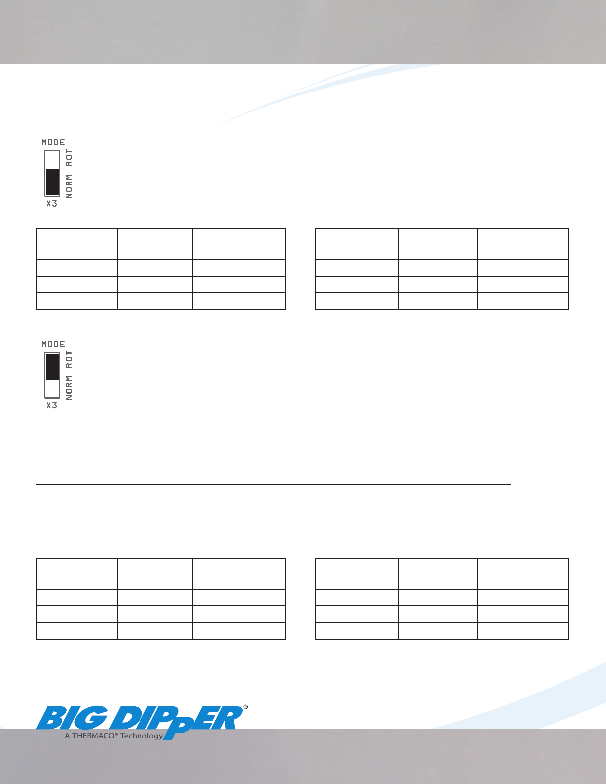
Skim Operation Settings
There are two separate options for timer operation in the 40000 Series Big Dipper. Settings are enabled
by moving the jumper to the correct position on the jumper block marked MODE.
Normal Time-Based Operation
IS and AST Big Dippers ship in Normal Timer Operation which includes both Default and
Extreme Skim Modes with the jumper on the lower two pins closest to “NORM” on the jumper
block.
Default Mode Extreme Mode**
Button
Selected Skim Time Delay Between
Skims*
Button
Selected Skim Time Delay Between
Skims*
Light (I) 15 Minutes 76 Hours Light (I) 90 Minutes 19 Hours
Moderate (II) 30 Minutes 19 Hours Moderate (II) 120 Minutes 19 Hours
Heavy (III) 60 Minutes 19 Hours Heavy (III) 120 Minutes 9.5 Hours
Rotisserie/Thermistor Operation
Big Dipper Models shipped with a Supplemental Water Supply (SWS) for use with Rotisseries
and Combi-Ovens are preset in Rotisserie Mode with the jumper on the upper two pins
closest to “ROT” on the jumper block. When this jumper position is selected, normal, time-
based skimming is discontinued and operation is controlled by rises in temperature. When
the temperature increases by 15º F or more, the skim cycle is immediately initiated. The skim time is
determined by the mode selected and operates for the duration designated in the table below. Toggling
between default and extreme modes is achieved by the same method described previously.
If no temperature change occurs during the setting’s maximum delay between skims (see tables
below), the Big Dipper reverts to operating in standby mode and operates at the preset skim frequency.
If a Supplemental Water Supply (SWS) is used in conjunction with this mode, the SWS will operate
whenever the motor is engaged.
Default Mode Extreme Mode**
Button
Selected Skim Time Delay Between
Skims*
Button
Selected Skim Time Delay Between
Skims*
Light (I) 30 Minutes 6 Hours Light (I) 30 Minutes 2 Hours
Moderate (II) 60 Minutes 6 Hours Moderate (II) 60 Minutes 2 Hours
Heavy (III) 90 Minutes 6 Hours Heavy (III) 90 Minutes 2 Hours
* Delay between Skims is the time from the start of the 1st skim to the start of the next skim. This is the maximum amount of time the unit will go between
skims in Rotisserie Operation if a temperature change of 15º F or greater does not occur.
**Access Extreme Mode by interrupting power from unit (disengage safety switch or unplug from electrical socket) and then holding down Heavy (III)
Button while resuming power supply to unit. To return to Default Mode, interrupt power and hold down Light (I) Button while supplying power.
Board Settings for 40000 Series Big Dipper

Copyright 2014 • Big Dipper® Thermaco, Inc®. • 5info@thermaco.com • www.big-dipper.com • 1-800-633-4204
Board Settings Quick Reference Guide
IS Unit Jumper Settings
At right are standard jumper settings for the Printed Circuit Board on the
Internal Strainer Line of Big Dipper Units.
HEATER: Jumper on Position B for Silmutaneous Heat
AST: N/A
MODE (Skim Operation): Jumper on NORM for Normal Time-Based Operation
W-250-AST Jumper Settings
At right are standard jumper settings for the Printed Circuit Board on the
W-250-AST.
HEATER: Jumper on Position B for Silmutaneous Heat
AST: Jumper on upper two pins; AST function operates 10 seconds every 24 hours
MODE (Skim Operation): Jumper on NORM for Normal Time-Based Operation
W-750-AST and W-1250-AST Jumper Settings
At right are standard jumper settings for the Printed Circuit Board on the
W-750-AST and W-1250-AST.
HEATER: Jumper on Position B for Silmutaneous Heat
AST: Jumper on lower two pins; AST function operates 15 seconds every 2 hours
MODE (Skim Operation): Jumper on NORM for Normal Time-Based Operation
Rotisserie Operation Jumper Settings (for use with SWS)
At right are standard jumper settings for the Printed Circuit Board on Big
Dipper units shipped with Supplemental Water Supplies for use with
Rotisseries or Combi-Ovens.
HEATER: Jumper on Position B for Silmutaneous Heat
AST: N/A
MODE (Skim Operation): Jumper on ROT for Rotisserie/Thermistor Operation

6 • info@thermaco.com • www.big-dipper.com • 1-800-633-4204 Copyright 2014 • Big Dipper® Thermaco, Inc®
Push Button Interface
Three separate silicone momentary contact buttons for
Light (I), Moderate (II), and Heavy (III) skimming modes
and a Start Button for testing and immediate operation.
Built-in LED’s behind buttons indicate mode chosen and
blink during operation.
Startup
**Before applying power to unit, always make sure tank is full of
water**
1. Upon applying power to the unit, all lights will activate
for 1 second.
2. If the (I) Button blinks 4 times, the unit is operating in
Default Mode.
3. If the (III) Button blinks 4 times, the unit is operating in Extreme Mode.
4. The last setting chosen will remain illuminated. See corresponding chart (page 4) to determine skim
time and frequency chosen.
Operation
1. During a skim cycle, the skim setting will remain illuminated.
2. The Start Button will light up during a skim cycle.
Error Codes
In Error Code events, all four lights on the Push Button Interface will ash in one of the following
sequences:
1. 3 Flashes - There is no information coming from the thermistor. Check to ensure the wire is properly
connected to the board and there are no frays in the wires. If wiring is correct, replace thermistor.
2. 4 Flashes - The thermistor is reading an extremely high temperature inside the tank, meaning the
water level inside the unit has dropped below the heater. Check to verify the tank is full of liquid
and cycle power. If error code repeats despite the heater sitting in liquid, replace the thermistor.
3. 5 Flashes - There is a voltage out of range on the printed circuit board. Verify that all wiring
connections are secure and there are no frayed wires inside the Center Module. If wiring is correct,
printed circuit board (PCB-2) will need to be replaced.
Light Codes for 40000 Series Big Dipper
VOICE 336-629-4651 FAX 336-626-5739
PO BOX 2548, ASHEBORO, NC 27203
646 GREENSBORO STREET
DESTROY THIS DRAWING, IT IS THE SOLE PROPERTY OF THERMACO, INC. AND MUST BE RETURNED UPON REQUEST.
OF THIS DRAWING DOES CONSTITUTE AN IMPLIED AGREEMENT BETWEEN THERMACO, INC. AND THE HOLDER OF THIS DRAWING. DO NOT
WRITTEN CONSENT FROM THERMACO, INC. POSSESSION OF THIS DRAWING DOES NOT CONSTITUTE THE RIGHT TO MANUFACTURE. POSSESSION
THIS DRAWING CONTAINS PROPRIETARY AND PATENTED MATERIAL. THIS DRAWING MAY NOT BE REPRODUCED IN WHOLE OR IN PART WITHOUT
.XXX +/- 0.015
.XX +/- 0.03
Decimals
+/-1°
Angular
Tolerances
Dimensions are in inches
Unless otherwise specified
MATERIAL (UNLESS NOTED)
FINISH (UNLESS NOTED) PART NO.
CHECKED
ENGINEERING
DRAWN DATE
A
THIRD ANGLE PROJECTION
RELEASE DATE
REVISIONS
ZONE REV DESCRIPTION DATE APPROVED
SCALE SHEET OF
SIZE REV. NO. DWG NO.
Heavy Setting (III):
Use for Steakhouses,
Buffets, Heavy Grease
producing sites.
Start Button: Press
to begin a cycle early
or to test operation..
Light Setting (I):
Use for small cafes,
coffee and ice cream
shops.
Moderate Setting (II):
Use for Quick and Full-
Service restaurants.
Table of contents
Other THERMA Ventilation Hood manuals

Popular Ventilation Hood manuals by other brands

Kleenmaid
Kleenmaid KCRHSO6010 Instructions for use and warranty details

Bosch
Bosch DFS097K51 User manual and assembly instructions

Zanussi
Zanussi ZFG215S user manual

Küppersbusch
Küppersbusch KD 9550 Instruction booklet

Faber
Faber CRISTAL Installation instruction

Multikomplex
Multikomplex SLT966-EM Installation, Use and Maintenance Instruction


