Thermasis Cortina 12 S Instruction Manual

CORTİNA
- S -
INSTALLATION / USER
MANUAL

Cortina S manuel Ver.01
2
1 DEAR CUSTOMER
Thank you for purchasing Cortina wood pellet boiler.
This instruction manual is intended to help you install and operate the product
safely, properlyand economically.
Please read this instruction manual right through and take note of the
safetywarnings.Keep all documentation supplied with this unit in a safe place for
future reference.
Do not touch or interfere any part of the product other than those allowed.
During installation and/or first start up the service engineer must carry out
thefollowing work.
The installation has to be performed by a qualified installer.
Please contact your authorised dealer if you have any questions.
For efficient and low-emission operation of your heating system, only use the
fuels specified in this instruction manual. Only then can efficient, low-emission,
and trouble-free operation of your heating system be guaranteed.
Carry out maintenance and cleaning work recommended on your heating system
at regular intervals. Details can be found later in the instruction manual. By doing
this, you will not only be ensuring the operational reliability of the heating
system but also its efficient and low-emission operation.
• Your pellet boiler will automatically adjust its output between 30 to 100% of the
boiler’s rated power. Your heating system may have a lower or higher heat
demand than the boiler can deliver, for this reason we recommend a buffer tank
is installed. The buffer tank ensures operational reliability of the appliance and
improves heating response and energy saving. This ensures efficient and low-
emission operation of your boiler.

Cortina S manuel Ver.01
3
2 INTRODUCTION AND DELIVERY
Cortina is a welded steel boiler designed for automatic burning of wood pellets to be used in hot
water heating installations. Therefore, it can not be used for direct sanitary water supply.
Main features and advantages of Cortina wood pellet boiler:
Very compact dimensions thanks to its unique vertical design
Integrated fuel container
Adjustable boiler output
High efficiency and nature-friendly flue gas emissions
Automatic ignition of wood pellets
Automatic feeding
Stainless steel burning pot and fuel feeder
PID control ensures a stable output where it is adjusted
Exhaust fan speed modulation and speed control via encoder
User friendly electronic control board
Manual and simple burner cleaning
Manually activated smoke tube cleaning
Fuel level monitoring window
Flue thermostat
Room thermostat option
Fire protection
Buffer tank
Your boiler is delivered in one single package secured on a wooden pallet, with all accessories and
external cabinet fit before leaving factory. You can reach the cleaning equipment under the ash
cleaning cover of boiler.

Cortina S manuel Ver.01
4
Main parts that are related to operation of boiler:
1 Fuel loading door 6 Flame inspection window
2 User interface (control panel) 7 Burning pot cleaning cover
3 Smoke tube cleaning lever 8 Ash cleaning cover
4 Fuel level monitoring window 9 Service / electronic board cover
5 Cleaning cover shield

Cortina S manuel Ver.01
5
3 SAFETY WARNINGS
3.1 Basic safety instructions
• Never get yourself into danger; give own safety the utmost priority.
• Keep children away from the boiler room and fuel storage room.
• Observe all instructions related to operation, maintenance, servicing and cleaning.
• The pellet heating system may only be installed and started up for the first time by an
authorised installer. Professionalinstallation and start up are essential for safe and economical
operation.
• Never make any changes to the heating system or flue gas system.
• Never close or remove safety valves.
3.2 Warning signs
DANGER
Risk of poisoning
Make sure that the pellet boiler is supplied with sufficient combustion air.
The openings in the combustion air inlet must never be partially or
completely closed.
Ventilation systems, central vacuum cleaning systems, extractor fans, air
conditioning systems, flue gas blowers, dryers or similar equipment must
never be allowed to draw air from the boiler room and cause a drop in
pressure.
The boiler must be connected tight to the chimney using a flue gas tube.
Clean the chimney and the flue gas tube at regular intervals.
The boiler room and pellet storage room must be sufficientlysupplied with
air and ventilated.
DANGER
Risk of electric shock
Switch off the system before performing work on the boiler.
THIS APPLIANCE MUST BE EARTHED !
Electrical installation of this boiler must be completed in accordance with
mandatory regulations, and codes of practice regarding the instructions
given in this manual by authorized installator.
DANGER
Risk of explosion
• Never burn petrol, diesel, engine oil or other explosive materials in the boiler
or storage room
• Never use liquids or chemicals to ignite the pellets.
• Switch off the heating system before filling the storage room.

Cortina S manuel Ver.01
6
DANGER
Risk of fire
• Do not store any flammable materials in the boiler room.
• Do not hang out any washing in the boiler room.
• Always keep all boiler doors closed
• Store the pellets in another room, or leave a minimum distance of 80 cm
between the boiler and the pellet pile.
WARNING
Risk of burns
• Do not touch the flue spigot or the flue gas tube.
• Do not reach into the ash chamber.
• Do not remove service cover due to volteged components under the cover
• Do not clean the boiler until it has been allowed to cool down.
CAUTION
Risk of cut injuries due to sharp edges.
• Use gloves for performing all work on the boiler.
NOTICE
Damage to property
• Heat the Pellematic pellet heating system using pellets that comply with the
specifications below
Damage to property
• Do not use the heating system if it, or any of its components, come into
contact with water.
• If water damage occurs, have the heating system checked by your authorised
service stuff or approved technicians, and have any damaged parts replaced
in case needed.
3.3 What to do in an emergency
What to do in the event of a fire
• Switch off the heating system.
• Call the fire brigade
• Use approved fire extinguishers.
What to do if you smell smoke
• Switch off the heating system.
• Close the doors leading to living areas.
• Ventilate the boiler room.
Cortina S manuel Ver.01
7
4 TECHNICAL DATA

Cortina S manuel Ver.01
8
Models
Cortina 12
S
Cortina 18
S
Cortina 24
S
Cortina 32
S
Cortina 40
S
Fuel specifications
Wood pellets size 6 mm
Fuel parameters shall comply to EN 14961
Boiler class
Class 5 acc to EN 303/5
Operation mode
With fan at flue exhaust working
under pressure at
flue gas outlet
Maximum power input
kW
15,6
19,2
24,8
32,6
42
Maximum power output
kW
14,2
17,1
22,1
29,6
37,2
Minimum power output
kW
4,5
5,2
6,6
8,9
11,2
Efficiency at max output
%
0,91
0,89
0,89
0,91
0,89
Efficiency at min output
%
0,89
0,86
0,85
0,87
0,87
Flue gas temperature at max
power °C
116,4 155 150 140 120
Flue gas temperature at min
power °C
84,6 125 120 110 100
New weight
kg
160
165
185
225
250
Water content
lt
44
40
45
70
76
Fuel container capacity
kg
45
55
85
95
lt
80
100
155
180
Fuel filling openning size
mmxmm
450x290
436x258
436x328
536x328
Combustion period
h
12
Minimum return temparature
°C
40 (With non
-
condensing working conditions)
CO emission
EN 303/5 Class5
Flue gas mass flow
g/s
16
21
25
30
Required draft at chimney
Pa
8
-
10
10
-
12
12
-
15
Temperature control range
°C
45
-
80
Max operating temperature
°C
80
Max operating pressure
bar
3
Water flow/return connections
D
D
D
G
1" (male)
Filling/draining connection
R
½" (male)
Burner design
Stainless steel cylindrical pot
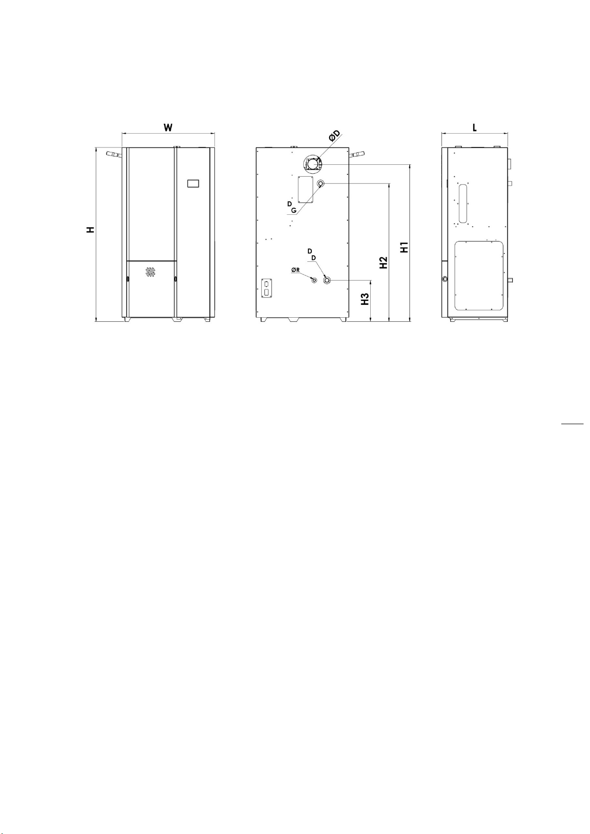
External dimensions
H
mm
1365
1490
1620
1670
W
mm
730
850
900
H1
mm
1195
1235
1360
1490
1540
H2
mm
1050
1085
1210
1340
1390
H3
mm
300
325
360
L
mm
520
570
620
D
mm
127
Electrical supply
230V / 50Hz
Power consuption
(fan+feeder motor) W
75 71
Power consuption (igniter)
W
165
5 INSTALLATION

Cortina S manuel Ver.01
9
5.1 Handling the product
Cortina is a heavy product, and care should be taken when carrying the boiler to the room where it
is going to be installed. The total weight of each boiler is indicated in technical data section.
Carrying equipment of the product must be of enough capacity to support that weight. To avoid
damage during transport, boiler should be moved with forklift or transpalet. Use the transport
feets on the wooden pallets.
NOTICE
Damage to property
• Do not use hard and sharp objects while removing the package around the
boiler to prevent damage of the painted jackets.
5.2 Room selection
Cortina series boilers must be installed in an individual boiler room particularly organized for
heating. The boiler room should be of enough volume for installation, firing, and maintenance of
the boiler. There should be enough space from the wall for easy removing the geared motor and
the shaft for service intervention. For appropriate dimensions look into “clearances around boiler”
section.
There should be enough fresh air circulation for combustion, the chimney design must ensure an
adequate draught for related boiler type, and must comply with construction criteria given further
in this manual and in mandatory regulations. Your boiler must never be installed in open spaces or
balconies, in spaces occupied by people like kitchen, living room, bathroom and bedroom, in
spaces where there are explosive and combustible materials.
The boiler room should have air ventilation holes through outside to let fresh air in. One air
ventilation hole must be built maximum 40 cm below the level of room ceiling; the other must be
built maximum 50 cm above the floor level. These ventilation holes should always be kept open.
The upper hole should be at least 40x40 cm in size, the lower hole at least 30x30 cm.
All hydraulic and electrical circuits must be arranged by authorized staff in accordance with
mandatory regulations specified by legal organizations.
Pellets should be stored by keeping minimum 800 mm distance from the boiler. We recommend
you to keep the solid fuel in another room.
Cortina boiler should be installed on a concrete plinth made of a fireproof material. For minimum
sizes of the plinth following table should be referred:
Model Cortina 12/18 / 24 Cortina 32 / 40
Plinth height (mm) 50
Plinth width (mm) 800 900

Cortina S manuel Ver.01
10
Plinth length (mm) 600 650
5.3Clearances around boiler
At least the following clearances should be achieved around the boiler. When the boiler is placed
to the boiler room enough distance should be left for easy fuel loading to bunker, easy removing
the geared motor and auger and easy servicing.
5.4 Circulation pump
We recommend building a forced water circulation system accompanied with a sufficient pump.
Refer to the system diagrams given further in this manual to find the right position of thepump
within the hydraulic circuit.
Your boiler automatically switches the pump on and off according the program stored in its PCB.
That is why circulation pump must be driven by the control panel. Wiring to the pump is supplied
at the back of the boiler.
5.5 Rules for hydraulic circuit
Cortina boiler can be installed in a pressurized heating circuit with addition of a closed expension
tank in respect with one of the following schemes. If heat demand of building differs from the
nominal capacity of boiler, we recommend a buffer tank between primary circuit and heating
installation. Hydraulic circuit should have at least the equipments listed below:
Circuit without buffer tank:

Cortina S manuel Ver.01
11
Circuit with buffer tank
1
Primary circuit pump
6
Safety valve
11
Heating circuit pump
2
Globe valves
(open)
7
Manometer
12
Buffer tank
3
Globe valves (closed)
8
Radiator
13
Cortina
boiler
4
Check valve
9
Expansion tank
S1
Boiler probe
5
Strainer
10
Air relief valve
S2
Buffer probe
We recommend a buffer storage tank capacity of 25 to 50 litres per kW boiler output.

Cortina S manuel Ver.01
12
For correct sizing of closed expansion tank, refer to calculations supplied by the manufacturer.
Nevertheless, the volume of closed expansion tank should not be less than:
12 liters for Cortina 12
12 liters for Cortina 18
18 liters for Cortina 24
24 liters for Cortina 32
30 liters for Cortina 40
NOTICE
Safety of heating circuitg
• Install a ½” safety valve with a maximum relief pressure of 3 bars.
• Install a manometer to follow and check water pressure in the system. When
water is cold, system pressure should be set at 1 – 1,5 bars.
WARNING
Risk of corrosion on boiler and heating circuit
• Your boiler is quite a strong design against corrosion. However, all metal
surfaces in whole heating circuit should be protected against corrosion like
piping and radiators. The oxygen in heating water will cause rust and then
material loss on iron-based metal surfaces by means of oxidation.
• During the first water make-up, oxygen must be fully discharged from the
system. Generally, oxidation will not be a problem, if all measures are taken
into account during first water make-up. Oxidation will take place because of
fresh water addition to the system during operation of the boiler. Leak
points in a system will cause oxygen to be absorbed inside the heating water.
For this reason, minimum water pressure in a pressurized heating circuit
must be above atmospheric pressure. Besides, pressure levelshould always
be checked periodically.
CAUTION
For new installations
• System should be sized and designed accordingly, in order to minimize fresh
water addition. Make sure that no part of the system is made of material
that is permeable to gases. The original system filling water and any topping-
up water must always be filtered (using synthetic or metal mesh filters with a
filtration rating of no less than 50 microns) to prevent sludge from forming
and triggering deposit induced corrosion. Minimum water pressure in a
pressurized heating circuit must always be kept above atmospheric pressure

Cortina S manuel Ver.01
13
CAUTION
For a new boiler installed on an old heating circuit
• In old systems used for a long time, a protective coating (black magnetite)
has been built on all metal surfaces contact with water. This coating protects
the system agains further corrosion. When a mew boiler is installed in such
an old system, new parts with clean metal surfaces, particularly boiler
surfaces will inevitably become sacrificial anode for the entire heating
system, in other words, they come in the first place where corrosion starts.
That is why, following precautions should be added to those given above, for
a new boiler in an old system:
• If the old system has an open expension tank, this may be converted to
pressurized system with all necessary safety measures.
• The old system must be fully washed up from all substitutes and particules
contained on the surfaces.
• An air separator with manual vent should be installed at the heighest level of
the circuit.
5.6 Chimney connection
Cortina boiler must be connected to an individual
chimney that will provide at least the minimum
draught given in the technical data of boiler. The flue
duct between the boiler and the chimney should be
insulated using a glass wool material. The flue duct to
chimney and chimney must be made of steel or an
equivalent material that can beresisting at
temperatures around 400oC. All connections on the
flue system must be sealed in order to perform a
good combustion and efficiency. The flue duct must
be connected to the chimney using the shortest way
and in accordance with the dimensions given in the
following scheme. Horizontal connections and
equipment that will increase the pressure loss such as
elbows should be avoided.
At the lowest level of chimney, there should be a
cleaning cover which is made of steel, and sealed for
any leakage. The length of flue duct between the
boiler and the chimney should not exceed ¼ height of
chimney. The size of flue duct and chimney should
not be less than the size of the boiler flue gas outlet
connection. For the total height and the minimum
internal diameter of the chimney, following diagram
should be referred in respect with boiler output
power, if otherwise stated in mandatory regulations.

Cortina S manuel Ver.01
14
The size of flue canal and chimney should not be less than the size of the boiler flue gas outlet
connection. For the total height and the minimum internal diameter of the chimney, following
diagram should be referred in respect with boiler output power, if otherwise stated in mandatory
regulations.
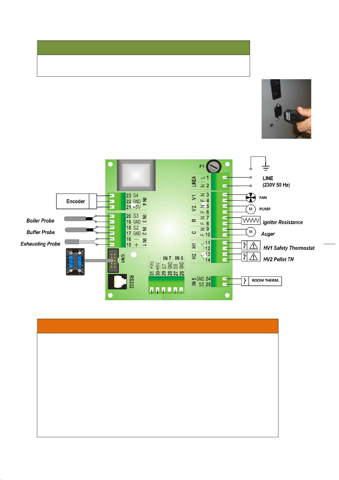
5.7 Electrical installation
The boiler is fed with 230 V. A regulator must be used in installations where the power supply is
below 205 V or above 230 V.
WARNING
All electrical installations must be carried out by authorized persons in accordance
with mandatory regulations and codes of practice. Only qualified personnel may
open the control panel on the boiler. Any interference with the wiring in the
control panel will invalidate the warranty.
Connecting the power cord
Control panel should be connected to a wall plug with an efficient ground
system, which is placed not far more than 50 cm. to boiler with a circuit
breaker which has at least 3 mm gap between contacts. Use the power cord
supplied with the boiler.
Cortina S manuel Ver.01
15
CAUTION
If the supply cord is damaged, it must be replaced by a special cord or
assembly available from the manufacturer or its service agent.
Connecting the pump
Use the socket given attached with the boiler to make the pump connection.
Incorrect core termination can cause severe injuries and damage to the
equipment. Take care not to interchange wires "L1" and "N". Recommended
connecting cable H05VV-F3G 0.50 mm2
Boiler Control Panel Electrical Schematic
WARNING
• Before doing any work on the boiler related with electricity, ensure that the
power supply cable is disconnected from the network electricity or turn off
the main switch located at the back of the boiler
• Sensor wires, sensors and keyboard wires must be mounted so that they
cannot be accessed without disassembling the combustion device.
• Earth connection must be connected to the controller and to the
metal part of the combustion device.
• Some of the wires carry dangerous voltages. Disconnect the controller
from the mains power supply prior to any service or mounting
operation.
• Do not exchange high voltage and low voltage connectors during the
mounting of the controller.

Cortina S manuel Ver.01
16
6 FUELS
Wood pellets are natural wood (dried sawdust or waste from machining) that has been formed
into pellets under highpressure. They have a very low moisture content and very high calorific
value.
6.1 Pellet quality
We recommend using pellets certified on new normative with EN Plus-A1 grade. If this quality
could not be found, the pellets must then comlpy with one of normatives given in the following
table:
Parameter
Standards
Unit
ENplus-A1
Specification
CEN/TS
14961-2
Grade A1
Old
ÖNORM
M1735
DIN+
(DIN
51731)
Moisture (M)
≤10.0
≤10.0
≤12.0
≤12.0
w
-
%
Ash, 550°C (A)
≤0.7
w
-
%
Ash, 815°C
≤0.7
≤0.5
≤0.5
w
-
%
Durability (DU)
≥97.5
≥97.5
≥97.7
w
-
%
Fines (F)
2
≤1.0
≤1.0
≤1.0
≤1.0
w
-
%
Additives
≤2.0
≤2.0
≤2.0
≤2.0
w
-
%
Net calorific value (Q)
≥4.6 & ≤5.3
≥4.6
≥5.0
≥5.0
kWh/kg
Net calorific value (Q)
≥16.5 & ≤19.0
≥16.5
≥18.0
≥18.0
MJ/kg
Bulk density (BD)
≥600
≥600
kg/m
3
6.2 Pellet size
Suitable pellet size for Cortina boiler:
Diameter 6 mm; maximum lentgh 40 mm.
6.2 Storing the pellets
1. Pellets are to be stored in a place where they are kept dry all year.
2. Legislation in your country must be observed regarding building specifications for storage
rooms.
WARNING
Damage to property
• Use of unproper pellets in Cortina boiler can block air entrance to burner,
can cause damage on boiler and chimney. Use of these kind fuels will make
warranty of the boiler invalid.

Cortina S manuel Ver.01
17
7 OPERATION
Control Panel: Use and Functions
Led
P1
P2
P3
P4
START
STOP
SET
TA
OFF
ESC
D1 D2
D3D4
L1
L3
L4
L5
L6
L7
L8
Led Fix Blinking
L1 Stabilization phase Ignition Start phase
L3 Burner OFF Extinguishing phase
L4 Work phase Modulation/Standby phase
L5 Auger ON -
L6 Igniter Resistance ON -
L7 - External Thermostat open
L8 Pump -
Display
Display Fix Blinking
D1 Work Combustion Power
Set
D2 Boiler Thermostat Set Combustion Power Change
D3 Boiler Temperature Boiler Thermostat Change
D4
I indicates the Pellet
recipe 1
II indicates the Pellet
recipe 2
-
Buttons
Button Click [P click] Long Pressure [P long]
P1 Display other data / Esc Pellet recipe selection
P2 Set in to the Menu function Burner Start / Stop
P3 Thermostat Setting/ Increasing Value / Scroll
Menu Pellet Loading Correction
P4 Combustion Power Setting/Decreasing
Value/Scroll Menu Manual Pellet Loading
Alarms
Safety Thermostat (boiler) HV1: always signalled
Block
Safety Thermostat (pellet) HV2: always signalled
Block
Extinguishing for Lack of Flame
Block
Extinguishing for Water over Temperature
Block
Extinguishing for Exhaust gas over Temperature
Block
Encoder Error: No Encoder Signal
Block
Encoder Error: Combustion Fan regulation failed Block
Failed Ignition
Block
Lack of fuel
Block
Anomaly in probe control during Check Up phase
The reset of the BLOCK Condition is done by the Long Pressure of the button P2

Cortina S manuel Ver.01
18
User Menu - Settings
Fuel or Recipe Selection
Through a long pushing of the button P1 is changed the type of receipe.
The display D4 shows the selected recipe (I=Recipe 1; II= Recipe 2)
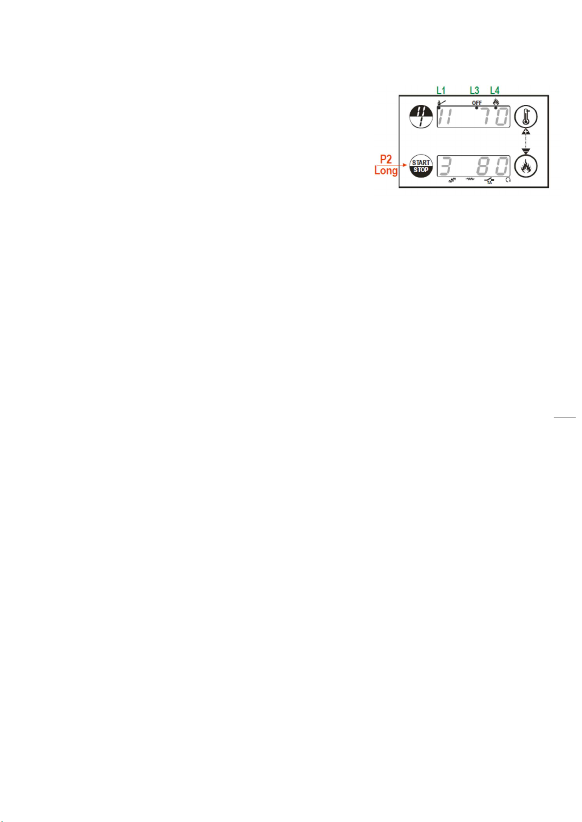
Ignition/Exstinguishing
The Ignition and Extinguishing are activated with a long pushing of the button P2
The Ignition is signalled by the first blinking than fix led L1
The Work state is signalled by the fix led L4
The Modulation state is signalled by the blinking L4
The Extinguishing is signalled by the blinking led L3
The Extinguishing finished = OFF state is signalled by the fix led L3
Combustion Power Setting
Click button P4: the display D1 blinks
Trough the click of the buttons P4 (increasing)or P3 (decreasing) the power is changed
according to the values available
Ex.: 1 – 2 – 3 – 4 – 5 – A (A= Automatic Combustion)
After 5 seconds the new value is memorised and the display shows as normal
Work Thermostat Setting
Click button P3: the display D2 blinks
Trough the click of the buttons P4 (increasing)or P3 (decreasing) the value of the thermostat
is changed.
After 5 seconds the new value is memorised and the display shows as normal
Manual Pellet Loading
The long pressure of button P4 activates the Pellet Manual Loading with activation of Auger
in continuous way.
The bottom display shows LoAd and the upper display shows the elapsed loading time. To
stop the loading push any button. The loading stops automatically after 300 seconds
Pellet Loading Correction
The activation is with a long pushing of the button P3
The bottom display shows PELL, the upper display shows the blinking value
With buttons P3 / P4 the blinking value increases or decreases
The values are between the range– 7 ÷ 7.The default value is ‘0’
After 5 seconds the new value is memorised and the display shows as normal
Display
With a click sequence of P1
tP= Buffer Probe Temperature (if present)
UF= Combustion Fan Speed [RPM/Volt]
tF= Exhaust temperature [°C]
bA3 + Product Code
00.00

Cortina S manuel Ver.01
19
7.1 Supply Voltage Lack Management
In case of power failure, the system saves the most important functioning data. When the control
board is supplied again, the system evaluates the saved data and if the Burner were ON in the
phases Ignition, Normal, Modulation, Standby, the system goes in Recover Ignition.
In case of functioning state of OFF or Block, the system goes back to the previous state.
7.2 START-UP
Loading the pellets
Open the fuel loading door, and fill the container with pellets. Do not put any other fuels than
specified wood pellets, or any other material. Then close fuel loading door. Observe the fuel level
in the container each day through the inspection window at the right hand side of boiler.
At the first loading the feed screw may be empty. So use the manual pellet loading function (look:
“usermenu-settings”) to supply some pellets to the feed screw.
Switch ON the boiler
Check the boiler to be in “OFF” position (fixed led L3).
Switch ON the boiler with a long pushing of the button P2.
Led status when the boiler is ON:
1. The Ignition is signalled by the first blinking than fix
led L1
2. The Work state is signalled by the fix led L4
3. The Modulation state is signalled by the blinking L4
If the ignition is not succeed during the predefined time (time out) the controller will turned OFF
and the error message “Err12” will be displayed.
WARNING
• An odour of the paint can be felt while the boiler fired up for the first
time.
• Do not open the combustion chamber door during operation.
• Never fill the burner pot with pellets by hand. Excessive combustion
material in the burner pot means that the pellets will not be ignited
optimally.
Cortina S manuel Ver.01
20
Switch OFF the boiler
Switch OFF the boiler with a long pushing of the button P2.
Led status when the boiler is switched OFF:
1. The Extinguishing is signalled by the blinking led L3
2. The Extinguishing finished = OFF state is signalled by
the fix led L3
When the boiler is switched OFF the fan continues running until the flue gas temperature falls
below the set trash hold and then the fan is turned off.
7.3 Operation Phases
Check Up
This stage allows for the cleaning of the boiler and burner before the ignition phase.
-The exhaust fan on the burner run at full power to eliminate any dust or smoke (in the event of a
hot restart) from the boiler.
-All the system sensors are checked for correct connections.
Pre-Heating
This stage brings the ignition element to the correct temperature before loading the burner with
pellets.
Pre-Load
A pre-defined starting dose of pellets is given into the burner by the auger.
Variable Ignition
This stage starts the ignition process.
-The heat from the ignition element is directed at the pellets by the fan which runs at a relatively
slow speed.
-At intervals the auger introduces more pellets once the flame has begun to establish.
-The flue gas temperature probe measures the temperature in the flue.
-At the end of this stage if the flue gas temperature is over a pre-defined temperature the process
continues to the next stage (Stabilisation)
-If this variable are not satisfied then this stage continues for another minutes (second ignition
attempt) and if the variable has not reached its value by the end of the second attempt,
EXTINGUISHING will occur and an Er12 (Failed Ignition) will be displayed on the screen.
Stabilisation
This stage develops the flame even further before allowing the system to enter RUN mode.
This manual suits for next models
5
Table of contents
Other Thermasis Boiler manuals


Popular Boiler manuals by other brands


Italtherm
Italtherm 18 K Instruction

HydroTherm
HydroTherm HV-75 User's information manual

Buderus
Buderus Logamax plus GB142-24 Instruction

Ariston
Ariston microGENUS 23 MFFI Servicing instructions

Bosch
Bosch GWH C 920 ES instruction manual

EUROPEAN FINISHING EQUIPMENT
EUROPEAN FINISHING EQUIPMENT EVG - 24 Series Operating/safety instructions