THERMO 2000 TURBOMAX 109 User manual

TURBOMAX
®
Instantaneous Indirect Water Heater
USE & CARE MANUAL
WITH INSTALLATION INSTRUCTIONS FOR THE CONTRACTOR
Your TURBOMAX
®
Instantaneous Indirect Water Heater has been carefully assembled and
factory tested to provide years of trouble-free service. In order to insure the service intended,
the following information is provided to enable proper installation, operation, safety
precautions and maintenance of this product.
It is imperative that all persons who are expected to install, operate or adjust this water heater
read the instructions carefully so that they may understand how to do so.
Any questions regarding the operation, maintenance, service or warranty of this water heater
should be directed to the entity from whom it was purchased.
When all installation steps have been completed, replace this installation manual in its original
envelope, and keep in a safe place for future reference.
Note: Copyright 2005. Thermo 2000 Inc. All rights reserved. Turbomax® is a registered trademark of Thermo 2000 Inc.
Thermo 2000 reserves the right to modify at any time and without notice colors, components, materials, specifications or
model described in or shown in this document.
Revision : July 2014
THERMO 2000 INC.

TURBOMAX Use and Care Manual with Installation Instructions July 2014 Page
2
TURBOMAX
®
Specifications
The Turbomax indirect water has an internal copper domestic
heat exchanger made of multiple helical copper tubes
operating in parallel with a 150 psi.(200psi on ASME models
109A) maximum operating pressure rating.
All copper
components and assembly meet the low lead
requirements for potable plumbing products and adhere
to the NSF 61 standard (International Standard Drinking
Water Systems Components Health Effects
. The hot
water heater has a patented steel injector through which the
boiler water fluid enters the top side of the tank and a steel
collector through which the boiler water fluid exits at the bottom
of the tank. The tank is be made of high grade carbon steel.
All the steel joints are welded by the MIG/Argon gas process. It
has a maximum operating pressure of 150psi (200psi on
ASME model 109A). The tank is wrapped with a fiberglass
insulation jacket limiting the tank heat loss to less than ½°F per
hour. The outer steel jacket is painted with baked epoxy. The
water heater has a temperature controller (aquastat) that
makes contact when the temperature falls below the tank water
temperature set point minus an adjustable differential (10 to
40F)and breaks contact when the temperature rises over the
set point (95 to 195F). The tank has a ¾” drain ball valve
made of brass, which have a maximum working pressure of
200 psi. 3 adjustable feet support the water heater for leveling.
The hot water heater is shipped from the factory with an ASME
rated pressure relief valve set at 30psi (50 psi. on model 109 ,
65A&109A), a temperature & pressure gage (except #23, 33)
and an automatic air vent. The water heater is backed by a 15-
year warranty on residential applications and 10 years on
commercial applications (consult the terms of the warranty
included at the end of this manual).
SPECIFICATION
Model Tank
Volume
Heat transfer
area (sq. ft.)
Max.
DHW
flow *
Utility
connection
oiler
connection
Height Dia-
meter
Shipping
weight
TURBOMAX
®
109 119usgal
.
58.9 ft² 27usgpm 2’’ Sweat M 2’’ PT M 74’’ 29’’ 555 lbs
T
URBOMAX109A
110usgal 58.9 pi² 27usgpm 2-1/2’ Sweat M 2’’- PT M 74’’ 29’’ 755 lbs
TURBOMAX
®
65 72 usgal. 32.7 ft² 15usgpm 1-1/2’ Sweat M 1-1/2’’ PT M 67’’ 24’’ 250 lbs
TURBOMAX 65A 67usgal 32.7 pi² 15usgpm 2’ Sweat M 1-1/2’’ PT M 67’’ 24’’ 425 lbs
TURBOMAX
®
45 48 usgal. 32.7 ft² 15usgpm 1-1/2’’ Sweat M 1-1/4’’ PT M 55’’ 22’’ 235 lbs
TURBOMAX
®
44 48 usgal. 26.2 ft² 12usgpm 1-1/2’’ Sweat M 1-1/4’’ PT M 55’’ 22’’ 210 lbs
TURBOMAX
®
34 36 usgal. 26.2 ft² 12usgpm 1-1/2’’ Sweat M 1-1/4’’ PT M 65“ 18“ 195 lbs
TURBOMAX
®
33 36 usgal. 19.6 ft² 9usgpm 1-1/4’’ Sweat M 1-1/4’’ PT M 65“ 18“ 170 lbs
TURBOMAX
®
24 26 usgal. 26.2 ft² 12usgpm 1-1/2’’ Sweat M 1-1/4’’ PT M 49’’ 18’’ 175 lbs
TURBOMAX 23 26usgal 19.6 f
t2
9usgpm 1-1/4” Sweat M 1-1/4” PT M 49’’ 18’’ 150 lbs
*Occasional operation at higher gpm is acceptable but must be reduced on application where constant hi flow is required .

TURBOMAX Use and Care Manual with Installation Instructions July 2014 Page
3
General Safety Precautions
Be sure to read and understand the entire Use & Care Manual before attempting to install
or operate this water heater. Pay particular attention to the following General Safety
Precautions. Failure to follow these warnings could cause property damage, bodily injury or
death. Should you have any problems understanding the instructions in this manual, STOP,
and get help from a qualified installer or technician.
To meet commercial water use needs, the
aquastat on this water heater is adjustable up to
195°F. However water temperatures over 125°F
can cause severe burns instantly or death from
scalds. 125°F is the preferred starting point for
setting the control to supply general-purpose hot
water.
Safety and energy conservation are factors to be
considered when setting the water temperature
on the aquastat. The most energy efficient
operation will result when the temperature
setting is the lowest that satisfied the needs
consistent with the application.
Maximum water temperature occurs just after
burner or the energy source has shut off. To find
hot water temperature being delivered, turn on a
hot water faucet and place a thermometer in the
hot water stream and read the thermometer.
The following chart details the relationship of
water temperature and time with regard to scald
injury and may be used as a guide in determining
the safest water temperature for your applications.
TIME VS TEMPERATURE
RELATIONSHIPS IN SCALDS
Temperature Time to Produce Serious
Burn
120°F More than 5 minutes
125°F 1-1/2 to 2 minutes
130°F About 30 seconds
135°F About 10 Seconds
140°F Less than 5 seconds
145°F Less than 3 seconds
150°F About 1-1/2 seconds
155°F About 1 second
Table courtesy of Shriners Burn Institute
The temperature of the water in the heater can be
regulated by setting the temperature dial in front of
the aquastat. To comply with safety regulations
the aquastat was set at its lowest setting before
water heater was shipped from the factory.
There is a Hot Water Scald Potential if the
aquastat is set too high. When this water
heater is supplying general purpose hot water
requirements for use by individuals, a
thermostatically controlled mixing valve for
reducing point-of-use water temperature is
recommended to reduce the risk of scald
injury. Contact a licensed plumber or local
plumbing authority for further information.
DANGER
!
!

TURBOMAX Use and Care Manual with Installation Instructions July 2014 Page
4
Introduction
The important safeguards and instructions
appearing in this manual are not meant to
cover all possible conditions and situations
that may occur. It should be understood that
common sense, caution and care are factors,
which cannot be built into every product.
These factors must be supplied by the
person(s) caring for and operating the unit.
LOCAL INSTALLATION REGULATIONS
This water heater must be installed in
accordance with these instructions and must
conform to local, or in the absence of local
codes, with the current edition of the National
Plumbing Code and the National Electric Code.
In any case where instructions in this manual
differ from local or national codes, the local or
national codes take precedence.
DECISIONS REQUIRED BEFORE
INSTALLATION
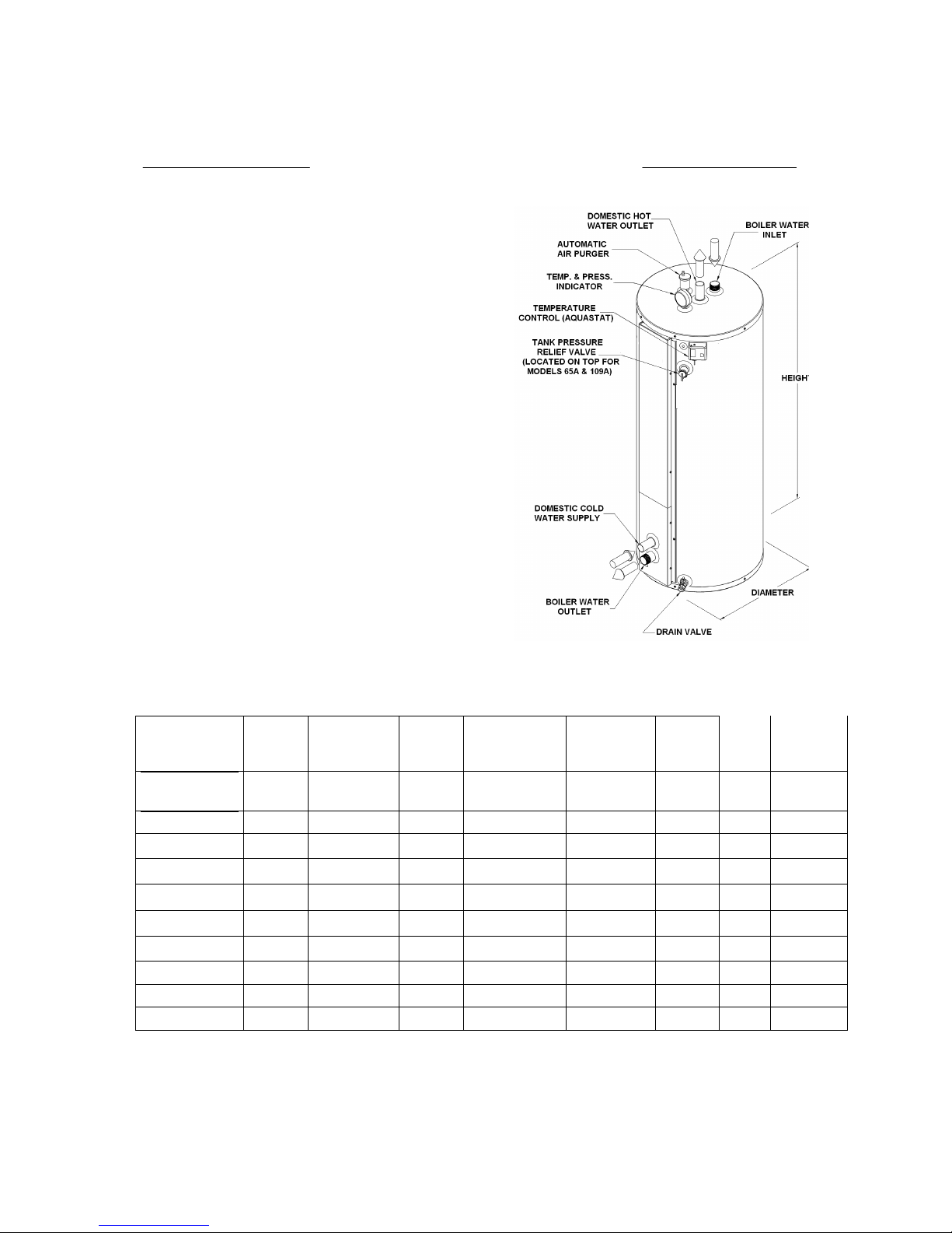
The tank of the Turbomax water heater (boiler
water) is factory shipped with a 30psi (207kPa)
pressure relief valve except on models109,
65ASME and 109ASME where it is factory set at
50psi (344kPa). If the water application requires
a higher operating pressure on the tank and If
local jurisdictions permit it, this valve can be
change by a higher pressure rated valve (max
150psi or 200psi on ASME models). But, on an
installation used to provide hot water for
domestic use, the tank pressure must always
remain lower than the pressure of the domestic
water supply specially on applications where a
potentially toxic heat transfer solution is used
inside the Turbomax tank
In some jurisdictions the boiler’s operating
pressure must be limited to 30 psi (207 kPa) by
a safety relief valve. When a higher operating
pressure level is needed, select a boiler which is
certified to operate at the required pressure.
The boiler’s output rating must be within the
heater’s recommended sizing guide
specifications. Too high an output rating may
cause a boiler short cycling condition.
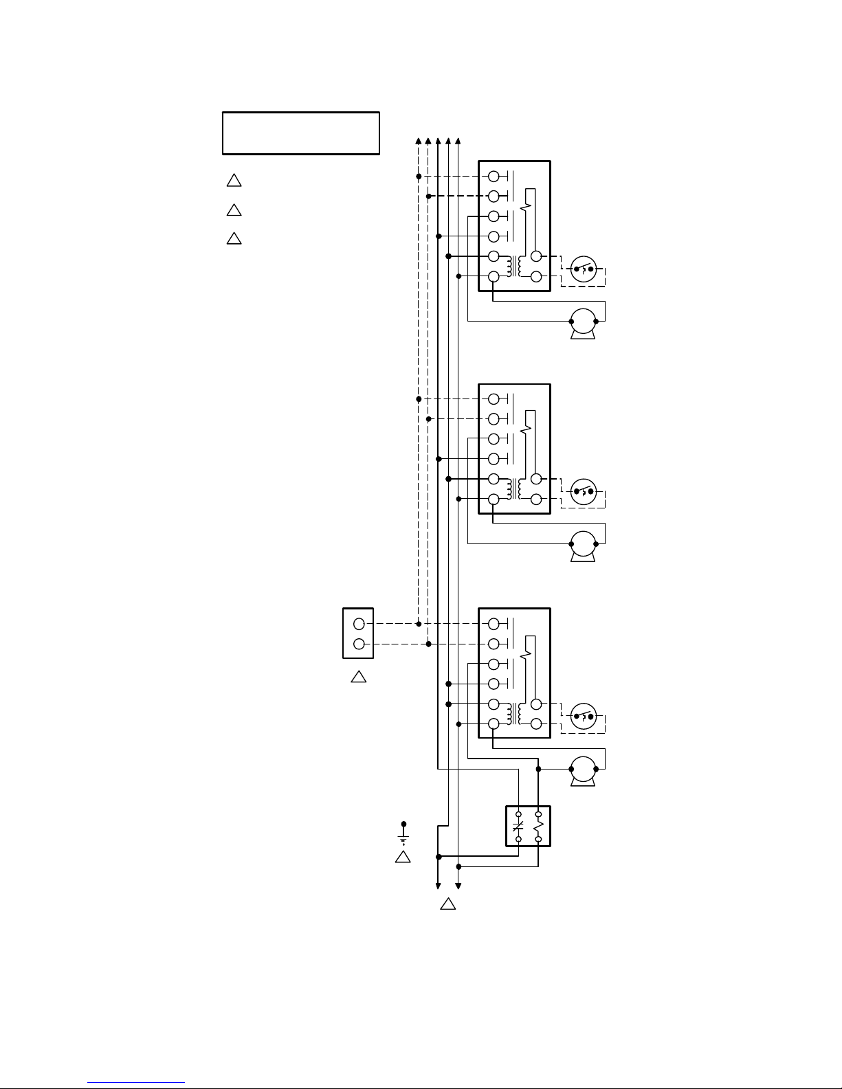
Where the boiler’s output is used to supply
space heating and domestic water heating, two
options are available when wiring the controls.
The first option uses a priority relay. When the
aquastat of the water heater calls for heat, the
relay shuts off the space heating zones, giving
priority to producing domestic hot water. Any
demand for space heating is postponed until the
water heater has reached a preset level. This
delay in supplying the space heating zones is
usually not noticed by those occupying the living
space. The water heater gets adequate hot
water flow from the boiler to maintain the full
rated delivery of domestic hot water.
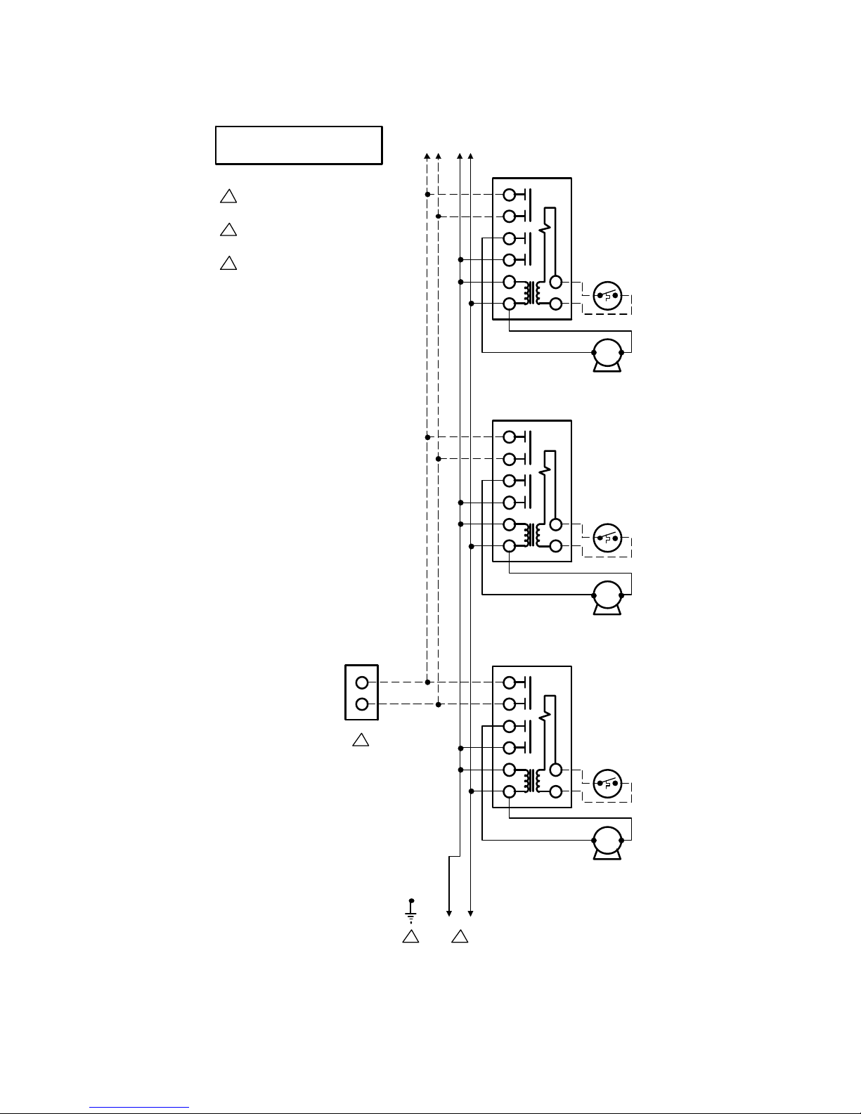
In the second option, the water heater will be
supplied as just another heating zone. This
means that if all space heating zones call for hot
boiler water at the same time, the water heater
may not be supplied with enough hot boiler
water to “recover” adequately. The delivery of
domestic hot water will be diminished. This is
not a problem when the boiler output is sized
adequately for both loads.
The flow of hot boiler water to the water heater
can be controlled with either a pump or a
motorized valve. If a zone valve is to be used,
the space heating system circulator must have
an adequate flow rate to allow proper heat
transfer of BTUs from the hot boiler water stored
in the tank to the domestic water flowing inside
the water heater’s heat exchanger. Be sure the
space heating zone valve chosen has maximum
pressure drop to insure proper boiler water flow
to the heater. The recommended way to provide
adequate boiler water flow through the water
heater is to use a separate dedicated circulator.
This option may be used even though the
heating system utilizes zone valves.
The heat transfer medium must be water or
other non-toxic fluid having a toxicity rating
or class of 1, as listed in Clinical Toxicology
of Commercial Products, 5
th
edition
LOCATION
The water heater should be installed in a clean,
dry location as close as practical to the boiler or
the heat source. Long hot water lines should be
insulated to conserve water and energy. The
water heater and water lines should be protected
from exposure to freezing temperatures.
TURBOMAX
®
water heaters must be installed
vertically. Use the adjustable feet to level the
unit.
The water heater must be located or protected
so it is not subject to physical damage, for
example, by moving vehicles, area flooding, etc.
WARNING
!
CAUTION
!

TURBOMAX Use and Care Manual with Installation Instructions July 2014 Page
5
All models can be installed on combustible floors
and in alcoves. Minimum clearance from
combustible construction is 0 inches on all sides.
A minimum 3 inch clearance on top, both sides
and in the rear and a minimum 24 inch
clearance in front and on top should be available
for adequate inspection and servicing.
The water heater should not be located in an
area where leakage from the tank or water
connections will result in damage to the
adjacent area or to lower floors of the
structure. When such areas cannot be
avoided, a suitable drain pan or non-
flammable catch pan, adequately drained,
must be installed under the water heater.
The pan must be connected to a drain.
NOTE: Auxiliary catch pan MUST conform to
local codes.
Catch pan or drain pan kits made of metal are
available in 16”, 19”, 22”, 24” and 26-1/2”
diameters from the distributor or store where the
water heater was purchased.
RESTAURANTS
If the water heater is to be installed in a
restaurant or other location where the floor is
frequently cleaned, it must be elevated to
provide at least 6 inches of clearance from the
floor to comply with NSF International
recommendations. A factory-designed leg
extension kit is available for this purpose from
the distributor or store where the water heater
was purchased.
CORROSIVE ATMOSPHERES
The heater should not be located near an air
supply containing halogenated hydrocarbons or
high humidity. For example, The air in beauty
salons, dry cleaning establishments, photo
processing labs and storage areas for liquid and
powder bleaches or swimming pool chemicals
often contains such hydrocarbons.
The limited warranty is voided when failure of
the water heater is due to a corrosive
atmosphere. TURBOMAX
®
water heaters
designed for corrosive atmospheres are
available from the distributor or store where the
water heater was purchased.
Check List of Mechanical Components for Proper Installation
NON-PRIORITY SYSTEM
PRIORITY SYSTEM
A) If separate circulator for each zone
•1 circulator per zone
•1 flow check per zone
A) If separate circulator for each zone
•1 circulator per zone
•1 flow check
B) If only one circulator used by the
heating system
•1 zone valve per zone
B) If only one circulator used by the
heating system
•1 – 3 way zone valve
C) Common Components:
•4 x unions
•4 x ball valves minimum
•1 x vacuum breaker (if required)
•1 x temperature & pressure relief valve
with probe of sufficient length.
•1 x thermostatic mixing valve
•copper pipe & copper pipe fittings
•
steel pipe & steel pipe fittings
•1 x potable water expansion tank if
necessary. See the “Domestic water
connections” section.
•1 x pressure reducing valve (boiler
water)
•1 x pneumatic expansion tank
•2 x automatic air vents at least.
•Switching relays or zone controller
•
And any other necessary components.
CAUTION
!

TURBOMAX Use and Care Manual with Installation Instructions July 2014 Page
6
Installation
The manufacturer’s warranty does not cover
any damage or defect caused by installation
or attachment or use of any special
attachment other than those authorized by
the manufacturer into, onto, or in
conjunction with the water heater. The use
of such unauthorized devices may shorten
the life of the water heater and may endanger
life and property. The manufacturer
disclaims any responsibility for such loss or
injury resulting from the use of such
unauthorized devices
INSPECT SHIPMENT
Inspect the water heater for possible shipping
damage. The manufacturer’s responsibility
ceases upon delivery of goods to the carrier in
good condition. Consignee must file any claims
for damage, shortage in shipments, or non-
delivery immediately against carrier.
DOMESTIC WATER CONNECTIONS
This water heater may be connected individually,
in multiples with others, or with an external hot
water storage tank. If two TURBOMAX
®
or more
are installed, the piping method to be used to
connect the TURBOMAX
®
in parallel should be
“reverse-return piping”, so domestic water flow
rate through each TURBOMAX
®
is equal.
The HOT WATER OUTLET and the COLD
WATER INLET connections are clearly marked.
Inlet water connections (COLD WATER INLET)
are to be made to the copper pipe (sweat
connection) at the bottom of the heater. Outlet
water connections (HOT WATER OUTLET) are
to be made to the copper pipe (sweat
connection) at the top of the heater.
The installation of copper unions or copper alloy
unions is recommended on the HOT and COLD
water lines, so that the water heater may be
easily disconnected for servicing if necessary.
Dielectric unions are required for protection of
the water heater if dissimilar pipe material like
galvanized pipe is used.
Install shutoff (ball) valves for servicing
convenience.
Use only clean copper or approved plastic pipe
for water connections. Local codes or
regulations shall govern the exact type of
material to be used.
To minimize heat loss during non-draw periods,
a heat trap formed from piping can be used.
Insulate all pipes containing hot water, especially
in unheated areas.
Cap or plug unused connections. If the water
heater is replacing a tankless coil in the boiler,
do not cap tube outlets in the tankless coil after
disconnecting from plumbing.
Thermometer(s) should be installed to indicate
the temperature of the water at or near the outlet
of the water heater and storage tank(s), if
provided.
EXPANSION TANK FOR POTABLE
WATER
Determine if there is a check valve, a back flow
preventer, a pressure-reducing valve, a water
meter or a water softener in the cold water
supply line.
A check valve creates a closed system and
prevents the water, as it is being heated, from
expanding back into the cold water supply line.
Pressure can build up within the water heater,
causing the relief valve to operate during a
heating cycle. This excessive operation can
cause premature failure of the relief valve and
possibly of the water heater itself.
Replacing the relief valve will not correct the
problem. One method of preventing pressure
build-up is to install an expansion tank for
potable water in the cold water supply line
between the heater and check valve. Contact
your installing contractor, water supplier, local
plumbing inspector or plumbing supply house for
assistance.
RECIRCULATION LINE (IF APPLICABLE)
If a recirculation line is installed, the return
connection should be made to a tee close to the
inlet connection on the water heater. A check
valve should always be installed in the
recirculation line to prevent cold water from
entering.
WARNING
!

TURBOMAX Use and Care Manual with Installation Instructions July 2014 Page
7
Basic Piping Schematic
Zone Valve Zoning
Requirements:
1. The installation must conform to local, state, provincial and national codes. In any case where instructions conflict
with the above, let those codes take precedence.
2. This is a basic piping schematic. It as to be adapted to your application.
3. Install a safety valve (temperature & pressure) on the domestic hot water line, as near as possible to the hot water
heater connection and before any shut off valve.
4. Pipe all the safety valves and drain valves to the drain or accordingly to the code.
5. When a back flow preventer or water meter or a pressure reducing valve is used on the domestic cold water supply
line, then a thermal expansion tank must be installed between the water heater and this device.

TURBOMAX Use and Care Manual with Installation Instructions July 2014 Page
8
Basic Piping Schematic
Turbomax as a buffer tank
on a radiant floor system
Requirements:
1. The installation must conform to local, state, provincial and national codes. In any case where instructions conflict
with the above, let those codes take precedence.
2. This is a basic piping schematic. It as to be adapted to your application.
3. Install a safety valve (temperature & pressure) on the domestic hot water line, as near as possible to the hot water
heater connection and before any shut off valve.
4. Pipe all the safety valves and drain valves to the drain or accordingly to the code.
5. When a back flow preventer or water meter or a pressure reducing valve is used on the domestic cold water supply
line, then a thermal expansion tank must be installed between the water heater and this device.

TURBOMAX Use and Care Manual with Installation Instructions July 2014 Page
9

TURBOMAX Use and Care Manual with Installation Instructions July 2014 Page
10

TURBOMAX Use and Care Manual with Installation Instructions July 2014 Page
11
DOMESTIC HOT WATER TEMPERATURE
& PRESSURE RELIEF VALVE
An automatic temperature & pressure relief valve
with a temperature probe of sufficient length must
be installed at the time of the installation. No valve
of any type should be placed between the T&P
relief valve and the water heater. Use a tee to
install the relief valve onto the hot water outlet.
The pressure rating of the relief valve must not
exceed 150 psi.
The BTU per hour rating of the relief valve must
equal or exceed the BTU per hour input of the
boiler(s) or heat source(s) as marked on the
boiler(s) rating plate.
For a circulating tank installation, the separate
storage tank(s) must have similar protection.
Connect the outlet of the relief valve to a suitable
open drain, so discharge can exit only 6” above
the structural floor; and cannot contact any live
electrical parts. The discharge line must pitch
downward from the valve to allow complete
draining (by gravity) of the relief valve and
discharge line, and be no smaller than the outlet
of the valve. The end of the discharge line should
not be threaded or concealed and should be
protected from freezing. No valve of any type,
restriction or reducer coupling should be installed
in the discharge line. Local codes shall govern
the installation of relief valves.
THERMOSTATIC MIXING VALVE
When this water heater is supplying general-
purpose hot water requirements for use by
individuals, a thermostatically controlled mixing
valve is recommended to reduce the risk of scald
injury. Contact a licensed plumber or the local
plumbing authority for further information.
Keep temperature control of the mixing valve at
the lowest setting which is satisfactory.
When installing a mixing valve, locate it at the
bottom of anti-thermosiphon loop at least 24” high
to prevent excessive hot water from entering
mixed water supply.
VACUUM BREAKER (IF REQUIRED)
Install a vacuum breaker (or vacuum relief valve)
for water heater protection. Prevents siphoning of
the water from the system and collapse of the
water heater.
BOILER WATER CONNECTIONS
This water heater may be connected individually,
in multiples with others, or with an external
storage tank containing boiler water. If two
TURBOMAX
®
or more are installed, the piping
method to be used to connect the TURBOMAX
®
in
parallel should be “reverse-return piping”, so boiler
water flow rate through each TURBOMAX
®
is
equal.
The BOILER WATER SUPPLY and BOILER
WATER RETURN connections are clearly
marked. Boiler water supply connections are to
be made to the steel pipe (threaded connection) at
the top of the heater. Boiler water return
connections are to be made to the steel pipe
(threaded connection) at the bottom of the heater.
The installation of unions is recommended on the
BOILER WATER SUPPLY and BOILER WATER
RETURN lines, so that the water heater may be
easily disconnected for servicing if necessary.
Dielectric unions are required for protection of the
water heater and the pipes, if dissimilar pipe
material like galvanized pipe, copper and steel is
used.
Use only clean pipe for boiler water lines. Local
codes or regulations shall govern the exact type of
material to be used. Install shutoff (ball) valves for
servicing convenience. Thermometer(s) should be
installed to indicate the temperature of the boiler
water supply and return lines.
Circulator zoning recommendations
The preferred location of the circulator pumps for
each zone is on the boiler supply, with an
expansion tank between the boiler and the
circulators.
A flow check valve must be installed on each
zone, preferably at the outlet side of each
circulator pump, to prevent water flow to other
zones when they are not demanding flow
Zone valve zoning recommandations
The preferred location of the circulator pump is on
the boiler supply, with the expansion tank between
the boiler and the circulator.
Use zone valves with low pressure drop
specifications, particularly on the water heater
zone.

TURBOMAX Use and Care Manual with Installation Instructions July 2014 Page
12
PUMP & PIPE SIZING
Boiler water temperature drop (TD) through
the water heater
Simplified design methods based on a 20°F
temperature drop (TD) of boiler water going
through the water heater to heat up domestic
water are commonly used. Although such
methods are widely used and generate
satisfactory system performance when applied
properly, they do not determine the system
operating point. The pipe size is often
uneconomically large, and the actual system
flow rate is likely to be much higher than
intended. Such design methods seldom
consider temperature drops higher than 20°F,
which results in over-design.
Another method by which the boiler water
temperature drop (TD) could be calculated is to
assume a constant supply boiler water
temperature minus the domestic water final
temperature. For example a domestic water
heater might have a final temperature of 140 °F.
Assuming a constant supply boiler temperature
of 180 °F, the TD would be 40 °F
( = 180 °F – 140 °F). Second example: If the
domestic water heater has a final temperature of
180 °F and the boiler supply is at 200 °F, then
temperature drop is 20 °F (= 200 °F – 180 °F).
Precautions should be taken so that the boiler
return is above the boiler manufacturer’s lowest
recommended temperature. Most hot water
heating systems use standard, non-condensing
boilers (cast iron or steel), which must be
operated above 140°F in order to prevent the
corrosion that is associated with flue gas
condensation.
Alternatively, when the boiler surfaces are hot
due to previous loads such as domestic hot
water generation, the large temperature
difference between the boiler and its return
water can cause the boiler to become thermally
shocked.
An experienced designer could work with other
values than those proposed by looking into the
TURBOMAX performance tables and use the
guidelines stated above to design a state of the
art system.
The following chart proposes a temperature drop
(TD) that should be used to calculate the pump
flow rate.
Proposed boiler water temperature drop
through the water heater (TD)
Boiler water
supply
temperature
Domestic water
final
temperature TD
200 °F 180 °F 20 °F
200 °F 160 °F 40 °F
180 °F 160 °F 20 °F
180 °F 140 °F 20 °F to 40 °F
180 °F 125 °F 20 °F to 40 °F
180 °F 110 °F 20 °F to 40 °F
160 °F 140 °F 20 °F
160 °F 125 °F 20 °F
160 °F 110 °F 20 °F
NOTE: The boiler water in TURBOMAX
®
constitutes a store of heat energy ready to heat
fresh domestic water. The volume of boiler
water stored in TURBOMAX
®
tank provides
enough heat to keep your domestic hot water
hot while the boiler heats up. In fact, it acts as a
buffer, which prevents domestic hot water, or
boiler water temperature swings.
Pump flow rate calculation
The boiler’s output rating must be within the
heater’s the heat loads calculation or the sizing
guide recommendations. Use the equation
below to calculate the pump flow rate.
Pump flow rate = oiler output ÷
÷÷
÷ TD ÷
÷÷
÷ 500
•Pump flow rate is express in U.S. gallons
per minute or GPM.
•The Boiler output ( in net BTU per hour) is
the maximum heat to be transferred through
the water heater to meet the hot water
demand.
•TD is the boiler water temperature drop
through the TURBOMAX
®
.
For example, a cast iron boiler has an output
rated at 90,000 BTU per hour. The system is
designed for a temperature drop (TD) of 20°F.
Pump flow rate = 90,000 ÷20 ÷500 = 9 GPM.

TURBOMAX Use and Care Manual with Installation Instructions July 2014 Page
13
Pipe sizing criteria
Proper selection of pipe size is important to
efficient system operation. A large pipe size
results in lower friction losses and may allow the
selection of smaller, more economical pump.
The larger pipe, however, costs more initially
and must be balanced against the cost savings
realized by a smaller pump. Likewise, small
pipe costs less initially but must be balanced
against the increased operating cost of pumping
water through a system with high friction losses.
An economical balance should be reached
between pump size, operating costs, and pipe
diameter.
The ASHRAE fundamentals handbook states
the general range of pipe friction loss used for
the design of hydronic systems and upper limits
of water velocity in piping.
A variety of upper limits of water velocity and/or
pressure drop in piping and piping systems are
used. One recommendation places a velocity
limit of 4 feet per second for 2 inch pipe and
smaller, and a pressure drop limit of 4 feet of
water per hundred feet for piping over 2 inches.
These limitations are imposed either to control
the levels of pipe and valve noise, erosion and
water hammer pressure or for economic
reasons.
Please note that in the smaller pipe sizes, this
velocity limit allows the use of friction loss rates
higher than 4 feet per 100 feet.
Fluid velocity should be above 1-1/2 to 2 feet per
second in order to carry entrained air along with
the flowing water to the point of air separation
where the air can then be separated from the
water and purged.
Velocities greater than 4 feet per second are
often used on piping larger than 2 inches.
It is generally accepted that if proper air control
is provided to eliminate air and turbulence in the
system, the maximum flow rate can be
established by the piping friction loss rate at 4
feet of water per 100 feet. This allows the use of
velocities higher than 4 feet per second in pipe
sized 2 inches and larger.
Tables 1 and 2 provide friction loss values for
new pipe. It should be taken into consideration
that as the pumping system ages, friction losses
increase. It is recommended that for most
commercial design purposes a safety factor of
10 to 15 % be added to the values in the tables.
What is a “foot of water”? A mass of water at
60°F standing inside a vertical column or a
vertical pipe 5 feet tall creates a constant
pressure of “5 feet of water” at the bottom of the
column or pipe. If the water column is 2.31 feet
tall, the mass of water creates a constant
pressure (head) of one (1) p.s.i. (pound per
square inch). Pressure losses are expressed
either in “feet of water” or in p.s.i.. Usually,
pump manufacturers use feet of water units.
Pressure loss from water flow in pipes
To get the proper boiler water flow through the
water heater tank, the pump must overcome the
pressure loss from water flow in pipes, valves,
fittings and components in the piping circuit.
Friction is a resistance to flow.
Pressure loss (or pressure drop) from friction in
straight pipe, in Tables 1 and 2, are in feet of
water per 100 feet of pipe length.
Example 1: What is the pressure drop caused by
water flowing at a rate of 25 GPM (gallons per
minute) through a 1-1/2 inch diameter copper
tube which has a length of 100 feet?
Answer: by looking at the data in Table 1, you
notice that the pressure loss is 5.46 feet of water
for a tube of 100 feet.
Example 2: What if the pipe has a length of 40
feet for the same flow rate?
Answer: the pressure loss is 40% (= 40 feet /
100 feet) of 5.46 feet of water per 100 feet. The
calculated pressure loss is 2.18 feet of water (=
40% X 5.46 ft water).

TURBOMAX Use and Care Manual with Installation Instructions July 2014 Page
14
Pressure loss from water flow in pipe fittings
and valves
In addition to the pressure loss in straight pipe,
there will be pressure losses from turbulence
and change of direction through fittings and
valves. These pressure losses are shown in
Table 3.
The pressure losses are expressed in Table 3
in a way that is called the “equivalent length”.
The listings for a particular fitting of a given size
show the “equivalent length” (E.L.) of straight
pipe that would have the same pressure drop.
After finding the “equivalent length” (E.L.) from
Table 3, the appropriate friction loss table (Table
1 or Table 2) is used to find the actual pressure
drop through the fitting.
Example 3: What is the pressure loss through a
1-1/2 inch 90° copper standard elbow in a piping
system through which 25 GPM of water is
flowing.
Answer: from Table 3 find the equivalent length
of the fitting = 4.5 feet. From Table 1 find the
pressure loss for a 1-1/2 inch copper tube,
through which 25 GPM of water is flowing
= 5.46 feet of water per 100 feet. The pressure
loss through the fitting is 4.5% (= 4.5 feet E.L./
100 feet) of a straight 1-1/2 inch diameter copper
tube. The calculated result is 0.25 feet of water
(= 4.5% of 5.46 feet of water)
Pressure loss from water flow in TURBOMAX
tank.
There will be pressure losses from turbulence
and change of direction through TURBOMAX
tank. These pressure losses are shown in
Table 4. The pressure losses through the boiler
water’s side (or tank‘s side) are expressed in
feet of water. The pressure losses, through the
domestic water’s side (or copper coil system’s
side) are expressed in p.s.i..
Example 4: What is the pressure loss of boiler
water flowing through a TURBOMAX
®
#109 at 60
GPM? Answer: the pressure loss is 2 feet of
water.
Pressure loss from boiler or other equipment
Information on pressure drops (losses) through a
boiler or other equipment is obtained from the
manufacturer.
Piping system pressure drop calculation.
The pressure loss from friction in a closed piping
system is required to determine the required
pump head. The system pressure drop is simply
the sum of the losses through each item in one
circuit from pump discharge to pump suction,
including piping, fittings, valves, TURBOMAX
®
tank, boiler and other equipment.
To find the system pressure drop, therefore:
First inspect the piping layout.
Second, note all the elements through which
pressure loss occurs in the circuit from pump
discharge to pump suction. Write down the size
of the fitting.
Third, measure pipe length and note the pipe
diameter and material of the circuit.
Fourth, calculate for each element (pipes,
fittings, valves, TURBOMAX tank, boiler and
other equipment) the pressure loss at the boiler
water flow rate calculated earlier.
It should be taken into consideration that, as the
piping system ages, friction losses increase. It is
recommended that for most commercial design
purposes a safety factor of 15 to 20 % be added
to the values in Tables 1 and 2.
Fifth, sum all the pressure losses of each item in
the circuit
Pump or circulator selection
Consult pump manufacturer’s pump curves to
select the proper pump model. Performance
characteristics of centrifugal pumps are
described by pump curves, which plot flow
versus head or pressure together with other
information such as efficiency and power.
To select the proper pump that fits your needs,
ask your pump dealer or your HVAC wholesaler
for a recommendation.

TURBOMAX Use and Care Manual with Installation Instructions July 2014 Page
15
PIPING SYSTEM PRESSURIZATION
The objective of system pressure control is to
limit the pressure on all system equipment to its
allowable working pressure, to maintain
minimum pressure for all normal operating
temperatures, to vent air and prevent cavitation
at the pump suction and boiling of system boiler
water, and to accomplish these objectives with a
minimal addition of new water.
The excess boiler water volume in the system,
resulting from increased temperature, is stored
in the expansion tank during periods of high
operation temperatures and is returned to the
system when the system boiler water level is
lower.
The expansion tank must be able to store the
required volume of boiler water during maximum
design operating temperatures without
exceeding the maximum allowable operating
pressure, and to maintain the required minimum
pressure when the system is cold. Contact your
installing contractor, plumbing supply house, or
local plumbing inspector for assistance.
The point where the expansion tank is
connected should be carefully selected to avoid
the possibility that normal operation of automatic
check or manual valves will isolate the tank from
a hot boiler or any part of the system. Pre-
charged diaphragm expansion tanks are
preferable to air control.
They have a balloon-like bladder (diaphragm or
membrane) within the tank that contains air.
The bladder does not fill the complete tank and
is inflated prior to filling the system to the
pressure setting of the makeup water pressure
regulator ( or fill pressure reducing valve).
The expansion tank should be located at the
boiler outlet with the pump located either just
upstream or just downstream from the boiler.
Make-up systems must be employed as required
by codes. Automatic fill valves must be used
with back flow preventors as required, to
maintain the minimum system pressure by
supplying water to make up for leakage.
The safety relief valve installed on a hot water
boiler in accordance with ASME Boiler and
Pressure Vessel Code limits the maximum
pressure on the boiler. Since it is a safety
device, it should not be considered an operating
control.
Oxygen should be excluded from the system to
maintain corrosion-free characteristics, both in
pressurization and in the operating cycle. This
precludes the use of air in direct contact with the
water as a pressurization means.
Installation of manual air vent or automatic air
vent devices prevents air accumulation in the
system. Air vents should be installed at all high
points to remove trapped air during initial
operation and to ensure that the system is tight.
Check the air vent devices regularly to purge air
out of the system. Protect yourself to make sure
that the hot boiler water is directed away from all
persons or areas where injury or damage could
occur.
Expansion tank sizing
Sizing of the expansion tank depends on the
total volume of the system, the maximum and
minimum system pressures and temperatures,
the piping material, the type of tank, and how it
is installed.
To find the expansion tank sizing:
First inspect the piping layout.
Second, note all the elements through which
boiler water circulates from pump discharge to
pump suction (i.e. TURBOMAX tank, boiler(s),
storage tank, tubes or pipes)
Third, measure pipes length and note the pipe
diameter and material of the circuit.
Fourth, calculate for each element
(TURBOMAX
®
tank, boiler(s), storage tank,
tubes or pipes and other equipment) the water
content.
Fifth, sum all the water content of each item in
the circuit. Used Table 5 to measure the water
content of tubes, pipes, TURBOMAX
®
, storage
tank.
Finally size the expansion tank, using Table 6,
Table 7. The following data are needed: the
total volume of the system, the maximum and
minimum system pressures and temperatures,
the piping material, the type of tank.

TURBOMAX Use and Care Manual with Installation Instructions July 2014 Page
16
WIRING
Wiring must conform to National Electrical Code
and to state or local code requirements having
jurisdiction.
The water heater, when installed, must be
electrically grounded in accordance with local
codes, or, in the absence of local codes, with the
National Electrical Code.
All line voltage wiring must be a minimum 18
gage.
A separate service switch for the water heater
electrical circuit is recommended. This switch
must not turn off the boiler or other components
in the heating system.
All wire connections to “T-T” or “A-A” terminals
on the boiler control must be from an insulated
circuit, which does not carry voltage from an
external source. Any component, which does
not have insulated end switches, must not be
used unless a relay is added with the dry
contacts wires to these terminals.
Circulator zoning wiring
Components must be wired to ensure that only
the circulator for each zone is powered when
demand for supply water occurs in that zone.
An optional multi-zone switching relay is
available to simplify the wiring and provide
priority to domestic hot water demand.
Zone valve zoning wiring
Components must be wired to ensure that only
the zone valve for a particular zone is powered
when demand for supply water occurs in this
zone, and that the circulator is powered when
demand occurs in any zone.
The transformer used to power the zone valves
must be sized for the load of all the zones valves
in the system.
TEMPERATURE CONTROL
Différential adjustment (10-40F)
Temp. Adjustment
(95-195F)
2
3
Pump
17A/120v
max
1

TURBOMAX Use and Care Manual with Installation Instructions July 2014 Page
17

TURBOMAX Use and Care Manual with Installation Instructions July 2014 Page
18
TURBOMAX
AQUASTAT
L1 L2
HOT NEUTRAL
T
T
6
5
4
3
1
2
T
T
TURBOMAX
PUMP
R845A RELAYTURBOMAX ZONE
THERMOSTAT
ZONE 1
6
5
4
3
1
2
T
T
PUMP
ZONE 1
R845A RELAY ZONE 1
THERMOSTAT
ZONE 2
6
5
4
3
1
2
T
T
PUMP
ZONE 2
R845A RELAY ZONE 2
TO ADDITIONAL R845
RELAYS FOR OTHER ZONES
1POWER SUPPLY, PROVIDE DISCONNECT
MEANS AND OVERLOAD PROTECTION
AS REQUIRED.
CONTROL CASE MUST BE CONNECTED
TO EARTH GROUND. USE GROUNDING
SCREWS PROVIDED.
2
PRIORITY
RELAY
2
1
WIRING : CIRCULATOR ZONING
WITH DOMESTIC PRIORITY
BOILER
THERMOSTAT
TERMINAL
IF HIGHMASS BOILER, THE BOILER
TEMPERATURE MUST BE MAINTAINED
CONSTANT BY USING THE BOILER'S
OWN TEMPERATURE CONTROLLER
3
3

TURBOMAX Use and Care Manual with Installation Instructions July 2014 Page
19
TURBOMAX
AQUASTAT
L1 L2
HOT NEUTRAL
T
T
6
5
4
3
1
2
T
T
TURBOMAX
PUMP
R845A RELAY TURBOMAX ZONE
THERMOSTAT
ZONE 1
6
5
4
3
1
2
T
T
PUMP
ZONE 1
R845A RELAY ZONE 1
THERMOSTAT
ZONE 2
6
5
4
3
1
2
T
T
PUMP
ZONE 2
R845A RELAY ZONE 2
TO ADDITIONAL R845
RELAYS FOR OTHER ZONES
BOILER
THERMOSTAT
TERMINAL
1
POWER SUPPLY, PROVIDE DISCONNECT
MEANS AND OVERLOAD PROTECTION
AS REQUIRED.
CONTROL CASE MUST BE CONNECTED
TO EARTH GROUND. USE GROUNDING
SCREWS PROVIDED.
2
2 1
WIRING : CIRCULATOR ZONING
IF HIGH MASS BOILER, THE BOILER
TEMPERATURE MUST BE MAINTAINED
CONSTANT BY USING THE BOILER'S
OWN TEMPERATURE CONTROLLER
3
3

TURBOMAX Use and Care Manual with Installation Instructions July 2014 Page
20
This manual suits for next models
12
Table of contents
Other THERMO 2000 Water Heater manuals
Popular Water Heater manuals by other brands

Viessmann
Viessmann Vitocell 100-E Installation and service instructions

Galmet
Galmet SGW(S) Maxi 250 Installation and operating manual

Vaillant
Vaillant VEN 5/5 U classic Installation and operating instructions

State Water Heaters
State Water Heaters SMGSS00108 Specification sheet

Noritz
Noritz NRC98-OD installation manual

GE
GE PE65T09AAH Energy guide

Vulcan-Hart
Vulcan-Hart Core One Service manual

Bradford White
Bradford White M-1-20L6DS specification

MasterCraft
MasterCraft 502105 owner's manual

Dražice
Dražice OKC 300 NTR/1MPa Operation and installation manual

Lochinvar
Lochinvar LBF81 User instructions

Nobel
Nobel 160lt Installation, maintenance & use instructions