ThermOmegaTech THERM-O-MIX STATION Programming manual
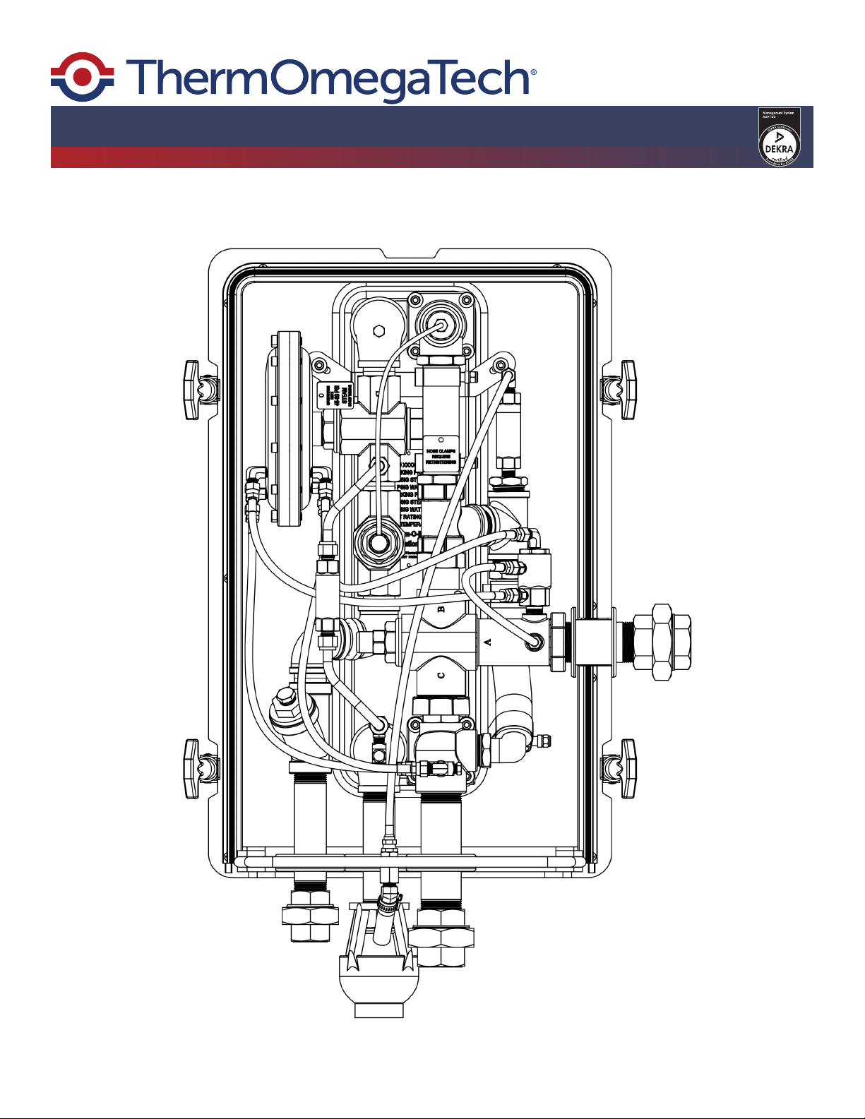
THERM-O-MIX®STATION
Troubleshooting Manual
| Technical Support: 1-800-766-5612 | Customer Service: 1-888-640-4297 |
D

Table of Contents
1.0 Introduction
1.1 Denitions and Terminology....................................................................................................2
1.2Checklist.................................................................................................................................2
2.0 Operating Sequence and Failure Modes
2.1 Normal Operating Sequence..................................................................................................3
2.2 Component Failure by Conditions..........................................................................................4
2.3 Troubleshooting Failure Modes..............................................................................................5
2.3.1 V1 Failure Mode..................................................................................................................5
2.3.2 V2 Failure Mode..................................................................................................................5
2.3.3 V3 Failure Mode..................................................................................................................5
2.3.4 V4 Failure Mode..................................................................................................................5
2.3.5 V5 Failure Mode..................................................................................................................5
2.3.6 V6 Failure Mode..................................................................................................................5
3.0 Decommissioning
3.1 Troubleshooting and Repair Warning Statement...................................................................6
3.2 Decommissioning the unit for Troubleshooting......................................................................6
3.3 Decommissioning the unit for Repairs...................................................................................6
3.4 Decommissioning Images......................................................................................................7
4.0 Adjustments and Repairs
4.1 V1 Mixing Valve......................................................................................................................8
4.2 V2 Capillary Valve..................................................................................................................9
4.3 V3 Diaphragm Valve..............................................................................................................9
4.4 V4 Control Valve....................................................................................................................10
4.5 V5 Control Valve..................................................................................................................11
4.6 V6 Valve...............................................................................................................................11
4.7 TV/HAT 155°F......................................................................................................................11
4.8 Heat Exchanger Cleaning....................................................................................................11
Section Page
Page
Page 1
Appendix #1: Station Schematic................................................................................................12
Appendix #2: Station Operating Logic Flow Chart.....................................................................13
Appendix #3: Typical Installation Schematic.............................................................................14
Appendix #4: Labeled Station Line Drawing..............................................................................15
Appendix #5: Hoses and Hose Fittings Line Drawing................................................................16
Appendix #6: Clean In-Place Instructions..................................................................................17
Appendices

Section 1.0: Introduction
This manual is designed to aid qualied personnel in troubleshooting and repairing of the
Therm-O-Mix® Station. Qualied personnel assigned to troubleshoot or repair a Therm-O-Mix®
Station should read the entire manual before proceeding. If you have any questions or concerns
about the information found in this manual, please contact ThermOmegaTech® at 1-877-379-8258.
Section 1.1: Denitions and Terminology
• System = safety shower/eyewash station
• Heater = Therm-O-Mix® Station tempered water unit
• Normal Range = tepid/moderately warm/lukewarm not to exceed 100F
• Flow Pressure = gauge pressure measured during ow (dynamic pressure)
• HtEx = stainless steel brazed plate heat exchanger
• V1 = primary mixing valve; mixes cold inlet water with heated water from V5
• V2 = normally open; controls hot water temperature out of HtEx by regulating steam ow into HtEx
• V3 = normally closed; pressure sensing diaphragm valve; opens in response to pressure
dierential across unit, allowing steam ow to HtEx
• V4 = normally closed; senses water temp out of mixing valve V1; V4 will open if the water
temperature is too high, short circuiting pressure dierential across diaphragm, closing V3 and
turning steam ow o
• V5 = normally open; pre-mixes cold water with hot water from heat exchanger prior to mix entering
the V1 mixing valve.
• V6 = normally closed; starts to open when water temp at valve approaches 95F due to heat soak
or heat migration.
Page 2
Section 1.2: Checklist
Review the below checklist before troubleshooting.
• Does the plant have adequate Steam Flow Pressure for the selected Therm-O-Mix® Station?
• Standard Pressure Steam Heater - Requires min. 45 PSIG/max. 60 PSIG. Above 60 PSIG
requires pressure regulator. Above 75 PSIG requires pressure regulator and relief valve.
• Lower Pressure Steam (LPS) Heater - Requires min. 15 PSIG/max. 30 PSIG. Above 30 PSIG
requires pressure regulator. Above 45 PSIG requires pressure regulator and relief valve.
• Is the station’s steam supply line properly sized? (Recommended min. 1” IPS)
• Does the plant have adequate Water Flow Pressure? (min. 55 PSIG while owing 25 GPM.)
• Is the station’s water supply line properly sized? (Recommended min. 1-1/4” IPS)
• Is the station’s supplying tepid water to anything other than the Safety Shower Station?
NOTE: Water ow from heater must be dedicated to safety shower/eyewash.
• Are freeze and scald protection valves installed correctly?
• Is the water supply line in contact with or being overheated by another source?
• Is the condensate properly sized? Is the condensate blocked?
Page 3
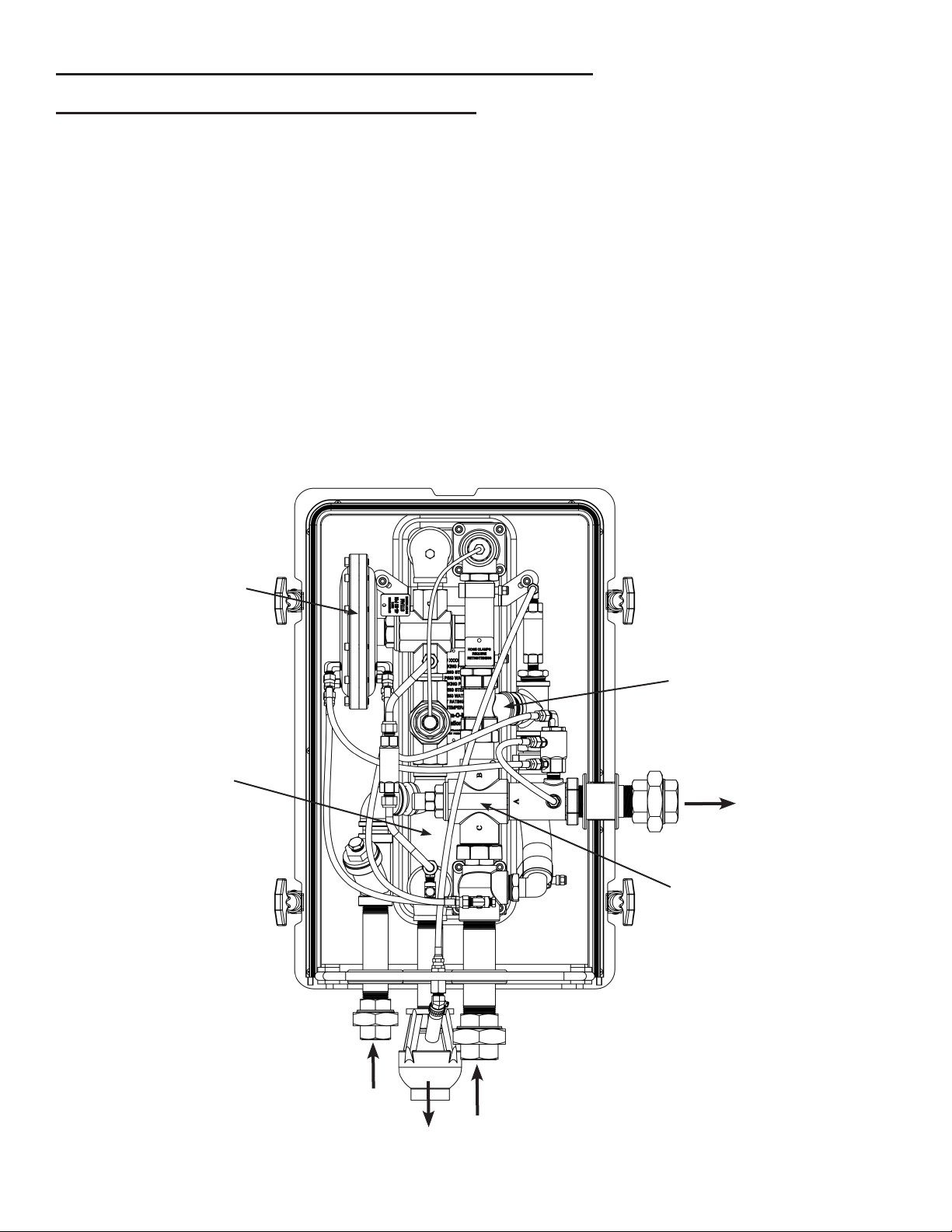
Section 2.0: Operating Sequence and Failure Modes
1. Activating the shower or eyewash station initiates cold water ow, resulting in a pressure drop in
the V3 Diaphragm and across the unit.
2. Cold water inlet tee directs ow to HtEx, V5 pre-mixing valve, and V1 mixing valve.
3. Steam heats cold water in the HtEx. V2 modulates steam ow based on water temperature from
HtEx.
4. Hot water from HtEx enters V5 pre-mixing valve, and mixes with cold inlet water.
5. The hot water enters V1 mixing valve and mixes with more cold inlet water, producing 80°F water
to supply the system.
(Refer to below diagram, Appendix #1 for Station Schematic, and Appendix #2 for Station Operation
Flow Chart.)
Section 2.1: Normal Operating Sequence
V3 Pressure Drop
Starts Steam Flow
Cold
Water
Steam
Condensate
Tepid
Water
Steam Heats Cold
Water In HtEx
V5 Pre-Mixing Valve
V1 Mixing Valve
Page 4
Section 2.2: Component Failure by Conditions
CONDITION COMPONENT FAILURE
If steam is coming out of the drain line while at
idle. ** Note: Some water vapor/condensate is
normal.
Conrm V3 is in closed position. Remove brass
pipe plug from reducing tee directly above the V3
diaphragm valve. Slowly open the steam supply
valve to see if steam ows past the V3 seat seal
into the reducing tee. If steam is present, V3 and
the valve body seal need to be repaired or re-
placed (Section 4.3). If steam is not present the
TV/HAT 155 needs to be replaced. (Section 4.7)
If the outlet temperature remains above the
normal range for long periods of time without
uctuation in the outlet temperature.
Follow Section 4.1 to check or replace V1 mixing
valve. Check V4 control valve and replace if not
functioning correctly.
If the outlet temperature uctuates, rising above
dropping below the normal range.
Follow Section 4.1 to check and/or adjust V1
mixing valve. If it cannot be adjusted, replace V1.
If the eyewash is running in the normal range,
but the shower runs below the normal range.
The V2 Capillary Valve needs to be adjusted.
(See Section 4.2)
If the eyewash runs above the normal range, but
the shower runs in the normal range.
**Note: Steam will probably be coming out of the
drain line while running the eyewash.
The V2 Capillary Valve needs to be adjusted
(See Section 4.2). If the valve cannot be ad-
justed correctly a replacement V2 Capillary is
required.
If there is a constant ow of warm water owing
through drain line.
V-6 has failed open. (See Section 4.6)
If there is an momentary temperature spike over
100 °F when ow begins.
V-6 has failed closed. (See Section 4.6)
Cold
Water
Only
If the V3 does not open allowing
steam to pass to the heat exchanger.
**Note: Check to see if the V3 indica-
tor does not move.
Inspect V3 to make sure it is not jammed (See
Section 4.3). Remove the V4 Control valve for
testing. (See section 4.4)
V3 opens approximately .300in., V1
is properly adjusted (See Section
4.1), V2 is open
Verify that steam is present at the Heater.
Remove the Y-strainer cap and check the screen
for debris. If the Heater is still not producing tepid
water the heat exchanger may be clogged with
minerals. The Heater can be ushed in place or
removed and ushed with the proper equipment.
If the proper equipment is not available the unit
can be returned to the factory for ushing and
recalibration.
V5 does not allow water to pass
through V1
Verify that the hot water line above V5 is hot
and hot side inlet to V1 is cold during operation.
Either the actuator has failed or cold water is
blocked.

Page 5
Section 2.3: Troubleshooting Failure Modes
If V1 failed with cold port closed (hot port open): hot water from outlet of HtEx ows to V5 premix
valve where hot inlet to V1 is combined with cold water to about 105F. This triggers V4 to close V3 so
no steam ows to HtEx and only cold water ows to shower/eyewash.
If V1 failed with hot port closed (cold port open): cold water into V1 ows to shower/eyewash.
Section 2.3.1: V1 Failure Mode
If V2 fails open: loss of steam ow control to HtEx. Full steam ow at all water temps. If V1 is
functional, it will proportion hot and cold-water ow to maintain 80°F output to system. If V4 is func-
tional, it will turn o V3 if output from V1 is too high. (Excess steam will escape through drain line.)
If V2 fails closed: no steam ow to HtEx; unit ows only cold water to system. Water outlet tee is
cold to the touch. Debris may be causing the steam valve to stay closed. At low ow the outlet tem-
perature will be about 80°F, at high ow the outlet temperature is below the required temperature.
Section 2.3.2: V2 Failure Mode
If V3 failed closed: no steam ow to HtEx; unit will output cold water; V3 indicator will not move.
If V3 fails open: steam ow to HtEx is always on. V2 controls temp of hot water out of HtEx. V1
mixes hot and cold water to control 80°F output; assume V4 cannot close V3, so V4 has no eect.
Steam will leak from the drain line even when the shower/eyewash unit is not activated. Large water
leaks (over 1 GPM) down stream would produce lower water pressure on the lower diaphragm
housing, possibly opening V3. Debris may be stuck in sealing area or V3 may be jammed open.
Section 2.3.3: V3 Failure Mode
If V4 failed closed: no signicance unless V1 also fails. Output temperature is over 95°F for more
than 15 sec.
If V4 failed open: steam will not turn on, so only cold water ows from the Heater. V3 may open
during the shower operation and allow steam to pass, but V3 will not open during eyewash operation.
Debris may be stuck to the seat area inside the V4 not allowing a good seal.
Section 2.3.4: V4 Failure Mode
Hot port closed: only cold water would be supplied to V1 and unit will output cold water.
Cold side port blocked: hot side will shut itself o, not supplying V1 at all and would produce
supply water temperature. Cold side port is not regulated so only a blockage can cause cold side port
to close water ow
Section 2.3.5: V5 Failure Mode
Valve failed closed: outlet water temperature “spike” to slightly over 100F for a couple of seconds.
Valve failed open: increased water discharge into drain connection.
Section 2.3.6: V6 Failure Mode
Note: Prior to starting any troubleshooting, look to see what is visible before activating water ow.
(Any leaks? Excess water or steam vapors from drain line? Any visible damage?)

Section 3.0: Decommissioning
Troubleshooting in the eld requires turning o the water and steam supply to the emergency safety
shower/eyewash system. Contact the plant safety manager/supervisor and follow proper procedures
for temporarily rendering the safety equipment unusable. Notify all personnel working in the area that
the emergency safety shower/eyewash equipment will be temporarily disabled.
Section 3.1: Troubleshooting and Repair Warning Statement
1. Close the unit’s steam supply valve.
2. Activate the shower and eyewash system for a minimum of two minutes to deplete the steam
pressure trapped between the steam supply shuto valve and the unit.
3. To remove the yellow enclosure, face the unit with outlet connection on your right. Un-clip the side
clamps and pull the bottom of the front cover towards you. The back cover is attached to the heat
exchanger by a stainless bracket and end bolts.
4. Once trouble shooting is complete, turn the steam supply on and activate the shower for at least
one minute to purge the system.
5. Insert the temperature-reading device into the eyewash nozzle. Activate the eyewash and record
the temperature several times over a 5-10 minute cycle. Note movement of V3 indicator and o-ring
on the V2 capillary valve. Repeat this step for the shower, attaching the temperature-reading
device to the shower-head. Record temperatures, V3 indicator, and capillary valve movement.
Section 3.2: Decommissioning The Unit for Troubleshooting
1. Close the unit’s steam supply valve.
2. Activate the shower and eyewash system for a minimum of two minutes to deplete the steam
pressure trapped between the steam supply shuto valve and the unit.
3. With the system activated, closer the water supply valve to the unit.
4. To remove the yellow enclosure, face the unit with outlet connection on your right. Un-clip the side
clamps. Pull the bottom of the front cover towards you. The back cover is attached to the heat
exchanger by a stainless bracket and end bolts.
5. Repair or replace components as needed.
6. Open the water supply valve to the Heater. Once water is owing open the steam valve slowly.
Allow he unit to run for at least one minute to purge the system.
7. Insert the temperature-reading device into the eyewash nozzle. Activate the eyewash and record
the temperature several times over a 5-10 minute cycle. Note movement of V3 indicator and o-ring
on the V2 capillary valve. Repeat this step for the shower, attaching the temperature-reading
device to the shower-head. Record temperatures, V3 indicator, and capillary valve movement.
8. Once the Heater is operating correctly close the steam supply line to the Heater.
9. Activate the shower and eyewash system for a minimum of two minutes to deplete the steam
pressure trapped between the steam supply shuto valve and the Heater.
10.Turn the steam supply back on and activate the shower for at least one minute.
11.Replace and secure the yellow enclosure.
Section 3.3: Decommissioning The Unit for Repairs
***WARNING: PIPING MAY BE HOT AND HOT WATER
MAY BE TRAPPED IN THE HEATER.
Page 6

Page 7
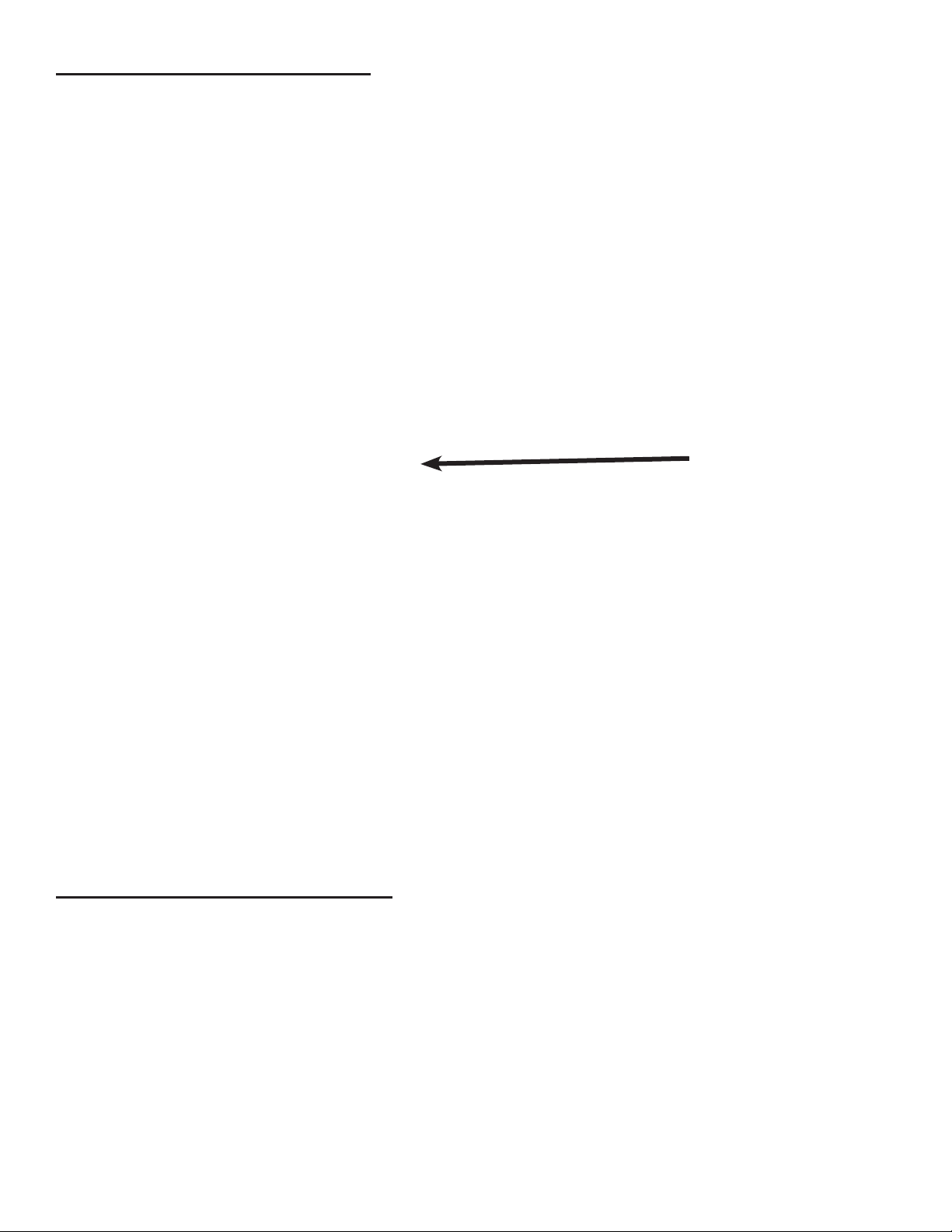
V3 Indicator
Open Position Closed Position
V2 Capillary Valve O-Ring
O-Ring
Indicator
Section 3.4: Decommissioning Images

Section 4.0: Adjustments and Repairs
V1 Mixing Valve Adjustment Outside of the Unit
1. Unscrew entire main valve cap from V1 mixing valve with a 1-1/2” wrench. The entire internal
assembly will pull out of the valve body in one piece.
2. Remove mixing valve cap nut with 1” wrench.
3. Loosen calibration lock nut with a 7/16” wrench.
4. Place valve into a 90°F water bath for ve minutes.
5. Use calibration screw to adjust the valve spool so that the inner spool cold water slots line up with
outer housing cold water slots so that cold side is fully open and hot side is fully closed. Place
valve into an 80°F water bath for ve minutes.
6. Use calibration screw to adjust the valve spool so that the inner spool hot water slots line up with
outer housing hot water slots so that hot side is fully open and cold side is fully closed.
7. Tighten the calibration jam nut.
8. Screw the mixing valve assembly back into the V1 mixing valve body.
Section 4.1: V1 Mixing Valve
Prior to beginning any repairs, follow all steps in section 3.3 to decommission the station. Test the unit
after all repairs have been completed to conrm full functionality.
V1 Mixing Valve Internal Assembly Replacement
Follow instructions provided with replacement part from ThermOmegaTech®
Remove Cap Screw
Remove Lock Nut
Adjust Calibration Screw
Page 8
Page 9
Section 4.3: V3 Diaphragm Valve
V3 Diaphragm Valve Test
1. To check the diaphragm for leaks plug one of the outside angle hose adapters and slowly apply
no more than 20-PSI air pressure to the other outside angle adapter. With the air pressure applied
to the adapter the seal holder should move o of the seat. When the pressure is released the seal
holder should move back. If air is continuously owing out of the inside angle hose adapters than
there is a hold in the diaphragm. If the Diaphragm Valve is not working correctly a replacement V3
is required.
V3 Diaphragm Valve Seal Replacement
Follow instructions provided with replacement part from ThermOmegaTech®
V3 Diaphragm Valve Replacement
Follow instructions provided with replacement part from ThermOmegaTech®
Section 4.2: V2 Capillary Valve
V2 Capillary Valve Adjustment
1. On the end of the heat dissipater nearest V2 valve body, there are four setscrews holding the
perforated heat dissipater to the valve. One of the four setscrews are substantially recessed and
only this one should be loosened. Newer units will only have the one locking setscrew located
closest to the V-2 valve.
2. After loosening the locking setscrew, turning the heat dissipater housing clockwise will lower the
hot water outlet temperature from the heat exchanger and also the water temperature from the
shower/eyewash. Turning the heat dissipater counterclockwise will raise the water temperature.
Rotate the heat dissipater a half turn at a time. Re-run the system after each adjustment.
3. Lock the setscrew on heat dissipater when nished.
V2 Capillary Valve Replacement
Follow instructions provided with replacement part from ThermOmegaTech®
Locking Screw

Section 4.4: V4 Control Valve
V4 Control Valve Test
1. Place V4 valve into a water bath at 98°F or above for ve minutes.
2. If you blow compressed air into the upper angled hose adapter the valve should be closed.
3. Place V4 into a water bath at 85°F or below for ve minutes.
4. If you blow compressed air into the lower straight hose adapter it should be closed.
5. If the valve does not work correctly a replacement V4 Control Valve is required.
V4 Control Valve Replacement
Follow instructions provided with replacement part from ThermOmegaTech®
Lower Hose Adapter,
From Outside V3
Middle Hose Adapter,
Dumps To Outlet
Upper Hose Adapter,
From Inside V3
Page 10

Page 11
Section 5.0: Heat Exchanger Cleaning
The Heater’s heat exchanger and capillary sensor may become clogged/coated with mineral deposits
over time and require cleaning with de-scaling solvents. Cleaning solution must be compatible with
copper alloys, EPDM, Stainless Steel, PTFE, and Buna-N O-rings. (Recommended manufacturer:
Armstrong’s Clean-In-Place Scale Removal System)
Unit can be cleaned while installed or disconnected at the unions and cleaned at another location.
Cleaning the unit while installed requires additional ttings (See Appendix #6). Tee ttings should be
installed on the water inlet supply line upstream from the inlet union and on the tepid water outlet line
downstream of the outlet union. Four locking ball valves will be needed to isolate the unit from the
plant water supply during cleaning. The rst ball valve should be installed upstream of the inlet tee,
the second installed on the leg of the inlet tee, the third installed downstream of the outlet tee, and
the last installed on the leg of the outlet tee where the cleaning system will be connected.
NOTE: Inlet and outlet layout may dier, depending on station version.
Pump solution into normal ow direction, check valves will prevent reverse ow. Cleaning
solution must remain below 80°F. The cleaning time needed depends on local water conditions and
frequency of cleaning. After the solution is drained, ush unit with potable water for 15 minutes to
prevent contamination. If the unit was cleaned while installed, complete the ush before opening the
isolation ball valves. Close the two ball valves on the legs of the tee and open the downstream ball
valve rst. Activate the shower/eyewash then open the upstream ball valve and allow the system to
run for several minutes. Open the steam supply valve and check the water outlet temperatures.
Section 4.5: V5 Tempering Valve
V5 Tempering Valve Test
1. If section 2.2 indicates V5 valve failure, decommission unit and replace V5 valve.
V5 Tempering Valve Replacement
Follow instructions provided with replacement part from ThermOmegaTech®
Section 4.6: V6 Valve
V6 Valve Test
1. If section 2.2 indicates V6 valve failure, decommission unit and replace V6 valve.
V6 Valve Replacement
Follow instructions provided with replacement part from ThermOmegaTech®
Section 4.7: TV/HAT 155°F
TV/HAT 155°F Valve Test
1. If section 2.2 indicates TV/HAT 155°F failure, decommission unit and replace TV/HAT155°F valve.
TV/HAT 155°F Valve Replacement
Follow instructions provided with replacement part from ThermOmegaTech®

Page 12
Appendix #1: Station Schematic

Appendix #2: Station Operating Logic Flow Chart
Page 13
Page 14
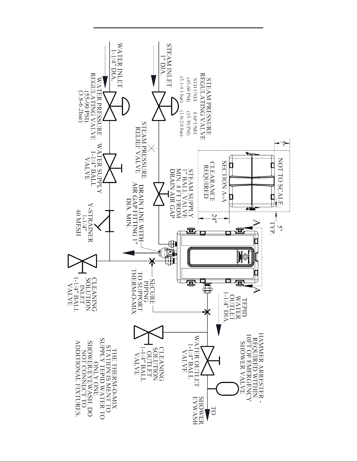
Appendix #3: Typical Installation Schematic

Appendix #4: Labeled Station Line Drawing
Page 15
Page 16
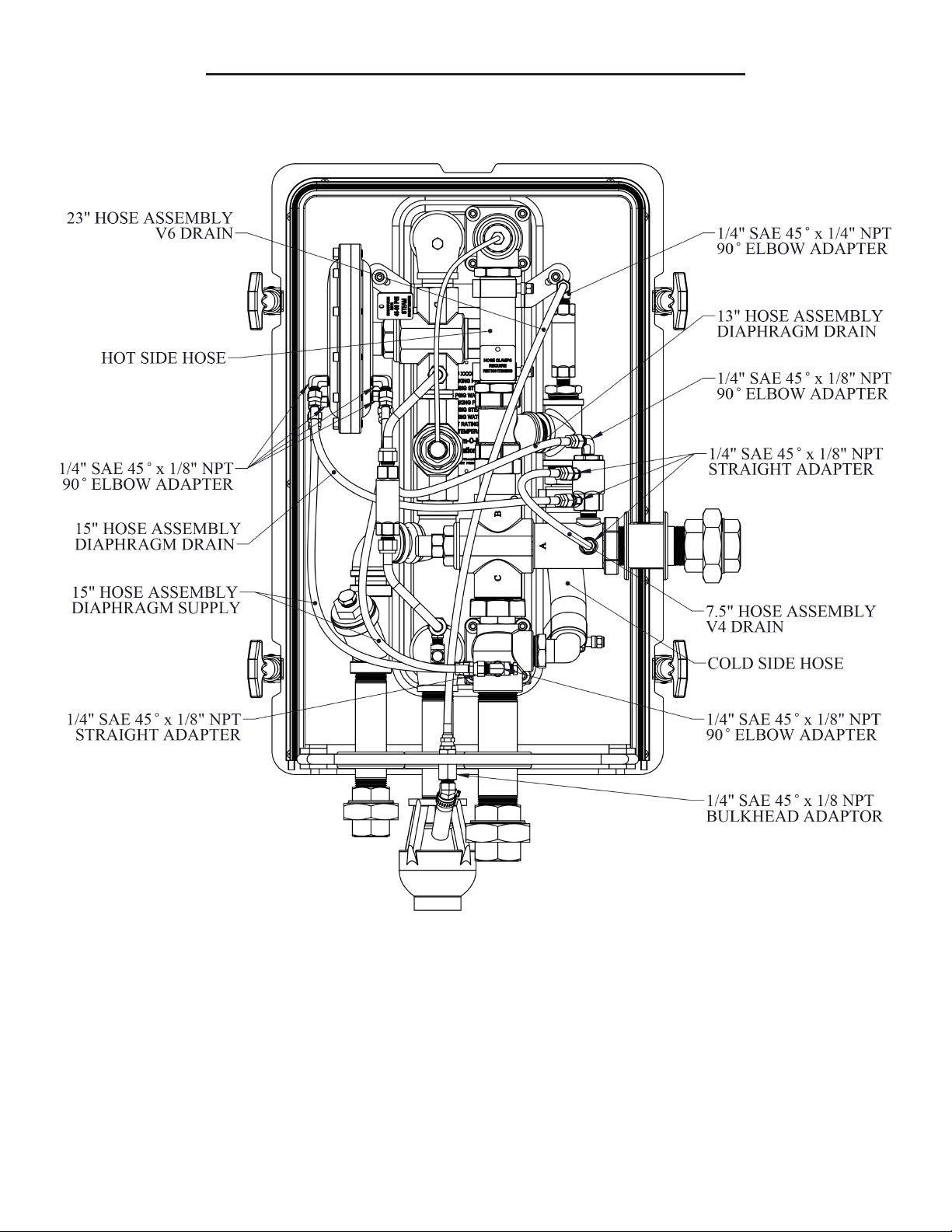
Appendix #5: Hoses and Hose Fittings Line Drawing

WARNING: This product can expose you to chemicals, for example lead, nickel, acrylonitrile, which are known to the State of
CA to cause cancer, birth defects, or reproductive harm. For more information, go to www.P65Warnings.ca.gov
ThermOmegaTech®, Inc.
353 Ivyland Road 1-877-379-8258
Warminster, PA 18974 www.ThermOmegaTech.com
MADE IN
THE USA
TOMix TS
Rev: 6/12/19
Appendix #6: Clean In-Place Instructions
Page 17
Table of contents


