ThermoPro TP-60S User manual

Wireless Indoor/outdoor Humidity And
Temperature Monitor Instruction Manual
Model No.: TP-60S
General Warning
This device contains electronic components which
operate via a power source (power supply and/or
batteries). Do not let children use the device while
unattended. Only use the device as described in the
manual, otherwise you run the risk of an electric shock.
Children should only use the device under adult super-
vision. Keep packaging material, like plastic bags and
rubber bands, out of the reach of children,as they pose
a choking hazard.
DANGER!
Introduction
Congratulations on your purchase of the wireless indoor/
outdoor humidity and temperature monitor. You will now
be able to know the outdoor/indoor temperature and
humidity while sitting inside.
-28- -29-
EN EN

-30- -31-
EN
Do not disassemble the device. In the event of a defect,
please contact your dealer. The dealer will contact the
Service Centre and can send the device in to be repaired,
if necessary.
NOTE!
Use only the recommended batteries. Always replace
weak or empty batteries with a new, complete set of
batteries at full capacity. Do not use batteries from di-
fferent brands or with different capacities. The batteries
should be removed from the unit if it has not been used
for a long time.
Notes on cleaning
Separate the device from the power supply or remove
the batteries before cleaning.
DANGER!
Do not expose the device to high temperatures.Use
only the recommended batteries. Do not shortcircuit the
device or batteries, or throw them into a fire. Excessive
heat or improper handling could trigger a shortcircuit, a
fire or an explosion!
EN
Only use a dry cloth to clean the exterior of the device.
Do not use any cleaning fluid to avoid damaging the
electronics.
Keep batteries out of the reach of children. Make sure
you insert the batteries correctly. Empty or damaged
batteries could cause burns if they come into contact
with the skin. If necessary, wear adequate gloves for
protection.
Hints and Tips
If the receiver does not connect to the transmitter, try
the following:

Press and hold the CHANNEL/SYNC button on the
base station and then press TX button on the
transmitter.
Relocate the base station and/or the remote unit until
connection is found.
Signals from other electronic devices may cause
interference. Place the base station and receiver
away from these devices.
The transmitter may not function properly in extreme
temperatures due to battery power. Replace the
batteries or the unit will resume proper function in
more moderate weather.
If the base station is attached to a refrigerator or a
metal object by magnet, the transmission may be
shorter. Remove the base station from the refrigera-
tor or the metal object or place the base station and
remote sensor as close as possible.
If the Humidity is lower than 10%, it will display LLL.
Warnings
Do not subject the unit to excessive force, shock,
dust, temperature or humidity.
Do not immerse the unit in water.
Do not remove any screws.
Do not dispose this unit in a fire. IT MAY EXPLODE.
Keep unit away from small children. The unit or parts
of the unit might be a choking hazard.
Never attempt to recharge the batteries using any
other methods.
Dispose of the unit legally and recycle when possible.
Components
1. One base station unit (Receiver).
2. One remote sensor (Transmitter).
-32- -33-
EN EN
Although the remote sensor is designed to be rain-
proof, the remote sensor must be always placed
upwards so that rain won't get inside the sensor
through the vent holes on the bottom of the senor
which functions to let the remote sensor detect the
environmental temperature and humidity more
precisely and quickly.
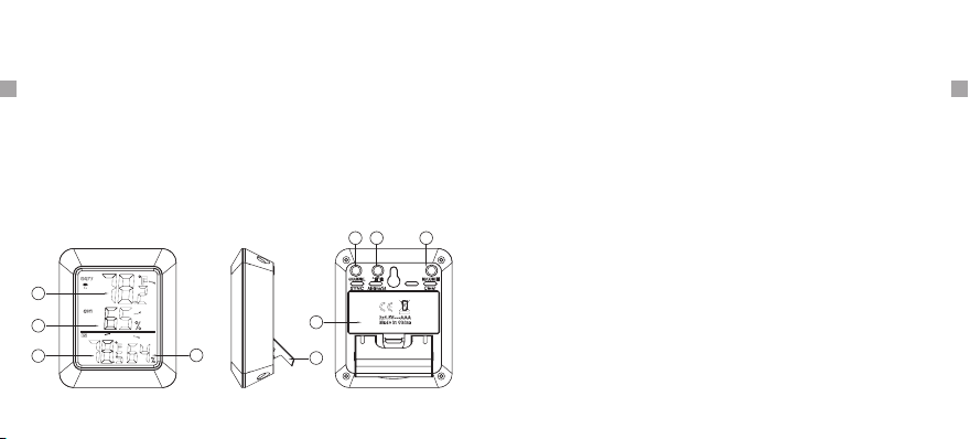
Indoor Base Station (Receiver) Features
1.
2.
3.
4.
5.
Outdoor temperature
Outdoor humidity
Indoor temperature
Indoor humidity
Stand
6. Channel/SYNC
7. °C/°F/All time/24
8. MAX/MIN/Clear
9. Battery Compartment
1
2
345
78
6
9
1. LCD display: Displays the current outdoor humidity/
temperature and indoor humidity/temperature.
2. Battery Compartment: Holds 2 AAA batteries to
power the unit.
3. Tabletop and wall-mounted design.
4. Indoor Temperature range: -4°F~158°F(-20°C~70°C).
5. Humidity range: 10% ~ 99%.
6. Temperature display unit: °C and °F selectable.
7. Temperature Resolution: 0.1 °C/°F.
8. Humidity Resolution:1%.
9. Low battery indication.
-34- -35-
EN EN

-36- -37-
EN EN
Buttons
CHANNEL/SYNC: Press once to display the tempera-
ture and humidity readings from up to 3 outdoor remote
sensors; Press and hold this button to enter the
synchronization mode.
MAX/MIN/CLEAR: Press once to display the maximum
or minimum temperature and humidity; Press and hold
to clear the history data.
°
mum or minimum temperature and humidity, press this
button once to set the maximum and minimum data
record time interval between ALL TIME or 24 hours.
Note: Both ALL TIME and 24 hours represent the time
since you last time manually cleared the history data
or installed a new battery.
F/°C/ALL-TIME/24: Press to select the temperature
display in ºC or ºF; When the display shows the maxi-
1. indicates the temperature & humidity is in an
increasing trend.
Temperature & Humidity Trend
2. indicates the temperature & humidity is in an no
change trend.
3. indicates the temperature & humidity is in a
decreasing trend.
Outdoor Remote Sensor (Transmitter) Features
3
1
2
4
5
76
-38- -39-
EN EN
Buttons
CHANNEL Selector (1,2,3): Slide to set Channel 1,2
or 3.
RESET: Press once to reset the remote sensor.
1. Battery Compartment: Holds 2 X AAA batteries to
power the unit.
2. Rain-proof and design.wall-mounted
3. Outdoor Temperature range: -58° ~158°F (-50°C
~70°C).
4. Humidity range: 10% ~ 99%.
TX: Press to send temperature/humidity data to the
receiver manually.
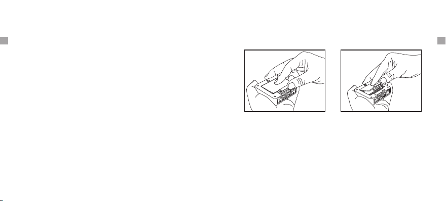
Battery Installation and Setup
1. Open the battery compartment of the remote sensor
as below Figure;
2. Slide the channel selector switch inside the battery
compartment to your desired channel. For the first
remote you may select any channel, for additional
remotes select any unused channel;
3. Insert (2) AAA batteries according to the polarity
markings. Replace the battery compartment cover;
4. Open the battery compartment at the back of the base
1. TX LED
2. Wall hanging hole
RESET
4. TX
3.
5. Channel 1.2.3
6. 2*AAA battery
Sensor detection port7.

station and insert (2) AAA batteries according to the
polarity markings. Replace the compartment door;
5. Press the °F /°C button at the back of the base station
to display the temperature in °F or °C.
For maximum performance in normal conditions we
recommend using good quality alkaline batteries.
If the battery power is low, there will be low battery icon
showing on the base station display.
Synchronize Remote Sensors with The Base
Station
1. Position the remote sensor near the base station;
2. Once the batteries are installed in the base station,
the RF signal icon . (located on the upper left of the
base station display) will flash for 3 minutes, indica-
ting that the base station is in synchronization mode:
it is waiting for remote sensors to be registered.
3. If 3 minutes have passed after the batteries were
installed in the base station and the RF signal Icon is
no longer flashing, press and hold the CHANNEL/
SYNC button on the back of the base station for 3-4
seconds until the RF signal icon is flashing again to
set it back in synchronization mode;
Do not mix old and new batteries.
Do not mix alkaline, standard (carbon zinc), or rechar-
geable (nickel cadmium) batteries.
Note:
Please note: each time the batteries (inserted into either
base station or remote sensor) are replaced or base
station/remote sensor lost
follow the below synchronization process to pair and
re-connect the base station and remote sensor:
connection, make sure to
4. Install the batteries in the remote sensor and wait for
a moment or just press either the TX or RESET button
-40- -41-
EN EN

-42- -43-
EN EN
inside the remote sensor battery compartment, the
remote sensor temperature/humidity will show on
the base station display which indicates the
synchronization is complete.
5. If you have additional remote sensors, repeat the
above steps to register the remote sensors (up to
3 remote sensors can be registered with one base
station);
6. If you have registered more than one sensor, press
the CHANNEL/SYNC button on the base station to
select the remote channel you want displayed per-
manently on the base station. Press CHANNEL/
SYNC button until you observe a circular arrow on
the base station LCD display under the channel
number. The unit will then auto-scroll, changing
from channel to channel every 5 seconds.
NOTE: If you have additional remote sensors, when you
are
the unit will keep changing from channel to channel in
the first three minutes, after that you can select any
channel you like or auto-scroll mode.
synchronizing remote sensors with the base station,
2. The remote sensor (transmitter) can be placed on a
flat surface indoor or outdoor. Make sure the sensor
is within the transmission distance from the base
station and with minimal obstructions.
3. The base station and remote sensor can both be
wall mounted.
NOTE: Although the remote sensor is designed to be
Place the Base Station and Remote Sensor
1. The indoor base station (receiver) should always be
placed in a well ventilated indoor area and located
away from vents, heating or cooling elements, direct
sunlight, windows, doors, or any other openings.

-44- -45-
EN EN
Maximum & Minimum Recorded Temperature
& Humidity
1. Press MAX/MIN/Clear button once to display the hi-
ghest indoor and outdoor temperatures/humidity re-
corded since last reset. MAX is shown on the display.
2. Press MAX/MIN/Clear button again to display the
lowest indoor and outdoor temperatures/humidity re-
corded since last reset. MIN is shown on the display.
3. To clear and reset the max/min records, when either
the MAX or MIN record is shown on the LCD display,
press and hold MAX/MIN/Clear for 3 seconds.
4. When either the MAX or MIN record is shown on the
LCD display, press ALL-TIME/24 button once to set
the data record time interval between ALL TIME or 24
hours. Note: Both ALL TIME and 24 hours represent
the time since you last time manually cleared the
history data or battery installation.
Purchasing Additional Remote Sensors
The model number of the remote sensor for this unit
is TPR65.
Additional sensors may be ordered directly from Amazon
or ThermoPro by contacting our customer service listed
below.
rain-proof, the remote sensor must be always placed
upwards so that rain won't get inside the sensor through
the vent holes on the bottom of the senor which functions
to let the remote sensor detect the environmental tem-
perature and humidity more precisely and quickly.
Specifications
1. 433 Mhz transmission frequency.
2. Transmission range up to 200 ft. (range maybe

-46- -47-
EN EN
shorter based on interference present).
3. Indoor Temperature range: -4°F~158°F (-20°C~70°C).
4. Outdoor Temperature range: -58°F~158°F (-50°C~
70°C).
5. Humidity range: 10% ~ 99%.
6. Temperature tolerance: +/- 2.0°F (+/- 1.1°C).
7. Humidity tolerance: ±2% from 30% to 80%; ±3%
below 30% and above 80%.
8. Power: 2 X AAA 1.5V for base unit and 2 X AAA 1.5V
for remote sensor.
FCC Statement of Compliance
This device complies with Part 15 of the FCC rules.
Operation is subject to the following two conditions:
l) This device may not cause harmful interference.
2) This device must accept any interference received,
including interference that may cause undesired
operation.
Warning: Changes or modifications to this unit not ex-
pressly approved by the party responsible for compliance
could void the user's authority to operate the equipment.
NOTE: This equipment has been tested and found to
comply with the limits for a Class B digital device, pur-
suant to Part 15 of the FCC rules. These limits are de-
signed to provide reasonable protection against harmful
interference in a residential installation. This equipment
generates, uses and can radiate radio frequency energy
and, if not installed and used in accordance with the
instructions, may cause harmful interference to radio
communications. However, there is no guarantee that
interference will not occur in a particular installation. If
this equipment does cause harmful interference to radio
or television reception, which can be determined by
Other manuals for TP-60S
2
Table of contents
Other ThermoPro Monitor manuals


