ThermoTex SorTexx User manual
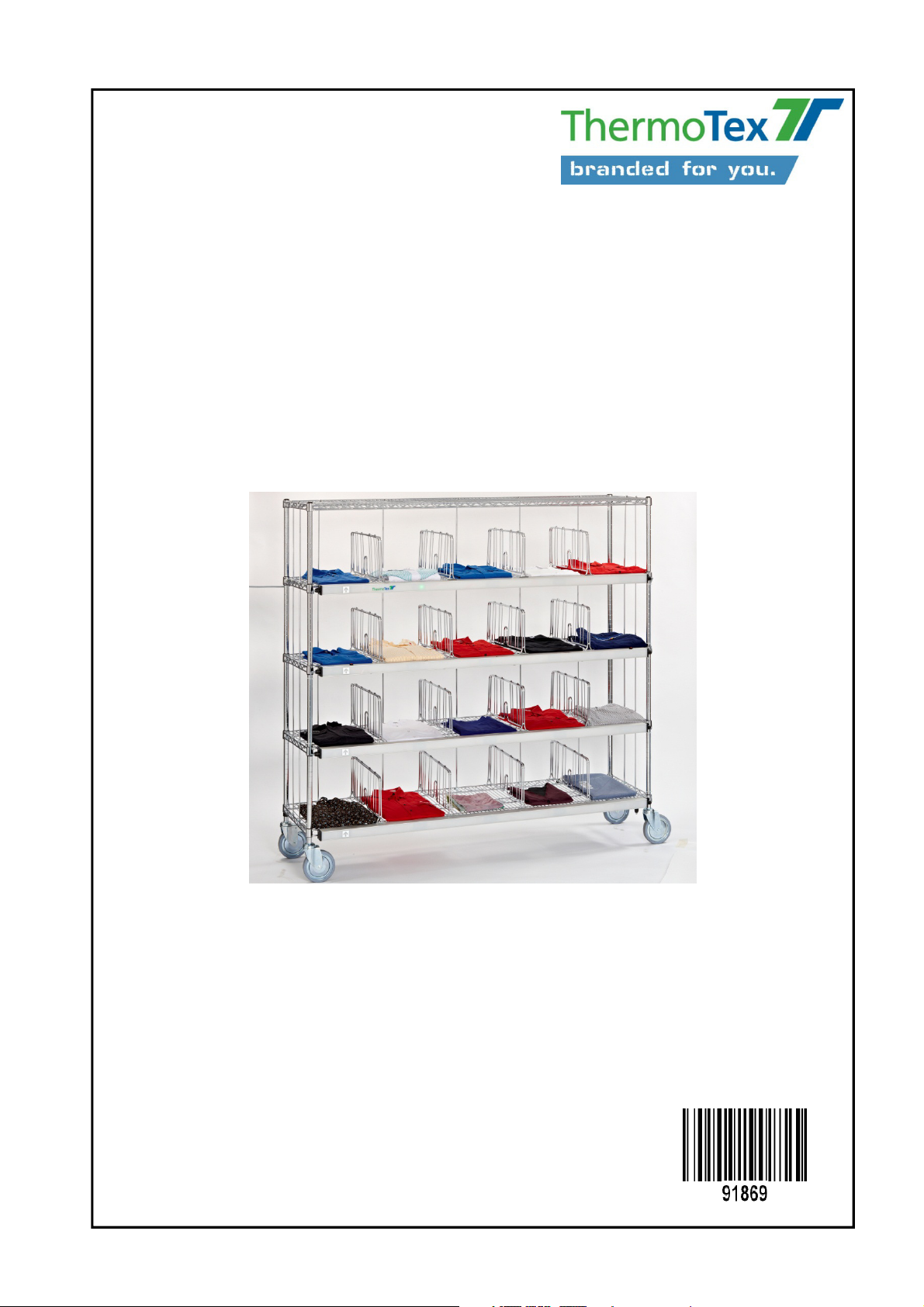
ThermoTex Nagel GmbH
Schutterstr. 14, 77746 Schutterwald, GERMANY
Phone +49 781 9616-0, fax +49 781 9616-50
Operating Manual for
SorTexx
- Translated Version of the Original Operating Manual -

Contents
1 Product description..................................................................................................................4
1.1 General description, proper use ....................................................................................................................4
1.1.1 Laundry receipt: receipt sorting system IN-SorTexx ......................................................................4
1.1.2 Laundry receipt: Light sensor frame...............................................................................................5
1.1.3 Laundry expediting: expediting sorting system OUT-SorTexx.......................................................6
1.2 Structure ........................................................................................................................................................7
1.3 Scope of supply .............................................................................................................................................7
1.4 Technical data ...............................................................................................................................................7
1.5 Declaration of conformity...............................................................................................................................8
2 Safety instructions....................................................................................................................9
2.1 Warning symbols ...........................................................................................................................................9
2.2 Hazard zones on the device..........................................................................................................................9
2.3 Safety devices ...............................................................................................................................................9
2.4 Operator's duty to take care ..........................................................................................................................9
2.5 General safety measures during normal operation .......................................................................................9
2.6 General safety measures during maintenance and servicing .....................................................................10
3 General information................................................................................................................10
3.1 Instructions for positioning the machine......................................................................................................10
3.2 Initial commissioning ...................................................................................................................................11
3.2.1 Connecting the sorting systems to the LED control unit: .............................................................11
3.2.2 Connecting the sorting systems to the repeater:..........................................................................12
3.2.3 Connecting the PC to the LED control unit: .................................................................................12
3.2.4 Connecting the signal transducer to the LED control unit............................................................12
3.2.5 Connecting the LED control unit to the power supply ..................................................................12
3.3 Examples.....................................................................................................................................................13
3.3.1 IN-SorTexx, one row of modules type “mounting set left”............................................................13
3.3.2 IN-SorTexx, one row of modules type “mounting set right”..........................................................13
3.3.3 IN-SorTexx, two module rows ......................................................................................................13
3.3.4 OUT-SorTexx, one row of modules type “frame left” ...................................................................13
3.3.5 OUT-SorTexx, one row of modules type “frame right” .................................................................13
3.3.6 OUT-SorTexx, two module rows ..................................................................................................14
3.3.7 OUT-SorTexx, incomplete shelf at end of row .............................................................................14
3.4 Acknowledgement .......................................................................................................................................14
3.4.1 Waiting for acknowledgement (automatic) ...................................................................................14
3.4.2 Waiting for acknowledgement (PC software) ...............................................................................14
4 Operation.................................................................................................................................15
4.1 Switching on ................................................................................................................................................15
4.2 Menus..........................................................................................................................................................16
4.2.1 Choose Language ........................................................................................................................16
4.2.2 Daily counter, total counter and operating hours .........................................................................16
4.2.3 LED test........................................................................................................................................17
4.2.4 Button test ....................................................................................................................................17
4.2.5 Beacon test...................................................................................................................................17
4.2.6 Rack type......................................................................................................................................17
4.2.7 Merge racks..................................................................................................................................17
4.2.8 Wait for confirmation ....................................................................................................................17
4.2.9 Use buffer memory.......................................................................................................................17
4.2.10 Alarm signal for wrong compartment ...........................................................................................18
4.2.11 Alarm if shelf not confirmed..........................................................................................................18
4.2.12 Automatic OFF .............................................................................................................................18
4.2.13 Settings for operation mode ”Counting frame“ .............................................................................18
4.2.14 Network settings...........................................................................................................................18
4.3 F1 and F2 ....................................................................................................................................................18
5 Data protocol...........................................................................................................................19
5.1 Basic principles of communication ..............................................................................................................19
5.2 Command ....................................................................................................................................................19
GBSOTXBA_V(1).DOC

Contents
GBSOTXBA_V(1).DOCX Page - 3
5.3 Answer.........................................................................................................................................................19
5.4 Start codes and end codes..........................................................................................................................20
5.5 Description of the commands......................................................................................................................20
5.5.1 LEDs exclusive ON ......................................................................................................................20
5.5.2 LED cumulative ON......................................................................................................................20
5.5.3 LED cumulative OFF ....................................................................................................................20
5.5.4 Read button ..................................................................................................................................21
5.5.5 Clear button ..................................................................................................................................21
5.5.6 Poll number of modules................................................................................................................21
5.5.7 Poll version number......................................................................................................................21
5.5.8 Enforce acknowledgement ...........................................................................................................21
5.5.9 Reset ............................................................................................................................................22
5.5.10 Signal transducer ON and OFF....................................................................................................22
5.5.11 Sensor delay time.........................................................................................................................22
5.5.12 Counting frame: Poll counter value ..............................................................................................22
5.5.13 Counting frame: Clear counter value ...........................................................................................23
5.5.14 Poll operation mode .....................................................................................................................23
5.6 Examples.....................................................................................................................................................23
5.6.1 One LED ON (without acknowledgement) ...................................................................................23
5.6.2 One LED ON (with acknowledgement) ........................................................................................23
5.6.3 All LEDs of all modules OFF ........................................................................................................23
5.6.4 Signal transducer ON ...................................................................................................................23
5.6.5 Reset ............................................................................................................................................23
5.6.6 Button poll (individual module) .....................................................................................................24
5.6.7 Button poll (all modules)...............................................................................................................24
6 Servicing and maintenance....................................................................................................24
7 Troubleshooting .....................................................................................................................25
8 Accessories and spare parts .................................................................................................25
9 Circuit diagram .......................................................................................................................26

Product description
GBSOTXBA_V(1).DOCX Page - 4
1 Product description
The SorTexx laundry sorting system sorts laundry reliably in goods receipt and expediting.
The LED control unit SC02 controls the corresponding LED for the compartment (or container) into which the
laundry is to be sorted, as stipulated in the corresponding laundry management software.
Three different colours (green, red, yellow) can be activated for each compartment.
In operation mode „Counting Frame“ the device counts the laundry pieces that are dropped into different
containers. Up to 10 light sensor frames can be connected. The maximum counter value for each frame is 9999.
1.1 General description, proper use
The SorTexx laundry sorting system is available in two versions:
•IN-SorTexx for laundry receipt (IN-coming)
•OUT-SorTexx for laundry expediting (OUT-going)
The bus system permits simple addition of several sorting shelf trolleys with the same number of compartments.
The corresponding connectors are already fitted. When there are more than 80 compartments, the system has
to be fitted with a repeater for signal processing.
The LED control unit SC02 is the central component and is needed to activate the LEDs in both laundry receipt
and laundry expediting.
Communication with the laundry management program takes place using the transmission protocol (see chapter
5 for the command structure).
Please note that the laundry management software switches on max. 10 LEDs at the same time. Switching on
more than this number is not checked by the LED control unit.
The LED control unit is equipped with a graphic display and a touchpanel for adjusting or changing the menu
settings.
The menu structure and displays differ for laundry receipt and laundry expediting. (See chapter 4 for the menu
description)
Safe operation of the machine is not warranted if the laundry sorting system is not used
for its intended purpose.
Compliance with all information in the operating manual is an integral part of proper use.
1.1.1 Laundry receipt: receipt sorting system IN-SorTexx
•Mounting system type “right” (MR) or “left” (ML) for mounting directly to the wall (see Fig. 1)
•Frame type “right” (GR) or “left” (GL): collection containers are under the frame (see Fig. 2)
•No. of LEDs: depending on the number of collection containers being used (standard: 3 to 5 per unit)
•Left/right version (position of mounted connection lead):
connected to the left: counting always from left to right
connected to the right: counting always from right to left

Product description
GBSOTXBA_V(1).DOCX Page - 5
Type designation syntax (IN-SorTexx):
ISxxxxSyy-at IS: Laundry receipt sorting system (IN-SorTexx)
xxxx: Width in mm
S: Total number of collection points
yy: Number of collection points:
a: Structure (G= frame, M= mounting system)
t: Type (R= right, L= left)
Fig. 1 (IS2000S05-ML) Fig. 2 (IS2000S03-GL)
1.1.2 Laundry receipt: Light sensor frame
•Size: 280 x 280 mm or 500 x 650 mm
•Single frame „right“ or „left“ for custom installation
•Frame type „right“ (GR) or „left“ (GL): collection containers are under the frame
•Left/right version (position of mounted connection lead):
connected to the left: counting always from left to right
connected to the right: counting always from right to left
Type designation syntax (light sensor frame):
LSRxxxxEy-at LSR: Light sensor frame
xxxx: Width in mm
yy: Number of collection points
a: Structure (G = frame)
t: Type (R = right, L = left)
Fig. 3 (LSR1250E3-GL) Fig. 4 (LSR1920E3-GL)

Product description
GBSOTXBA_V(1).DOCX Page - 6
1.1.3 Laundry expediting: expediting sorting system OUT-SorTexx
•Mounting system type “right” (MR) or “left” (ML) for mounting directly to the sorting shelf trolley
(see Fig. 5)
•“Frame” version (GR/GL): sorting shelf trolley runs directly behind the frame (see Fig. 6)
•Number of compartments per sorting shelf trolley: 20, 24, 25 and 30 compartments
•Left/right version (position of mounted connection lead):
connected to the left: counting always from left to right
connected to the right: counting always from right to left
•Optional: acknowledgement button (see Fig. 7) or acknowledgement light barrier (see Fig. 8).
Type designation syntax (OUT-SorTexx):
zz OSxxxxFyy-at
zz: Acknowledgement option
LS: light barrier
TA: button
OS: Expediting sorting system (OUT-SorTexx)
xxxx: Width in mm
F: Total number of compartments
yy: Number of compartments:
a: Structure (G= frame, M= mounting system)
t: Type (R= right, L= left)
Fig. 5 (OS1830F20-ML) Fig. 6 (OS1830F20-GL)
Fig. 7 (Button acknowledgement) Fig. 8 (Light barrier acknowledgement)

Product description
GBSOTXBA_V(1).DOCX Page - 7
1.2 Structure
The SorTexx laundry sorting system consists of the LED control unit with display which is connected to the
sorting frame (or mounting system) by means of a connection lead.
Several frames/mounting systems can be “connected up in succession”. To this end, the connector is connected
with the coupling plug.
OUT-SorTexx: Only sorting shelf frames/mounting systems with the same number of
compartments may be connected together.
The LED control unit is connected to the PC where the laundry management software is installed, by means of
a serial interface, USB or Ethernet network connection.
A signal transducer can be used as an option for visual and/or acoustic error signalling.
Only the power cable included in the scope of supply may be used to connect the system to the 230V power
supply.
The cable is plugged into the rubber connector of the power entry module of the LED control unit, which also
has a power switch and a double fuse holder.
1.3 Scope of supply
•1 x SorTexx LED control unit SC02
•Power supply cable
•1 x SorTexx connection length (customised length)
•SorTexx sorting shelf system (customised type and quantity)
You also need suitable PC software to activate the SorTexx system.
1.4 Technical data
Type designation: SorTexx laundry sorting system
Electrical ratings: 230 V, 50 Hz
Rated current: < 1 A
Fuse: 1.6 A (M)
Control unit dimensions: 300 x 300 x 150 mm (w x h x d)
Control unit weight: 7 kg

Product description
GBSOTXBA_V(1).DOCX Page - 8
1.5 Declaration of conformity
CE Declaration of Conformity
Manufacturer:
ThermoTex Nagel GmbH
Schutterstraße 14
D-77746 Schutterwald
Device description:
Type: SorTexx laundry sorting system
Production status: January 2014
The device fulfils the health and safety requirements of the following EC directives:
•Low voltage directive 2006/95/EC
Applied standard: EN 60204-1:2006
•Electromagnetic compatibility directive 2004/108/EC
Applied standards: EN 61000-6-2:2005
EN 61000-6-3:2007
Schutterwald, 14 January 2014
ThermoTex Nagel GmbH
Dietmar Nagel
(Managing Director)
Safety instructions
GBSOTXBA_V(1).DOCX Page - 9
2 Safety instructions
2.1 Warning symbols
The following warning symbols are used on the device and in this manual:
“Hazard warning”
“Warning, dangerous electrical voltage”
“Warning, noise with high sound pressure
level”
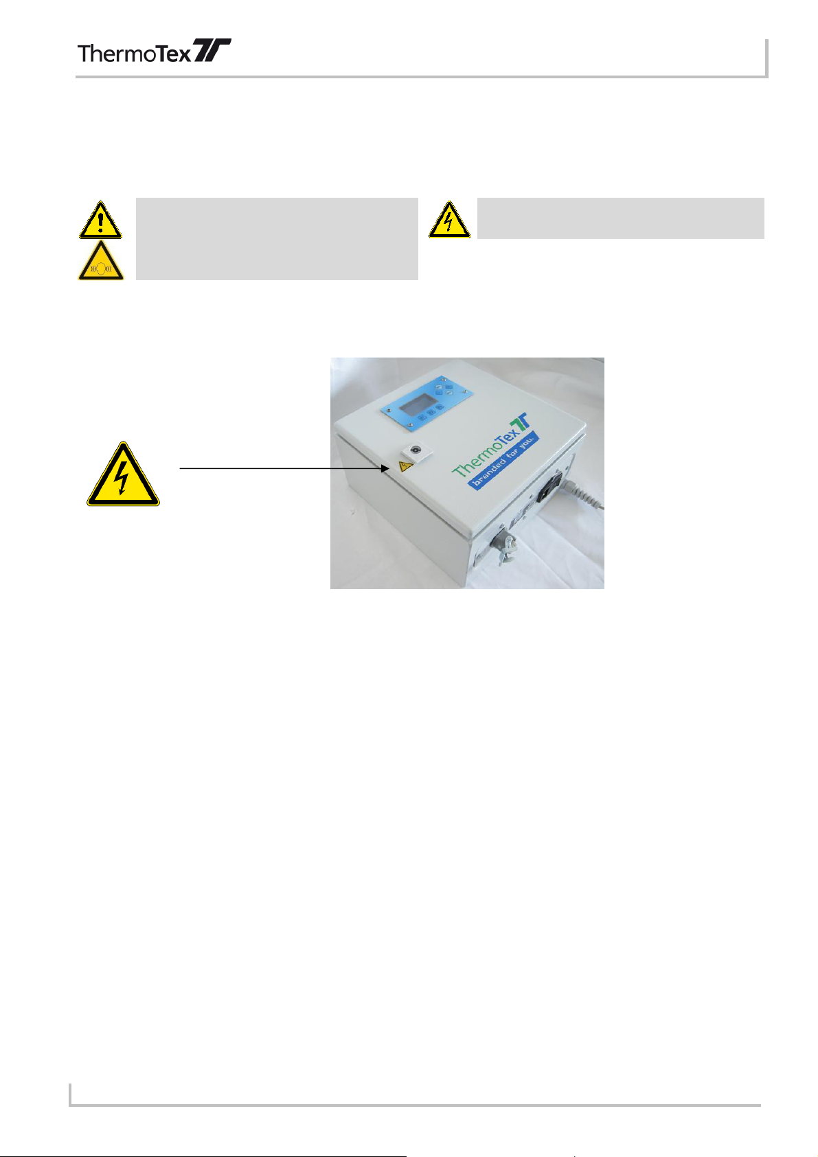
2.2 Hazard zones on the device
Fig. 1 LED control unit / repeater
LED control unit / repeater: disconnect from the power supply before opening the housing!
2.3 Safety devices
•The LED control unit is protected with two microfuses 2.5 A (slow).
2.4 Operator's duty to take care
The operator must ensure in particular that
•the device is only used for its intended purpose (see chapter 1)
•no unauthorised modifications and changes are made to the machine
•the device is only operated in flawless, functional condition
•the manual is always kept in legible, complete condition at the site where the device is being used
•only qualified and authorised staff operate, maintain and repair the device
•these members of staff are regularly instructed in all relevant issues of occupational health and safety as
well as environment protection, and are familiar with the manual and in particular its safety instructions
•all safety and warning signs affixed to the device are not removed and are in legible condition
2.5 General safety measures during normal operation
Make sure that none of the device leads are damaged.
The installation instructions must be heeded as stated in this manual, particularly for the versions installed on
site. (See chapter 3.2)

Safety instructions
GBSOTXBA_V(1).DOCX Page - 10
2.6 General safety measures during maintenance and servicing
•Repair work to electrical equipment of the device must only be carried out by a
trained electrician!
•Switch the device off and disconnect it from the power supply before carrying out
any maintenance and repair work!
Caution: This also applies to the repeater, if used.
3 General information
3.1 Instructions for positioning the machine
Before commissioning the device, please give some thought as to where the sorting shelf system should be
positioned.
•The sorting shelf system should be positioned on a firm, flat surface.
•Frames for laundry receipt/expediting must be screwed firmly to the floor using the holes provided in the two
side parts (fastening material not included in the scope of supply)
Fig. 2 Fastening the frame
•Screw the mounting system for the laundry receipt area firmly to the wall using the provided fastening
brackets (further fastening material not included in the scope of supply)
•Control unit:
Screw to the wall or take suitable precautions (e.g. mounted flat on the desk top) to make sure that there is
no risk of it falling down.
•The device may only be used in dry, indoor areas.
•The machine must not be positioned in an explosive environment.

General information
GBSOTXBA_V(1).DOCX Page - 11
3.2 Initial commissioning
•Customer's power socket with max. fuse of 16 A.
•Only the supplied power cable may be used to connect the device.
•The power socket must be in easy reach.
•Connect up the frame or mounting system before the LED control unit is switched
on.
Fig. 3: Connections of the LED control unit
3.2.1 Connecting the sorting systems to the LED control unit:
Connecting the frame/mounting system to the LED control unit for both laundry receipt and laundry expediting is
as described below.
Please note that the mounting position of the connector is either on the left (“left” type; counting always from
left to right) or on the right (“right” type, counting always from right to left). It is possible to connect up 2 rows of
modules. Module counting begins at connector plug 1.
a) Connecting one row of modules:
After securely mounting the LED control unit, connect the plug (pin) of the supplied connection lead to the
connector plug 1 of the LED control unit and close the retaining clip. Insert the coupling plug of the connection
lead into the connector of the first frame/mounting system and close the retaining clip.
Further frames/mounting systems are then connected up in the same way as connecting up to the LED control
unit, with the difference that the connector of the next system is inserted into the coupling plug of the last
connected system (left or right type) and locked in position.
To this end, both the frames and the mounting systems are provided with a connector and a coupling plug.
b) Connecting the frames or mounting system arranged in two lines:
If the frames/mounting systems are to be arranged in two lines (e.g. to the left and right of the control), please
proceed with connection according to the examples shown in chapter 3.3.
•A repeater is needed to connect up more than 80 modules (or 50 modules with
light barriers)
•Out-SorTexx: Only systems of the same type (with the same number of
compartments) can be combined. The last shelf is the exception to this rule.
This shelf can have fewer compartments than the other shelves (see chapter
3.3.7).
SV1
SV2
RS
-
232
230 V / 50 Hz
Sign.
USB
Ethernet

General information
GBSOTXBA_V(1).DOCX Page - 12
3.2.2 Connecting the sorting systems to the repeater:
A repeater is needed for more than 80 modules (or 50 modules with light barriers). The repeater is integrated
between two systems using one repeater connection lead (Art. No. 18178 - 18182) and one frame sorting shelf
connection lead (Art. No. 18128, 18133 – 18136). Another 80 (50 respectively) modules can be operated with
the repeater.
3.2.3 Connecting the PC to the LED control unit:
RS232 interface:
Insert the data connector of the LED control unit into a free serial interface (COM) on the PC.
Adjust the following interface parameters at the PC: 19200 baud, 8N1.
USB interface:
A device driver (for a virtual COM port) will be installed automatically upon the first connection to a USB port.
Ethernet network interface:
Insert the network cable into the RJ45 jack.
The control unit provides a TCP server and a web interface.
3.2.4 Connecting the signal transducer to the LED control unit
Plug the connection lead of the signal transducer into the jack on the LED control unit.
Adjusting the tone and volume
Unlock the acoustic element by turning slightly counter-clockwise. Inside you will find a blue volume knob. Turn
the knob with a suitable screwdriver to adjust the required volume.
Turn clockwise: louder
Turn counter-clockwise: quieter
You can adjust the signal tone at the red DIP switch.
•The acoustic element generates sound pressure of up to 100 dB. Only adjust the
volume as loud as necessary!
After adjusting put the acoustic element back on the signal transducer and lock it by turning slightly clockwise.
To test the adjusted tone, switch the signal transducer on in Menu 1.
3.2.5 Connecting the LED control unit to the power supply
Only the power cable included in the scope of supply may be used to connect the system to the 230V power
supply.
Plug the cable into the rubber connector of the power entry module of the LED control unit.

General information
GBSOTXBA_V(1).DOCX Page - 13
•Please heed the correct power voltage. Connecting to the wrong power voltage
will damage the device!
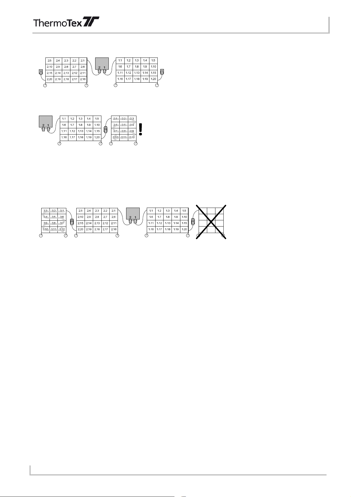
3.3 Examples
3.3.1 IN-SorTexx, one row of modules type “mounting set left”
3.3.2 IN-SorTexx, one row of modules type “mounting set right”
3.3.3 IN-SorTexx, two module rows
3.3.4 OUT-SorTexx, one row of modules type “frame left”
12
1.16
1.1
1.81.7
1.13
1.6
1.18
1.121.11
1.17
1.41.3
1.9
1.14
1.19
1.2 1.5
1.10
1.15
1.20 2.16
2.1
2.82.7
2.13
2.6
2.18
2.122.11
2.17
2.42.3
2.9
2.14
2.19
2.2 2.5
2.10
2.15
2.20
3.3.5 OUT-SorTexx, one row of modules type “frame right”
General information
GBSOTXBA_V(1).DOCX Page - 14
3.3.6 OUT-SorTexx, two module rows
3.3.7 OUT-SorTexx, incomplete shelf at end of row
The last shelf may have fewer compartments than the other shelves.
Please note that the compartments of this last shelf are not numbered in the same way as the other
compartments but according to the wiring sequence (i.e. S-shaped).
When connecting up two rows of modules, an incomplete shelf may only be placed at the end of the second row
of modules (on the left in the picture):
3.4 Acknowledgement
SorTexx offers an easy possibility for safeguarding error-free laundry sorting. To this end, the LED modules can
be equipped with buttons or reflection sensors as an option. On placing a garment in a compartment, the
operator actuates the corresponding button or sensor. In this way, the LED control unit can detect whether the
garment has been placed in the right compartment.
3.4.1 Waiting for acknowledgement (automatic)
With the setting “Wait for confirmation” (Wait for acknowledgement, see chapter 4.2.8), the LED control unit
waits after switch on a LED for the button or sensor of the corresponding compartment to be actuated.
Afterwards, the LED is switched off again automatically.
The optional signal transducer can be switched on when the wrong button or sensor is actuated (see 4.2.10).
3.4.2 Waiting for acknowledgement (PC software)
The PC software can perform this check as an alternative. In this case, the setting “Wait for confirmation” in
menu 2 must be disabled (see 4.2.8).
The PC software can check which buttons or sensors were actuated using the “Read button” and “Clear button”
commands.
Remarks:
•Every LED module has a button memory. This memory is set to 1 as soon as the button is pressed or the
light beam of the reflection sensor is interrupted.
•The LED modules check constantly whether the button (or sensor) is actuated, even if no LEDs of the
module are switched on.
•When a button memory has been set (value 1), this does not mean that the button or sensor is currently
actuated. It only means that the button or sensor has been actuated since the last time the button memory
was cleared.
•The “Read button” command scans the status of the button memory of a certain module and then clears the
button memory.

General information
GBSOTXBA_V(1).DOCX Page - 15
•In the broadcast version, the “Read button” command always only supplies the number of the first module
whose button memory is at 1. In doing so, this clears the button memory of this module. The “Read button”
command may have to be sent several times to encompass all modules that have detected a button being
pressed.
•It may be appropriate to clear the button memory of all modules first before switching on an LED and then
waiting for acknowledgement.
4 Operation
4.1 Switching on
To switch the device on, press the rocker switch at the bottom on the right. The display of the control unit now
lights up.
The control unit checks how many LED modules are connected up. The number of detected modules appears
after a few seconds For OUT-SorTexx, the display also shows the number of shelves in the system.
A few seconds later, the display shows “Ready”. The control can now receive and process commands.

Operation
GBSOTXBA_V(1).DOCX Page - 16
4.2 Menus
There are three different menu areas:
Menu 1: Choose language
Daily counter
Total counter
Operating hours counter
LED test
Button test
Beacon test
Menu 2: Rack type
Merge racks
Wait for confirmation
Use buffer memory
Alarm for wrong compartment
Alarm if shelf not confirmed
Automatic OFF
Alarm at terminal value
Counting direction
Terminal value
Start value
Send value automatically
Menu 3: MAC address
TCP port number
TCP timeout value
Use DHCP
IP address
Net mask
Gateway
Press the MENU button. The display shows "Menu 1 of 3", "Menu 2 of 3" and "Menu 3 of 3" in succession, at
intervals of approx. 2 seconds.
Hold the MENU button until you see the number of the required menu. Now release the button to activate the
corresponding menu area.
Now call up the individual menu points of the particular menu area. Press the "MENU" button briefly to move on
to the next point. After the last menu point, the system returns to the normal mode.
There is no communication with the PC while you are in a menu.
4.2.1 Choose Language
Use PLUS and MINUS to select the required language. The following languages are possible:
•German
•English
•French
After pressing MENU to confirm, the display now uses the chosen language.
4.2.2 Daily counter, total counter and operating hours
In the Day Counter sub-menu, the value of the Day Counter is shown, or the value since the last time the
counter was re-set. The Day Counter can be re-set using the “Reset" key, pressing the key for a short while.
The Total Counter sub-menu shows the total number counted.
The Operating Hours sub-menu shows the number of hours the machine has operated.

Operation
GBSOTXBA_V(1).DOCX Page - 17
4.2.3 LED test
Here you can test the LEDs of all connected modules. First the green LED of the first module lights up.
Use PLUS and MINUS to switch on the next or previous module.
Use F1 to change the colour between green, yellow and red.
Use F2 to switch on all modules automatically in succession.
4.2.4 Button test
This menu point only appears when the system is equipped with buttons or sensors.
When a button or sensor is actuated, the corresponding module lights up green and the number
of the module appears on the display.
4.2.5 Beacon test
This menu point only appears when the system is equipped with a signal transducer.
Use PLUS to switch the signal transducer on.
Use MINUS to switch the signal transducer off.
4.2.6 Rack type
This menu point only appears for OUT-SorTexx.
Use PLUS and MINUS to adjust the size of the connected shelves. Possible values:
•20 compartments
•24 compartments
•25 compartments
•30 compartments
4.2.7 Merge racks
This menu point only appears for OUT-SorTexx.
It can be used to merge all connected shelves logically to one single shelf. This shelf is shelf number 1.
Example:
Two shelves each with 20 compartments are merged logically into one shelf with 40 compartments.
Compartment numbers 1 to 10 are in the top line, 11 to 20 in the second line, etc.
4.2.8 Wait for confirmation
This menu point only appears when the system is equipped with buttons or sensors.
Every time after an LED is switched on, the control waits for the operator to place a garment in the
corresponding compartment and actuate the button or sensor.
The LED is then automatically switched off and the process moves on to the next compartment.
4.2.9 Use buffer memory
This menu point only appears when the “Waiting for confirmation” mode is active.
When the buffer memory is switched on, the control can accept further commands for switching LEDs on. After
a compartment has been acknowledged, the system automatically proceeds with the next command from the
buffer memory.
The buffer memory can take up to 10 commands.

Operation
GBSOTXBA_V(1).DOCX Page - 18
When the buffer memory is switched off, the control unit does not accept any further commands for switching on
modules while waiting for a compartment to be acknowledged.
4.2.10 Alarm signal for wrong compartment
This menu point only appears when the “Waiting for confirmation” mode is active and the system is equipped
with a signal transducer.
The signal transducer can be switched on when the system is waiting for a compartment to be acknowledged
and the button or sensor of a wrong compartment is actuated by the operator.
The signal transducer is switched off again when the button or sensor of the right compartment is
acknowledged.
4.2.11 Alarm if shelf not confirmed
This menu point only appears when the “Waiting for confirmation” mode is active and the system is equipped
with a signal transducer.
The signal transducer can be switched on when the system is waiting for a compartment to be acknowledged
and the next command to switch an LED on is already received.
The signal transducer is switched off again when the button or sensor of the current compartment is
acknowledged.
4.2.12 Automatic OFF
This menu point only appears when the “Waiting for confirmation” mode
is not active.
When automatic OFF is activated, before an LED is switched on, all other LEDs of the same colour are
automatically switched off. This does not affect LEDs of other colours.
In this way, maximum one green, one yellow and one red LED can be switched on at the same time in the
whole system.
When automatic OFF is not activated, several LEDs of the same colour can be switched on at the same time.
In this case, it is up to the controlling software to switch off any LEDs that are no longer needed. In addition, the
software has to ensure that the number of LEDs switched on at the same time does not exceed the permitted
value of 10.
4.2.13 Settings for operation mode ”Counting frame“
The following menus affect the operation mode “Counting Frame”:
- Alarm at terminal value
- Counting direction
- Terminal value
- Start value
- Send value automatically
4.2.14 Network settings
The following menus are used to select the network settings:
- MAC address
- TCP port number
- TCP timeout value
- Use DHCP
- IP address
- Net mask
- Gateway
4.3 F1 and F2
Press F1 on the LED control unit to switch off all LEDs that are currently switched on. Furthermore, this
switches the signal transducer off; it also clears the button memory of all modules together with the buffer
memory.
Operation
GBSOTXBA_V(1).DOCX Page - 19
Press F2 to cancel the current command.
5 Data protocol
5.1 Basic principles of communication
You need suitable PC software to communicate with the SorTexx system. This software sends commands to
SorTexx in order to perform certain actions. On receiving a command, the LED control unit sends an answer to
the PC.
The LED control unit also receives commands while waiting for an acknowledgement. If this is a command to
switch an LED on, it is written in the buffer memory (if this is activated). Otherwise, commands are executed
straightaway. The "Read button" and "Clear button" commands should not be used in this status because this
interferes with automatic button polling by the control unit.
5.2 Command
A command (from PC to LED control unit) always consists of 11 bytes:
0
1
2
3
4
5
6
7
8
9
10
Start
Shelf number
Compartment
number
Command
Parameter
Result
Stop
“<"” “000”…”999” “000”…”999” “1”…”9”, “Q”,
“R”, “S”, “T”,
“W”
“0”…“9”,
“A”…“F”
“0” “>”
In operation mode “Counting Frame”:
0
1
2
3
4
5
6
7
8
9
10
Start
Counter value
Counter number
C
ommand
Parameter
Result
Stop
„<“ „0000“…„9999“ „00“…„10“ „U“, „V“ „0“ „0“ „>“
A command usually addresses a certain module. This module is given a unique definition by the shelf number
and the compartment number.
Some commands can also be sent as broadcast, i.e. the command is executed by all modules. When the shelf
number or compartment number is “000”, the command is treated as a broadcast.
5.3 Answer
The answer (from LED control unit to the PC) always consists of 11 bytes. It has the same format as the
command data package:
0
1
2
3
4
5
6
7
8
9
10
Start
Shelf number
Compartment
number
Command
Parameter
Result
Stop
“<” “000”…“999” “000”…“999” “1”…“9, “Q”,
“R”, “S”
“0”…“9”,
“A”…“F”
“0”…“9”,
“A”…“C”
“>”
Byte 9 contains the result of the command:
•“0” = OK. This result is also sent after successful acknowledgement.
•“2” = time-out error when waiting for one certain module to answer
•“5” = wrong module answer
•“6” = unknown command
•“7” = wrong data package
•“8” = wrong shelf number or compartment number
•“9” = wrong parameter
•“A” = buffer memory is full
•“B” = waiting for acknowledgement (buffer memory is not active) => command ignored
•“C” = for LED switch-on command demanding acknowledgement: the command is executed or written in the
buffer memory. “OK” (“0”) is only reported after positive acknowledgement.
Data protocol
GBSOTXBA_V(1).DOCX Page - 20
•„D“ = Control unit is busy. You will receive this result when you are inside a menu.
For some commands, byte 8 (parameters) contains an additional value.
5.4 Start codes and end codes
By default the characters “<” and “>” are used as start and end codes.
Alternatively you can also use the following characters:
( )
[ ]
{ }
For generating the answer string, the control unit always uses the start and end codes that it found in the
correspondent command string.
5.5 Description of the commands
5.5.1 LEDs exclusive ON
Command byte “1”
Description Switch LED on and set flashing mode. Maximum one LED is switched on at the
addressed module. The remaining LEDs of the module are automatically switched off.
Parameter “0”: Switch LEDs off (note: switching an LED off does not constitute acknowledgement).
“1”: Continuous green
“2”: Continuous yellow
“3”: Continuous red
“5”: flashing green (fast)
“6”: flashing yellow (fast)
“7”: flashing red (fast)
“9”: flashing green (medium)
“A”: flashing yellow (medium)
“B”: flashing red (medium)
“D”: flashing green (slow)
“E”: flashing yellow (slow)
“F”: flashing red (slow)
Answer Result byte: see chapter 5.3
Broadcast possible Yes
5.5.2 LED cumulative ON
Command byte “2”
Description As above, but this command can be used to activate other LEDs without switching the
remaining LEDs of the module off.
If several LEDs are activated, they automatically light up alternately.
Parameter See above
Answer Result byte: see chapter 5.3
Broadcast possible Yes
5.5.3 LED cumulative OFF
Command byte “3”
Description As above, but this command switches off individual LEDs of a module
Parameter See above (note: switching an LED off does not constitute acknowledgement).
Answer Result byte: see chapter 5.3
Broadcast possible Yes
Table of contents


