1.5 Connecting the module
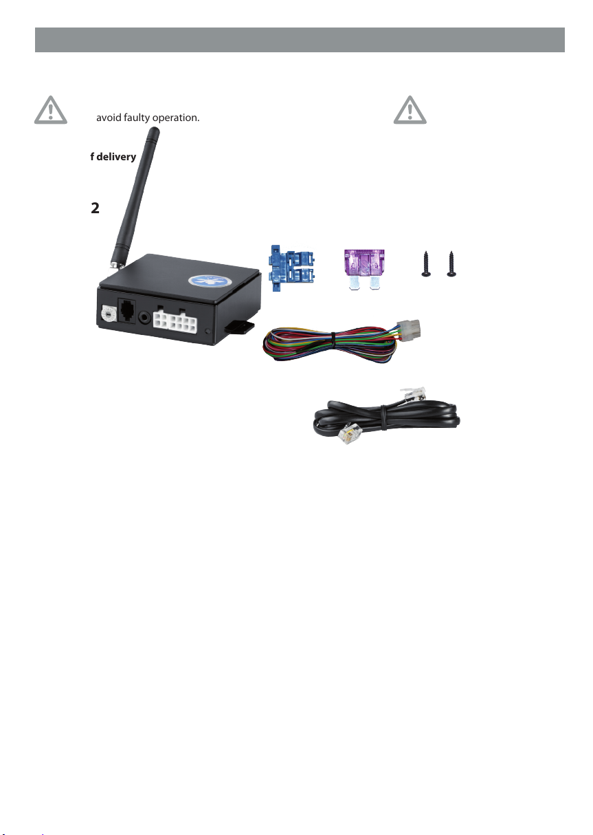
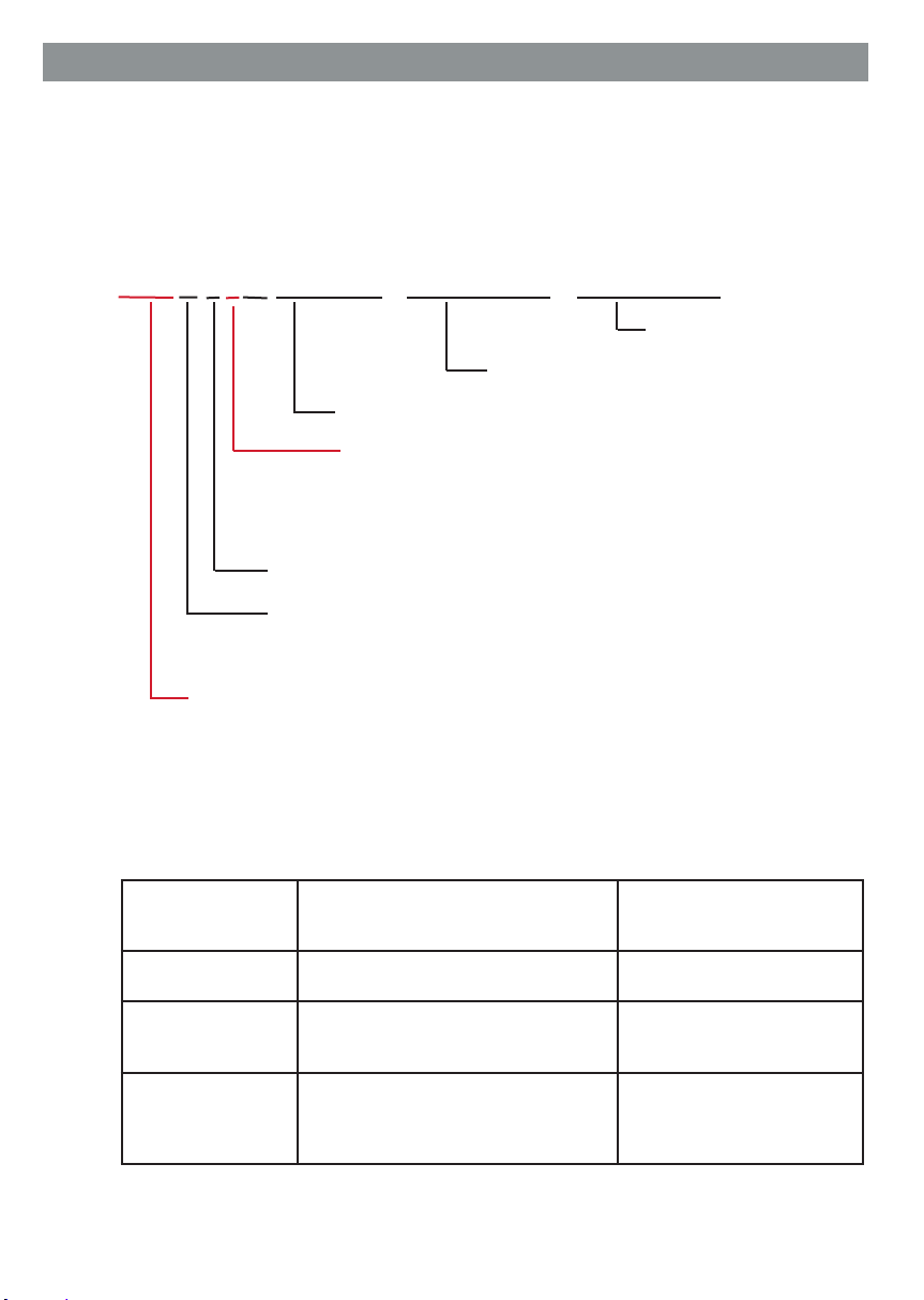
Connect pin 1 (black) and pin 8 (red) with the correct polarity (see 1.3) to a suitable
power supply (12 VDC). Protect the plus cable with the provided fuse.
Pins 2– 5 are measurement inputs that can be used to check voltages (0-30 V).
Depending on the mode, geofencing can also be activated via pin 3.
If necessary, connect WiPro III or WiPro“all in one” and Pro-nder using the included connecting cable.
!!! WiPro“all in one”and Pro-nder must be connected to the same battery !!!
Pin 6 and pin 7 are transistor outputs that supply 12 V and can withstand a load
of 500 mA. If consumers requiring more than 500 mA must be connected, a relay
must be used. Use a high-quality automotive relay with a recovery diode.
Overloads will void the warranty.
The outputs can be controlled as follows:
– Output switched on until the command is cancelled
– Output pulse (switched on for 1 second)
– Output switched on for freely specied time
Chapter 2.7 describes how to control the outputs via SMS
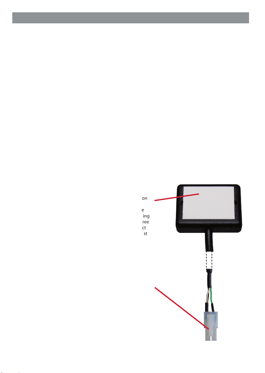
1.6 Installing the GPS receiver (optional)
The optional GPS receiver can be mounted at a location
inside the vehicle that is protected against sabotage,
using the already attached self-adhesive pad. The side
with the self-adhesive pad must face upward (receiving
side). Themounting location must be clean, dry and free
of grease. If the temperature is below 15 °C the contact
surface should be warmed rst. The receiving side must
be aligned as horizontally as possible.
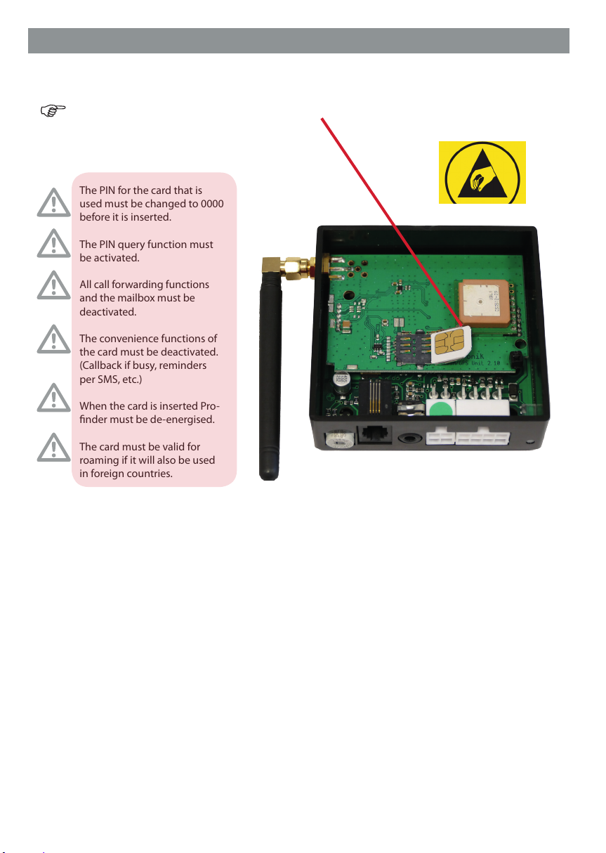
1.7 Connection of the GPS receiver
To connect the optional GPS receiver, Pro-nder must
bede-energised. Disconnect the main cable assembly
and then plug the GPS plug into the 4-pin connector for
the GPS receiver. Now you can re-connect the main cable
assembly.
To enable the GPS receiver to receive and save current satellite
data, the operating voltage must be greater than 13.5V for
at least 5 minutes after the installation. To achieve this, start
the vehicle. If the data is not saved, exact determination of
the position is not ensured. GPS reception must be ensured
(leaveany halls or roofed areas).
Pro-nder Manual Page 4