Time Gaurd MLSA360N User manual

360º Night Eye PIR
Light Controller
Model: MLSA360N
Installation & Operating Instructions

1
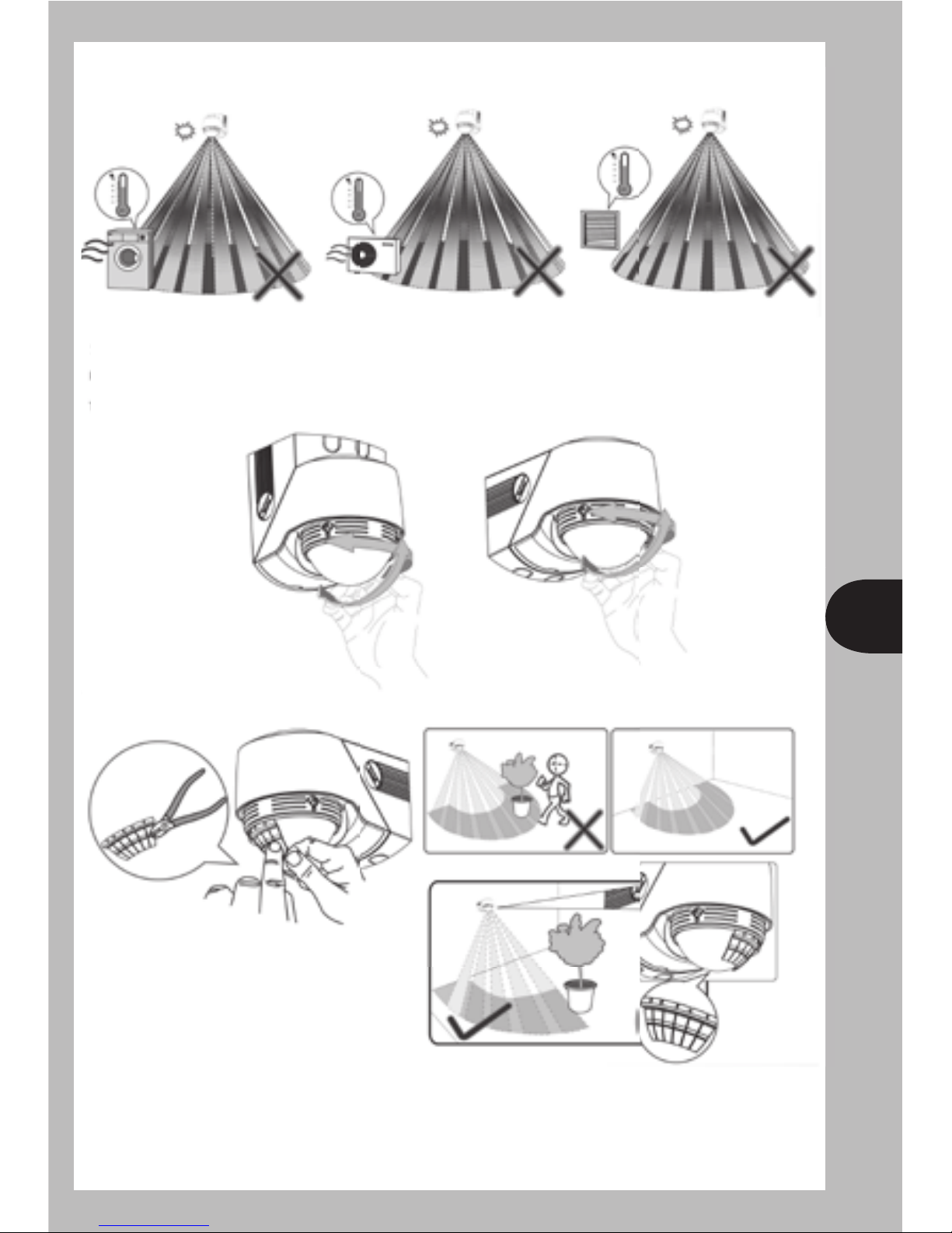
Motion Sensor Detection
Sensor Tilt Angle = 0º
Ceiling Mount Position Sensor Tilt Up 3º Sensor Tilt Down 30º
3º0º 30º
Perspective
View
5 metre5 metre
2.5m
1m
2
Sensor Head Adjustment
Lens Mask
Pan Adjustment: Left 45º, Right 45º.
Tilt Adjustment: Up 3º – To extend (Max. 8m) the forward detection.
Down 30º – To shorten the forward detection to 2.5m.
3
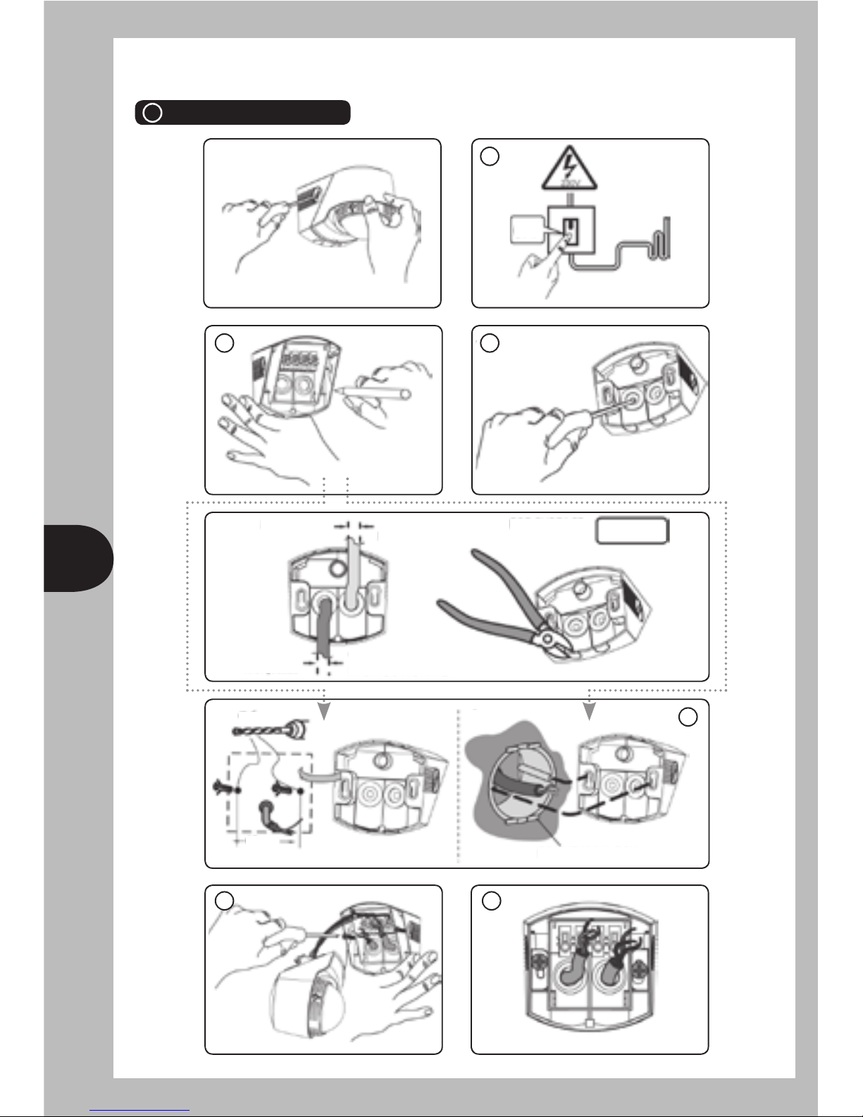
Mounting Insulation Steps
1 Wall Mounting
1
32
Round wall box
Ø6mm
60mm
4
65
For surface
mounting
OPTIONAL
Cable entry
from top x2
Cable entry from
bottom x2
Max. Ø11mm
Max. Ø11mm
OFF

4
2 Ceiling/Eave Mounting
3 External Corner Mounting
1
2
OPTIONAL
OFF
Cable entry
from rear x2
Max.
Ø11mm
60mm
Ø6mm
3 4
Cable entry
from
front x2
Max. Ø11mm
5 6 For
surface
mounting
1 2
3
Ø6mm
4 5
OFF
5
6
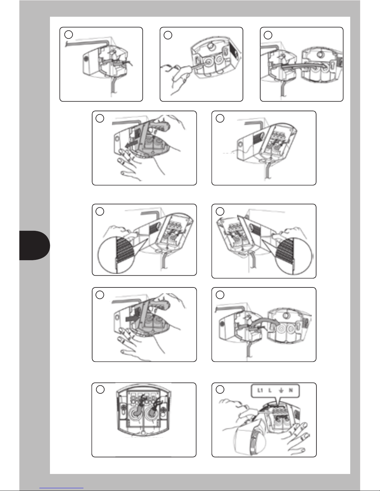
Wiring Connection Steps
Removing
8
9
1
3
10
2
4
21
7
(1) Power supply
(2) Wires connect to
lighting fixture
“Click”

6
Wiring Connection – (Single Lamp)
Wiring Connection – (Multiple Lamps)
5
“Click” “Click”
“Click” “Click”
34 43
ON
END
LIVE
LIVE
NEUTRAL
NEUTRAL
EARTH
EARTH
BROWN OR
RED
BROWN OR
RED
BLUE OR
BLACK
BLUE OR
BLACK
GREEN/YELLOW OR BARE
COPPER WIRE
GREEN/YELLOW OR BARE
COPPER WIRE
7
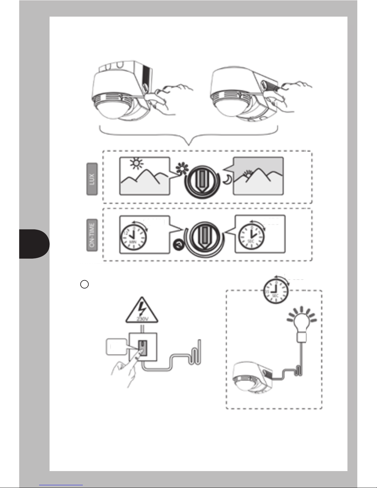
Testing & Operation
Adjustment:
Can be adjusted by using a flat head screwdriver.
Walk Testing
35 sec
5 sec
12 min
End
1
ON

8
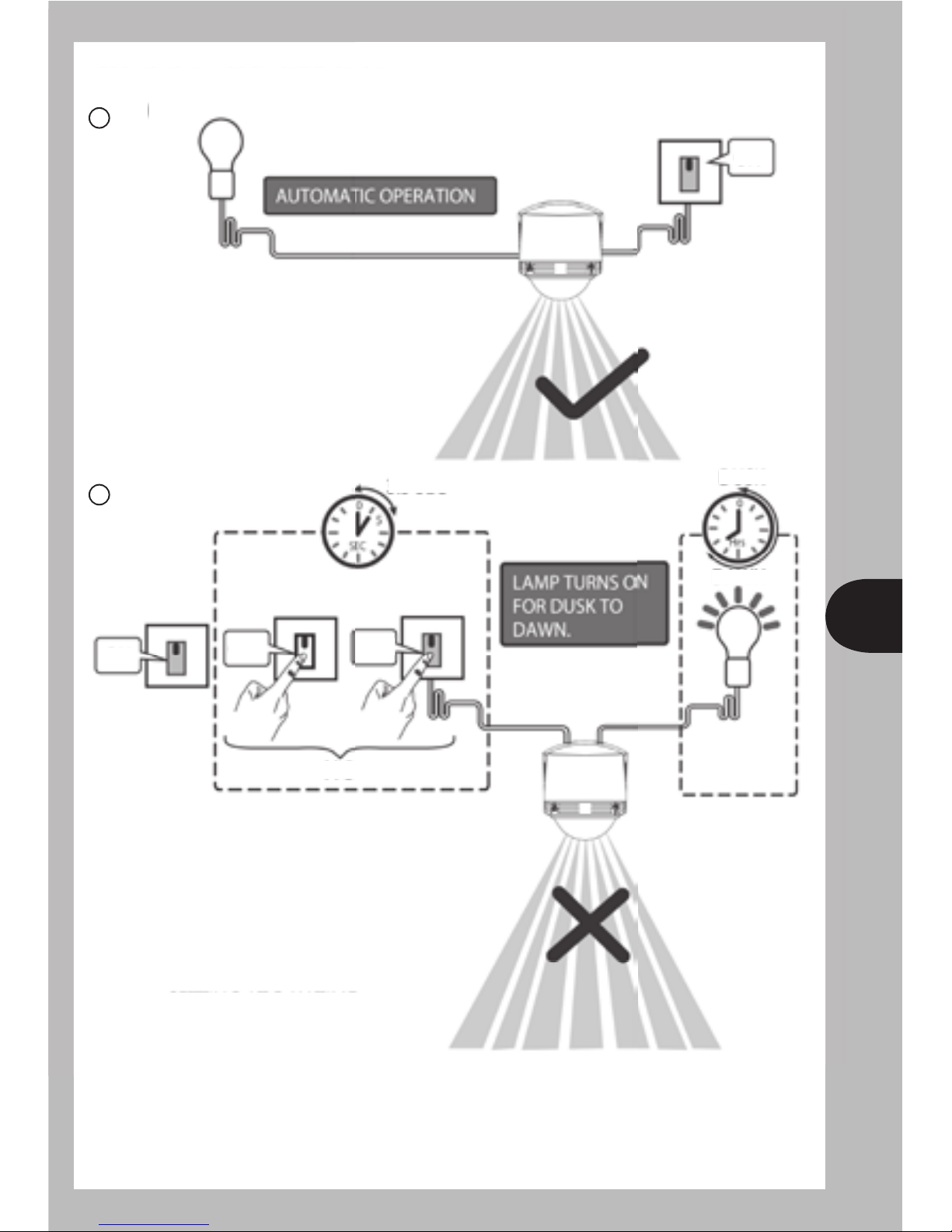
Manual Override Operation
For permanent OFF.
MIN. SUN.
2
3
OFF
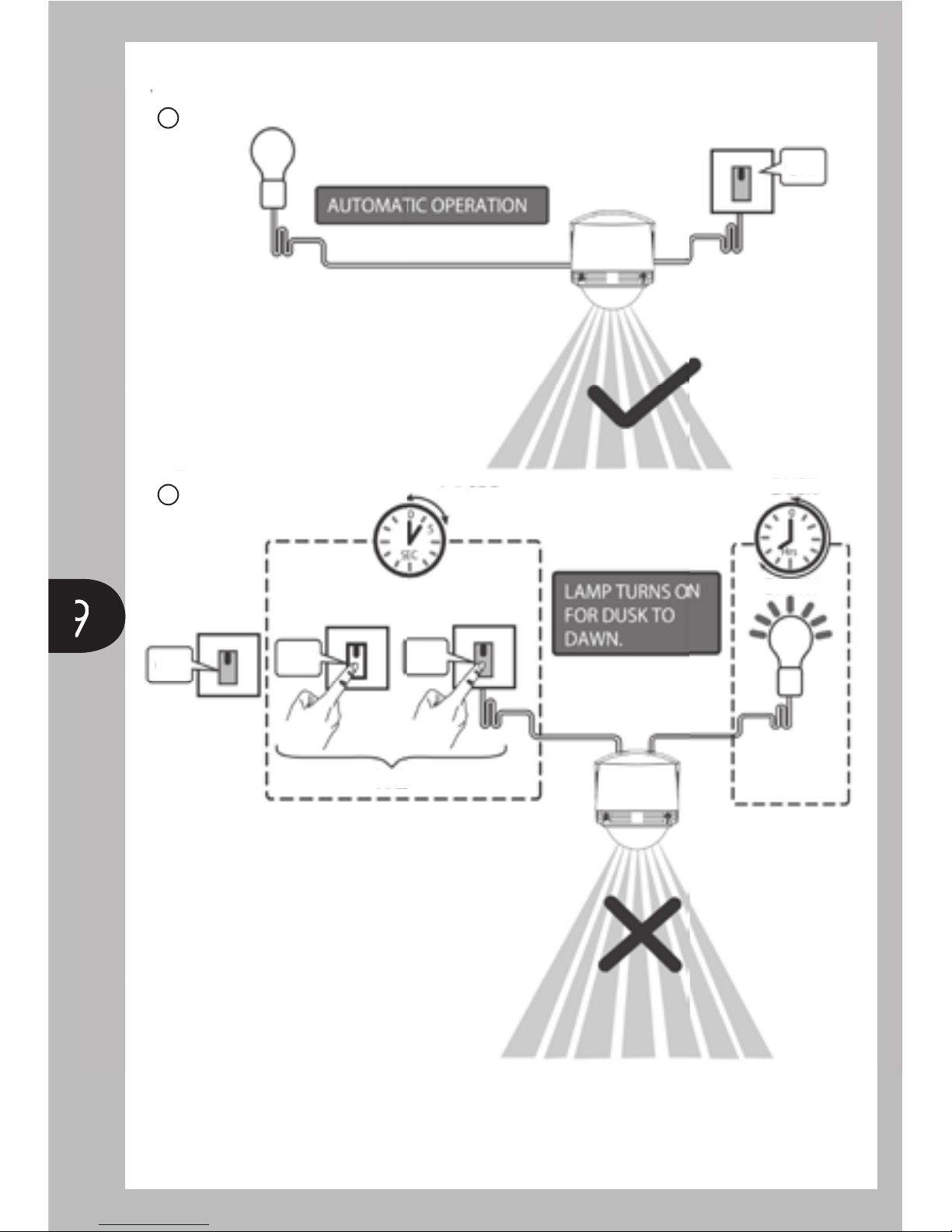
9
9
For Pulse Manual Operation (Manual Mode) Light Turn ON.
2.5 sec
Setting at day time,
Operate at night time.
Pulse Manual Operation mode will
only operate for 1 night, then after will
revert back to auto mode.
Dusk
Dawn
x2
1
2
OFF
ON ON
ON
10
For Holiday Mode Light Turn ON.
3.5 sec
Setting at day time,
Operate at night time.
Dusk
Dawn
1
2
ON OFF
X3
ON
ON
11
11
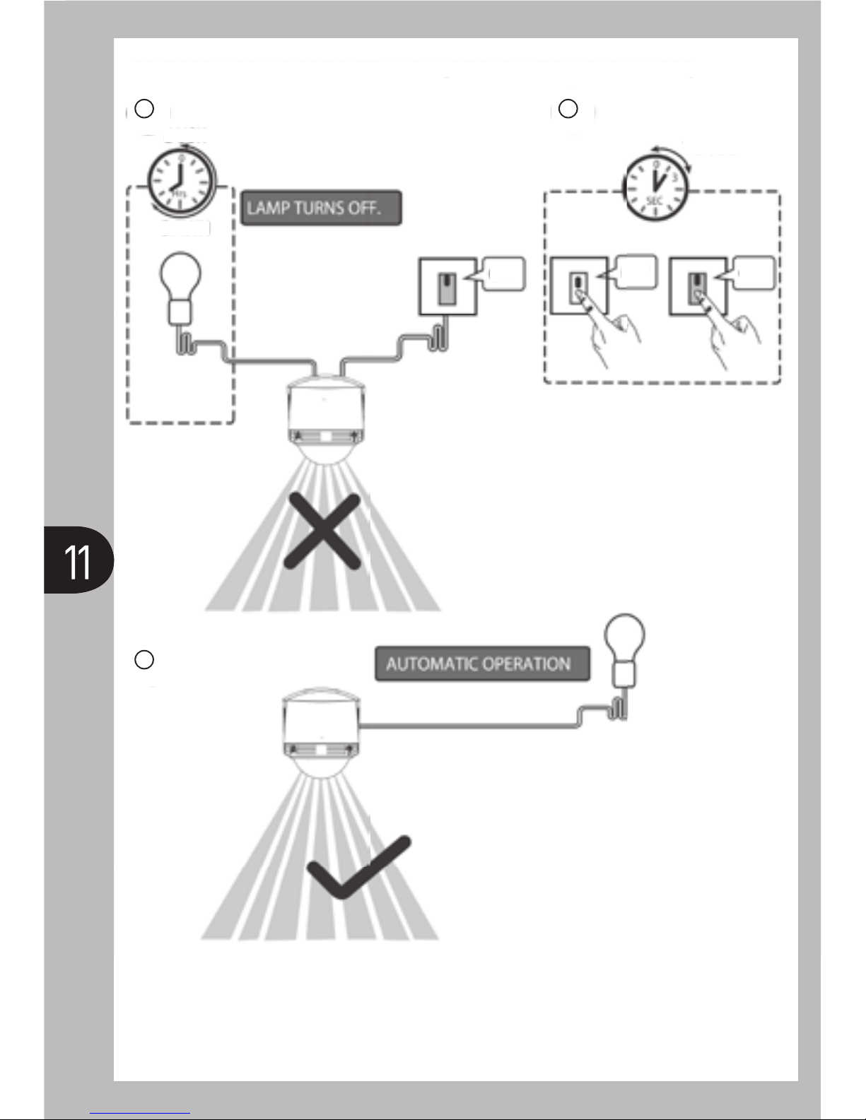
Revert to Automatic Operation Mode (OFF PMO Mode / Holiday Mode).
Dusk 1.5 sec
Dawn
1
3
2
ON ONOFF

12
1. General Information
The unit utilises passive infrared technology to detect heat radiation from moving
human bodies. Upon detection, the lamp will illuminate for a user-determined
time period.
An integral daylight sensor ensures night-only operation.
2. Parts Included
• PIR Sensor Unit.
• Instruction manual. Please keep safe for future reference.
• Accessory Pack.
• Corner mount bracket.
3. Tools & Parts Needed
• 3 core cable
• Electric/hand-held drill & bits.
• Terminal or Electricians screwdriver.
• Large slotted/philips screwdriver.
• Wire cutters.
Lighting loads connected must not exceed maximum 2000W filament
or 110W fluorescent/low energy lighting. It is not recommended to
use this product with discharge lighting. Do not attempt to install
during wet weather, if you are suffering from nausea or dizzy spells
or on medication with similar side effects.
If in any doubt, consult a qualified tradesperson or electrician.

13
4. Selecting the Location
Please note:- PIR sensors are not suitable for installation in glass
enclosures such as porches or conservatories. PIR sensors do not
detect through glass and need a clear unobstructed view of intended
detection area.
The motion detector has a number of detection zones, at various vertical and
horizontal angles as shown. A moving human body needs to cross/enter one
of these zones to activate the sensor. The best all-round coverage is achieved
with the unit mounted at the optimum height of 1.8m.
Careful positioning of the sensor will be required to ensure optimum
performance. See detailing detection range and direction. The sensor is
more sensitive to movement ACROSS its eld of vision than to movement
directly TOWARDS.
Therefore position the unit so that the sensor looks ACROSS the likely approach
path. Avoid positioning the sensor where there are any sources of heat in the
detection area (extractor fans, tumble dryer exhausts etc). Reective surfaces
(ie pools of water, conservatories or white-painted walls) and overhanging
branches may cause false activation under extreme conditions. During extreme
weather conditions the motion sensor may exhibit unusual behaviour. This does
not indicate a fault with the sensor. Once normal weather conditions return, the
sensor will resume normal operation.
Light Pollution
To reduce the risk of light pollution, consider the following when installing
the unit.
Position the unit to ensure that the light emitted does not encroach onto
neighbouring properties. Angle the oodlight downward to focus the illumination
onto the ground, not into the sky. Consider using a lower wattage bulb to save
energy and reduce high light output if not required.
14
5. Installation
After choosing a suitable location (see previous section) install the unit
as follows:
The unit is suitable for connection to a 230 V ac 50Hz electricity supply. It is
suggested that 3-core round exible cable of 1mm2is used. An internal switch
should be installed to switch the power to the unit ON & OFF. This allows the
sensor to be easily switched off when not required or for maintenance purposes.
Slide the mounting plate in a downward direction to release.
Mark the position of the tting holes.
Drill the holes. Insert the rawl plugs into the holes.
Pierce & pass the cable through the grommet before proceeding.
It is recommended that the grommet is pierced with a screwdriver to ensure
a better seal.
Attach the mounting plate to the wall using suitable screws. Do not overtighten
the mounting screws as this could damage the mounting plate.
Connection
Connect the mains supply cable to the terminal block on the unit as follows
(see connection diagram):
NEUTRAL (Blue) N
EARTH (Green/Yellow)
LIVE (Brown) L
Connect the cable from the lighting load to the terminal block on the unit as
follows (see connection diagram):
NEUTRAL (Blue) N
EARTH (Green/Yellow)
LIVE (Brown) L’
IMPORTANT
Switch off the electricity at the fuse box by removing
the relevant fuse or switching off the circuit breaker
before proceeding with the installation.

15
6. Operation and Testing
Walk Testing Procedure
The sensor will rotate from left to right, and tilt forward or backward.
The small arrow on the underside of the sensor indicates the direction of the
main detection area.
Adjust the sensor to point in the desired direction.
Set the two adjustment controls to the following positions:
TIME – Fully anti-clockwise
DUSK – Fully clockwise
The unit will now operate during daytime as well as at night, illuminating the
lamp for approx. 5 seconds each time. This allows testing to be carried out to
establish the best position for the sensor.
The lamp will immediately illuminate as the unit goes through its “warm-up”
period. After approximately 1 – 2 minutes the lamp will extinguish. Try to remain
outside the detection area during the warm-up period.
Walk across the detection area approx. 2.5 metres from the unit. As you cross
a detection "zone" the lamp will illuminate. Now stand still until the lamp
extinguishes (this should take approx. 5 seconds).
Start moving again. As you cross each "zone" the lamp will illuminate.
Repeat the above, walking at various distances and angles to the unit. This will
help you to establish the detection pattern.
If the detection area is too small for your requirements, try angling the sensor
head up. This will increase the coverage distance. Angling the head downwards
will reduce the range should a smaller coverage area be required.
Ensure that all connections are secure.
For details of override connections, please see connection diagram.
Re-afx the terminal block back onto the wall mounting plate.
Slide the main body back onto the mounting plate then pull in a downwards
direction so that it is fully engaged with the mounting plate.
Secure the unit by replacing the screw on the underside.

16
Setting Up For Automatic Operation.
When walk tests are complete, the unit can be switched to automatic operation:
The TIME setting controls how long the unit remains illuminated following
activation & after all motion ceases. The minimum time (fully anti-clockwise)
is approx. 5 seconds, whilst the maximum time (fully clockwise) is approx.
12 minutes. Set the control to the desired setting between these limits.
The DUSK control determines the level of darkness required for the unit to
start operating.
The setting is best achieved by the procedure below:
Set the DUSK control knob fully anti-clockwise. Wait until darkness falls.
When the ambient light level reaches the level of darkness at which you wish
the lamp to become operative (ie. At dusk), SLOWLY rotate the control in a
clockwise direction until a point is reached where the lamp illuminates.
Leave the control set at this point.
At this position, the unit should become operative at approximately the same
level of darkness each evening. Observe the operation of the unit. If the unit is
starting to operate too early (ie. when it is quite light), adjust the control slightly
anti-clockwise. If the unit starts to operate too late (ie. only when it is very dark),
adjust the control slightly clockwise.
Continue to adjust until the unit operates as desired.
For Manual and Holiday Modes see the diagrams.

17
3 Year Guarantee
In the unlikely event of this product becoming faulty due
to defective material or manufacture within 3 years of the
date of purchase, please return it to your supplier in the
first year with proof of purchase and it will be replaced free
of charge. For years 2 and 3 or any difficulty in the first year telephone the
helpline on 020 8450 0515.
first year with proof of purchase and it will be replaced free
If you experience problems refer to Troubleshooting Guide.
If problems still exist, do not immediately return the unit to store.
Telephone the Timeguard Customer Helpline
020 8450 0515
Quali ed Customer Support Co-ordinators will be on-line
to assist in resolving your query.
7. Technical Specifi cations
Detection Range
Detection Angle
Power Supply
Maximum Switchable Load
Time On Adjustment
Dusk Level Adjustment
Environmental Protection
EC Directives
Up to 12 metres
360º
230 V AC ~ 50Hz
Incandescent: 2000W
CFL: 110W
Fluorescent tube: 600W
Do not use with discharge lighting ie SON or HID
5 seconds – 12 minutes
Day & night or night only operation
IP45 (suitable for outdoor use)
Conforms to 73/23/EEC, 89/336/EEC

18
8. Troubleshooting Guide
Problem
Lamp stays ON all the time
at night.
PIR keeps activating for no
reason / at random.
PIR sensor will not operate
at all.
The PIR sensor will not
operate at night.
Unit activates during the
daytime
PIR coverage is poor/sporadic
Detection range varies from
day to day
Solution
The unit may be suffering from false activation. Cover the sensor
lens completely with a thick cloth. This will prevent the sensor from
"seeing" anything. If the unit now switches off after the set time
duration and does not reactivate, this indicates that the problem
was caused by false activation. The problem may be solved by
slightly adjusting the direction/angle of the sensor head
(see section 4).
You may not be allowing the unit time to complete it’s warm-up
period. Stand well out of the detection range and wait (the warm-
up period should never exceed 12 minutes).
Occasionally, winds may activate the sensor. Sometimes passages
between buildings etc. can cause a "wind tunnel" effect.
Ensure the unit is not positioned so as to allow detection of cars/
people using public thoroughfares adjacent to your property.
Check that the power is switched ON at the circuit breaker/internal
wall switch.
Turn OFF the power to the unit and check the wiring connections as
per the diagram (see previous section 3).
Ensure no connections are loose.
Check the lamp. If the lamp has failed, replace. Ensure that the
lamp is seated correctly in the lampholder.
The level of ambient light in the area may be too bright to allow
operation at the current DUSK setting. During the hours of
darkness, adjust the DUSK control slowly clockwise until the lamp
illuminates. Refer to section 4 for more details.
The level of ambient light in the area may be too dark for the
current DUSK setting. During daylight, adjust the DUSK control
slightly anti-clockwise. When the lamp load extinguishes, enter the
detection area. If the PIR still activates, the setting is still too high.
Repeat the above procedure until the PIR does not activate when
you enter the detection area. Refer to section 4 for more details.
Unit may be poorly located. See section 2 – ‘Selecting The Location’
and re-locate the unit.
PIR sensors are inuenced by climatic conditions. The colder
the ambient temperature, the more effective the sensor will be.
You may need to make seasonal adjustments to the sensor head
position to ensure trouble free operation all year round.

Designed in the U.K. 67-058-421
Timeguard Limited.
Victory Park, 400 Edgware Road,
London NW2 6ND
Sales Offi ce: 020 8452 1112
or email csc@timeguard.com
For a product brochure please contact:
Zerofour – September 2011
or email helpline@timeguard.com
HELPLINE
020 8450 0515
Table of contents


