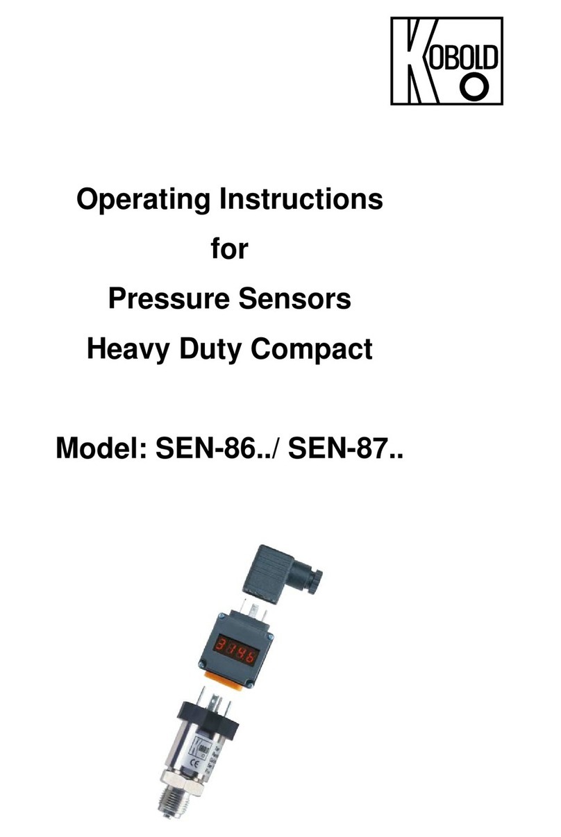
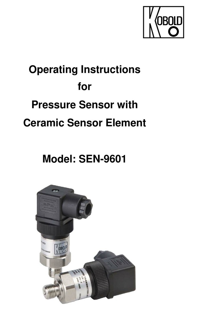
Kobold SEN-33 Series User manual

Operating Instructions
for
Pressure Sensors
Model: SEN-3

SEN-3
page 2 SEN-3 K04/0322
1. Contents
1.Contents ........................................................................................................ 2
2.Note .............................................................................................................. 3
3.Regulation Use ............................................................................................. 3
4.Operating Principle ........................................................................................ 3
5.Instrument Inspection .................................................................................... 3
6.Mechanical Connection ................................................................................. 4
7.Electrical Connection .................................................................................... 5
8.Trouble Shooting ........................................................................................... 6
9.Technical Information .................................................................................... 7
10.Maintenance ................................................................................................. 7
11.EU Declaration of Conformance ................................................................... 8
Manufactured and sold by:
Kobold Messring GmbH
Nordring 22-24
D-65719 Hofheim
Tel.: +49(0)6192-2990
Fax: +49(0)6192-23398
E-Mail: [email protected]
Internet: www.kobold.com

SEN-3
SEN-3 K04/0322 page 3
2. Note
Please read these operating instructions before unpacking and putting the unit
into operation. Follow the instructions precisely as described herein.
The instruction manuals on our website www.kobold.com are always for currently
manufactured version of our products. Due to technical changes, the instruction
manuals available online may not always correspond to the product version you
have purchased. If you need an instruction manual that corresponds to the
purchased product version, you can request it from us free of charge by email
([email protected]) in PDF format, specifying the relevant invoice number and
serial number. If you wish, the operating instructions can also be sent to you by
post in paper form against an applicable postage fee.
The devices are only to be used, maintained and serviced by persons familiar
with these operating instructions and in accordance with local regulations
applying to Health & Safety and prevention of accidents.
By usage in machines, the measuring unit should be used only when the
machines fulfil the EC-machine guidelines.
3. Regulation Use
Any use of the Pressure Sensors Model: SEN-3 which exceeds the
manufacturer’s specification may invalidate its warranty. Therefore, any resulting
damage is not the responsibility of the manufacturer. The user assumes all risk
for such usage.
4. Operating Principle
Pressure sensors transmit the mechanical quantity pressure into an electrical
output signal. The media’s which are in contact with the instrument should be
chemically compatible with the instrument materials used. Do not use standard
sensors in hazardous areas and for oxygen applications.
5. Instrument Inspection
Instruments are inspected before shipping and sent out in perfect condition.
Should the damage to a device be visible, we recommend a thorough inspection
of the delivery packing. In case of damage, please inform your parcel service /
forwarding agent immediately, since they are responsible for damages during
transit.
Scope of delivery:
Pressure Sensors model: SEN-3
SEN-3
page 4 SEN-3 K04/0322
6. Mechanical Connection
The places where pressures are taken should be prepared according the
following specifications for the screw-in threads. This is very important for
pressure sensors with front diaphragm, because otherwise the diaphragm could
be damaged. For sealing, please use sealing discs acc. DIN 16258 or profile
washers. The maximum initial tension depends on the material, the shape of the
used sealing and the mechanical connection of the pressure sensor.
The given tensions should not be exceeded.
50 Nm for pressure sensors with metallic sealing cone (hereby, there could be
for small measure ranges a deviation of the zeropoint of maximum 1%. This
deviation could be adjusted, with the zero point potentiometer see chapter
"Maintenance").
80 Nm for pressure sensors with pressure connection acc. DIN 16288,
and/or flash front diaphragm with O-ring.
There should be no vibrations and/or no radiation of heat near the mounting
position of the sensors. Please pay attention that the giving operating limits are
not exceeded. After the mechanical and electrical connection the sensor is ready
for operation.

SEN-3
SEN-3 K04/0322 page 5
7. Electrical Connection
Ensure that the power is disconnected during connection of the cable.
The electrical connection is made either via plug and pin or by cable.
The exact wiring scheme is shown on the sketches hereafter or at the type
plate of your sensor.
Attention! to the different wire systems.
Meaning of the different connector markings
UB+ positive pole of the supply voltage
OV negative pole of the supply voltage
S+ positive pole of the output signal
S- negative pole of the output signal
Shielding Cable protection enclosure-earth
Pressure sensors for relative pressures with cable output are equipped with an
atmospheric pressure compensation cable. Please take this into account if you
want to extend the cable. The relative pressure sensor with pressure ranges up to
25 bar are vented due to a venting sealing between housing and plug.
The sensor could be supplied with an unregulated DC source with the specified
voltage range. The minimum supply voltage for pressure sensors with current
output, should be the minimum UB plus the minimum voltage, which is needed to
operate the external indicator or input device:
Current output
2-wire system 3-wire system
Output signal 4...20 mA 0...20 mA
Supply voltage UB= 10 ... 30 VDC
Permissible load RA[Ohm] = (UB[V] - 1 0 V) / 0,02
A
Wiring scheme see scheme
Voltage output
3-wire system 3-wire system
Output signal 0...5 V 0...10 V
Supply voltage UB = 10…30 VDC UB = 14…30 VDC
Permissible load RA >5 kOhm RA >10 kOhm
Wiring scheme see scheme

SEN-3
page 6 SEN-3 K04/0322
8. Trouble Shooting
Trouble Possible
r
eason What's to do
No signal no supply voltage
broken wire
Check your power supply and
wiring. lf necessary replace
defective parts
Sensor has been wired
improperly
Check the wiring according to
the sketches and adjust wiring if
necessar
y
.
No pressure Check
y
our tubin
g
, valves open?
Defective electronics
caused by excessive supply
volta
g
e or b
y
external volta
g
e
Return sensor to us for repair
Unchan
g
ed si
g
nal b
y
Pressure port is blocked Clean the pressure por
t
changing pressure Defective electronics caused by
excessive supply voltage or by
external volta
g
e
Return sensor to us for repair
Pressure sensor over
pressurized
Return sensor to us for repair
To high, even on changing
pressure unchanged signal
Defective electronics caused by
excessive supply voltage or by
external volta
g
e
Return sensor to us for repair
Span of signal too small Supply voltage too low or loop
resistance too hi
g
h
Adjust supply voltage to
overcome loop resistance
Span adjustment potentiometer
dere
g
ulated
Recalibrate sensor

SEN-3
SEN-3 K04/0322 page 7
Trouble Possible
r
eason What's to do
Zero Signal too low Zero adjustment potentiometer
dere
g
ulated
Recalibrate sensor
Zero signal too high Zero adjustment potentiometer
dere
g
ulated
Recalibrate sensor
Mechanical damage Recalibrate sensor
Return to us for repair
Output signal non linear Mechanical damage Recalibrate sensor
Return to us for repair
9. Technical Information
Sensor element: Model: SEN-32... Piezoresistive
Model: SEN-33... Thin film
Material housing: Stainless steel 1.4301
Material wetted parts: Stainless steel 1.4571 and 1.4542
Accuracy: 0.1; 0.25; 0.5 or 1% of FS (depending on type)
Repeatability: ± 0.05% of FS
(± 0.03 % of FS for SEN-3382)
Stability/year: ± 0.2 % of FS (under reference conditions)
(± 0.1 % of FS for SEN-3382)
Overload limit: 16 bar 3.5-times (3-times for SEN-3382)
600 bar 2-times
600 bar 1.5-times
Temperature comp. Range: 0...+80 °C
Effect of temperature: see data sheet
Protection: IP 65
Temperature ranges: store room: -40...+100 °C
(-40...+85 °C for SEN-3382)
Measured media: -30...+100°C
(-20...+80 °C for SEN-3382)
Ambient: -20...+80 °C
Response time: 1 ms (within 10-90% of FS)
10. Maintenance
The pressure sensors described in this manual are maintenance free! They do
not contain any components which may be repaired or exchanged locally.
Repairs are only possible in our factory.

SEN-3
page 8 SEN-3 K04/0322
11. EU Declaration of Conformance
We, KOBOLD Messring GmbH, Hofheim-Ts, Germany, declare under our sole
responsibility that the product:
Pressure Sensor Model: SEN-3...
to which this declaration relates is in conformity with the standards noted below:
EN 61326-1:2013
Electrical equipment for measurement, control and laboratory use - EMC
requirements - Part 1: General requirements
EN 61326-2-3:2013
Electrical equipment for measurement, control and laboratory use - EMC
requirements - Part 2-3: Particular requirements - Test configuration, operational
conditions and performance criteria for transducers with integrated or remote
signal conditioning
Also, the following EC guidelines are fulfilled:
2014/30/EU EMC Directive
2011/65/EU RoHS (category 9)
2014/68/EU PED
PS200 bar; module A, pressure accessories
Hofheim, 09. May 2019
H. Peters M. Wenzel
General Manager Proxy Holder
This manual suits for next models
10
Table of contents
Other Kobold Accessories manuals

Kobold
Kobold AFK-A User manual

Kobold
Kobold DRG-11 User manual

Kobold
Kobold OPT Series User manual

Kobold
Kobold KET User manual

Kobold
Kobold LTS-A User manual

Kobold
Kobold Heinrichs TM User manual

Kobold
Kobold HND-PS19 PS33 Series User manual

Kobold
Kobold NWP-1405 Series User manual

Kobold
Kobold Heinrichs HPC Series User manual

Kobold
Kobold PMP User manual
Popular Accessories manuals by other brands

ABB
ABB ADS420 manual

S+S Regeltechnik
S+S Regeltechnik HYGRASGARD ESFF Series Operating Instructions, Mounting & Installation

Lippert Components
Lippert Components Solera Classic Awning Replacement

SILLA
SILLA PRISM SOLAR S Quick setup guide

Naxa
Naxa NF-588 instruction manual

GF
GF Signet 3-2630 Series manual