TKR Group PG 5-8 User manual

81 29 2 208 034
Granule jet blasting device
PG 5–8
Owner‘s Manual
Translation of the original instructions

This instruction manual is protected by copyright. No use outwith the strict limitations of copy-
right legislation without the consent of the manufacturer is permitted, this rendering the offen-
der liable to criminal prosecution. This applies likewise for the extraction of individual illustrations
and the use of texts in extract form.

3
1. Information regarding this manual 4
2. Permitted operators 4
3. Pictograph key 5
1. Use for intended purpose 6
2. Danger sources 6
3. Safety devices on the equipment 8
4. Safety measures at the installation site 10
1. Unpacking the device 11
2. Identification and description of the device
components 11
3. Device components 12
4. Technical Data 14
1. Operation of the granule jet blasting device 15
2. Granule jet blasting device
preparation and connection 16
3. Filling with blasting material 18
4. Connect vacuum adapter to vacuum cleaner 22
5. Attach blasting lance to handle 23
6. Starting the cleaning process 24
7. Blasting 25
8. Cleaning the inlet valves and the inlet channel 26
9. Taking the device out of service 28
1. Maintenance / cleaning 29
2. Spare parts and accessories for the PG 5–8
granule jet blasting device 32
3. Warranty conditions 34
4. EU Declaration of Conformity 35
1.
2.
3.
4.
5.
3
Other languages, spare parts
and accessories:
www.tkr-service.com

44
1.1 Information regarding this manual
Legislation stipulates that users must be trained in the use of
manually operated blasting equipment.
The granule jet blasting device corresponds with the state of
technology. To ensure that the equipment operates safely, it
must be operated in a proper and safe manner.
In the interests of quality assurance, we reserve the
unrestricted right to proceed to technical modifications arising
out of further developments in technology and product
improvements, without prior notification.
Read the instruction manual carefully before using the device.
All handling necessary to ensure correct operation is descri-
bed in the instruction manual.
No work methods other than those expressly approved by the
manufacturer may be used.If faults occur during operation of
the device, they must be remedied by trained experts only.
The owner/operator of the machine must make the ope-
rating instructions available to the operator and ensure
that they have been read and understood. Only then
may the operator start up the device.
Note
State-of-the-art
Technical
modifications
Read
instruction
manual
Handling
Faults
1.2 Permitted operators

55
1.3 Pictograph key
Several sections of these operating instructions are marked
with internationally recognised warning signs, danger notes and
general prohibition signs. Please comply with all notes and safety
rules!
The individual pictographs are explained in the following.
Instruction manual
general instructions
Observe the general
instructions
Wear face mask
Wear hearing protection
Wear gloves
Wear protective clothing
Warning
General source of danger
Warning
System under pressure
Risk of hearing damage
Warning - noise with high sound
pressure level
Follow all in-
structions and
safety rules
Please note the following.
Arrow to clarify
pressing together
Arrow indicating direction
For further information
see chapter...
Audibly engage
Shorten
Blow out with air
Clean with air/granule mixture

66
2.1 Use for intended purpose
The granule jet blasting device complies with the machi-
nery directive 98/37 EC and is used for processing the
surface of metal using a grainy blasting material, that is
blasted onto the surface that is being processed. The
blasting material is transported using compressed air.
The GP 5-8 granule jet blasting device is used for removing
carbonized material from the inlet channel and valves of combu-
stion engines.
The jet blasting device may only be operated in combination
with the vacuum adapters that are approved for the relevant
engine type and a vacuum cleaner with sufficient suction po-
wer.
Unauthorised modifications or changes to the device are not
permitted for safety reasons.
The granule jet blasting device is safe if used for its correct pur-
pose.
If it is used incorrectly and/or negligently by untrained
personnel, serious injuries could be caused by the es-
caping granules.
The blasting probe must never be used without the
provided vacuum adapter and vacuum equipment with
adequate power.
Never direct the blasting probe at persons or look into
the opening of the blasting probe. Risk of injury!
2.2 Danger sources
7
The device must only be operated using hoses that are appro-
ved for the purpose of use and the operating pressure of the
device.
The device may only be used by trained personnel.
Never throw or drop the granule jet blasting device.
The granule jet blasting device may only be used at ambient
temperatures of between 5 °C and 50 °C.
The granule jet blasting device must not be used in potentially
explosive areas!
The device must never be operated without suitable protective
clothing, such as a safety mask and safety shoes. Risk of injury!
Before carrying out maintenance or cleaning work and
always before filling the device with granules, the com-
pressed air supply must be disconnected and the device
depressurised.
The granule jet blasting device may only be operated with com-
pressed air.
The granule jet blasting device must always be set up on
a level surface or the floor of the workshop. The device
must not be set up on tables, workbenches or other ob-
jects. (Container is under pressure!)
Hoses and supply lines must be routed in such a way that they
cannot be damaged or become trapped! The hoses must also
be routed in a way that prevents people from tripping over
them.
Chapter 5.1
Chapter 2.4
2.3.1 2.3.2
8
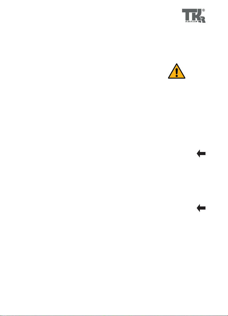
2.3 Safety devices on the equipment
There is a 3-way ball valve on the granule container that ap-
plies compressed air to the container and the control system in
the operating position.
In the „Off“ position the container and the control system are
depressurised.
Item B:
work item
Item A:
relieve
Fig. 2.3.1
Fig. 2.3.2
If a control function fails, the device must be taken out
of service immediately and repaired by a trained expert!
There is a pressure gauge on the granule container. The
maximum operating pressure of the device may never
exceed 8 bar. A safety valve is installed on the granule
container that controls the maximum operating pressu-
re of the device. The valve opens at pressure of approx.
8.5 bar.
7
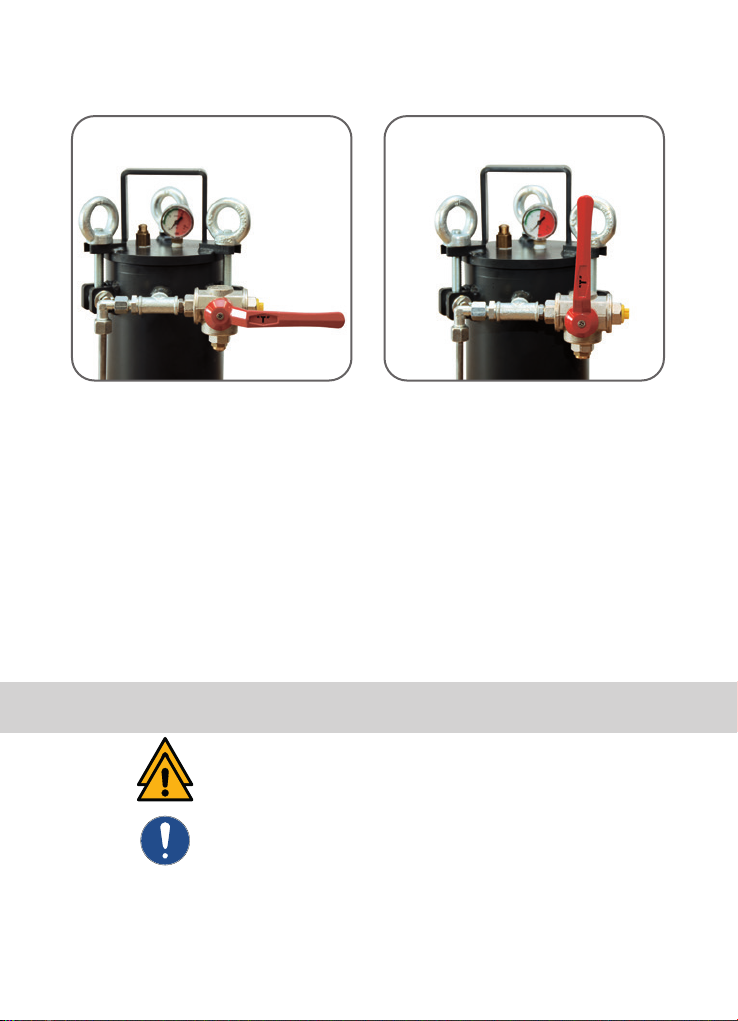
2.3.3
9
There is a 2-way ball valve on the handle of the blasting lance.
This can be operated if a control function fails. If the ball valve
is closed, no air or other blasting material can exit from the
lance.
If the safety equipment malfunctions, the device must
be taken out of service immediately! The device should
undergo preventive maintenance at least once per an-
num by a specialist company!
Fig. 2.3.3
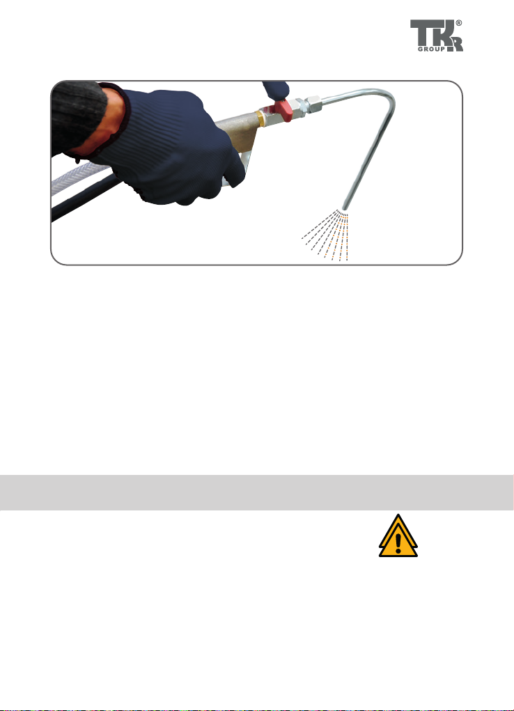
2.4.1
10
2.4 Safety measures at the installation site
The surface on which the device is installed must be level, load-
bearing and stable in accordance with the weight of the device.
The device may only be used in combination with the suction
adapters that are provided for the respective motor type and
an adequately dimensioned vacuum cleaner.
Hoses and supply lines must be routed so that they do not
damage the device and cannot become trapped! The hoses
must also be routed in such a away that they cannot be trip-
ped over.
Fig. 2.4.1
3 .1.1
11
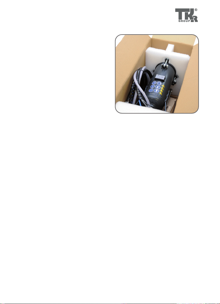
3.1 Unpacking the device
• Place box on a level surface
• Open box and carefully remove the
device
• Check the accessories
- Operating instructions
- Granule container with connected
hose package and handle
- Straight blasting lance
- Angled blasting lance
- Possibly other accessories,
see delivery note
Granule blasting material container with 3-way ball valve, gra-
nule control valve, compressed air control valve, pressure gau-
ge and safety valve.
Hose package with granule transportation hose, and three
colour-coded control hoses.
Handle with 2-way ball valve and connection for the blasting
lance. The control function in the handle is activated using
two control valves connected in series. The operating lever
is equipped with a safety device to prevent unintentional reacti-
vation.
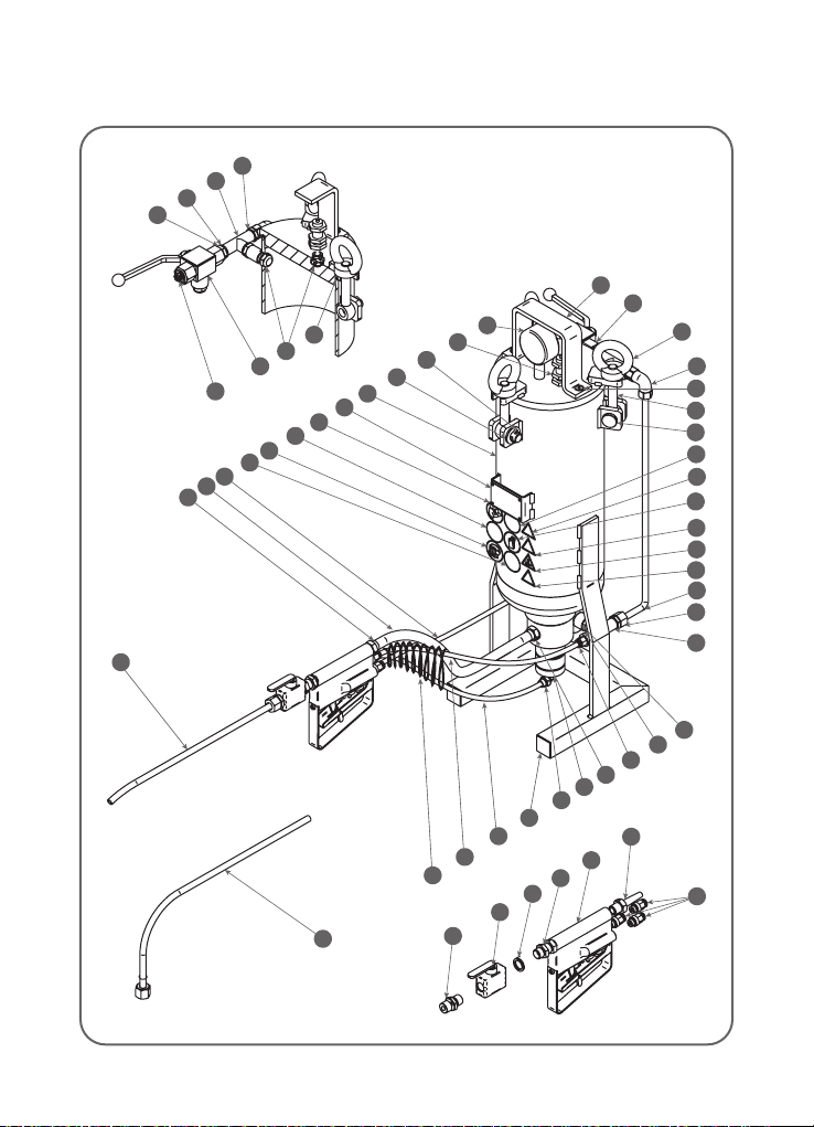
3.2 Identification and description of
the device components
Main elements
of the granule
jet blasting
device
32
38
31
34
21
20
9
22
24
49
18
25
37
27
7
28
7
12
42
46
43
47
45
48
15
26
19
3
1
13
2
17
6
33
44
41
40
39
51
50
30
5
35
10
11
49
18
14
15
36
16
4
17
23
29
8
3.3.1
12
3.3 Device components

13
No. Title
1 Eye bolt
2 Annular nut
3 Pin
4 O-ring
5 Split pin
6 Handle
7Control block
8 PVC hose Ø 14 mm
9 Handle
10 Relief valve
11 Pressure gauge Ø 50 mm
12 Kapsto plastic cover
13 Countersunk screw
14 Double nipple
15 T-piece
16 Exhaust valve
17 3-way ball valve
18 Straight threaded male
connector
19 Ermeto pipe 8x1
20 Bulkhead nipple
21 2-way ball valve
22 Threaded nozzle
23 Nozzle, straight
24 Straight insert nuts
25 Elbow fitting
26 Screw-in fitting
27 Straight male connector
28 Double nipple
No. Title
29 Elbow fitting connection
30 Disc
31 Hose, black Ø 6 mm
32 Hose, blue Ø 6 mm
33 Hose, transparent Ø 6 mm
34 Nozzle, bent
35 Granule container
36 Kapsto sealing screw
37 Press nipple
38 Protective hose
39 Follow manual
40 Observe the general information
41 Wear face mask
42 Wear ear protection
43 Wear gloves
44 Wear protective clothing
45 Warning! System under
pressure
46 Warning! General source of
danger
47 Warning against damage to
hearing
48 Warning against high levels of
noise
49 PVC washer for 1/4“
connection
50 Hose clamp
51 Type plate

290
620
2
3
1
3.4.1
14
3.4 Technical Data
Length 290 mm
Width ca. 280 mm
Height 620 mm
Max. operating pressure 8 bar
Container volume 5 l
Weight 15.5 kg
Hose package working length 4 m
Length and weight without hoses
1 = Control air, transparent hose
2 = Main air, black hose
3 = Granules supply, blue hose
Blasting lance, 3/3-way
straight control valve
Blasting lance,
bent

15
4.1 Operation of the granule jet
blasting device
• Fill with blasting material.
• Connect vacuum adapter to vacuum device.
• Attach blasting lance to handle.
• Connect granule jet blasting device to the
compressed air supply.
• Start the cleaning process.
• Blasting with air / blowing out.
• Blasting with air/granule mixture / cleaning.
• Cleaning the inlet valves and the inlet channel.
• Taking device out of service.
• Maintaining the granule jet blasting device.
Always check the condition of the hoses before starting
up the device!
Stop using defective hoses immediately. Risk of injury!
4.2.1 4.2.2
4.2.4
G1/4“
4.2.3
G1/4“ R1/4“
Ø 6 mm
16
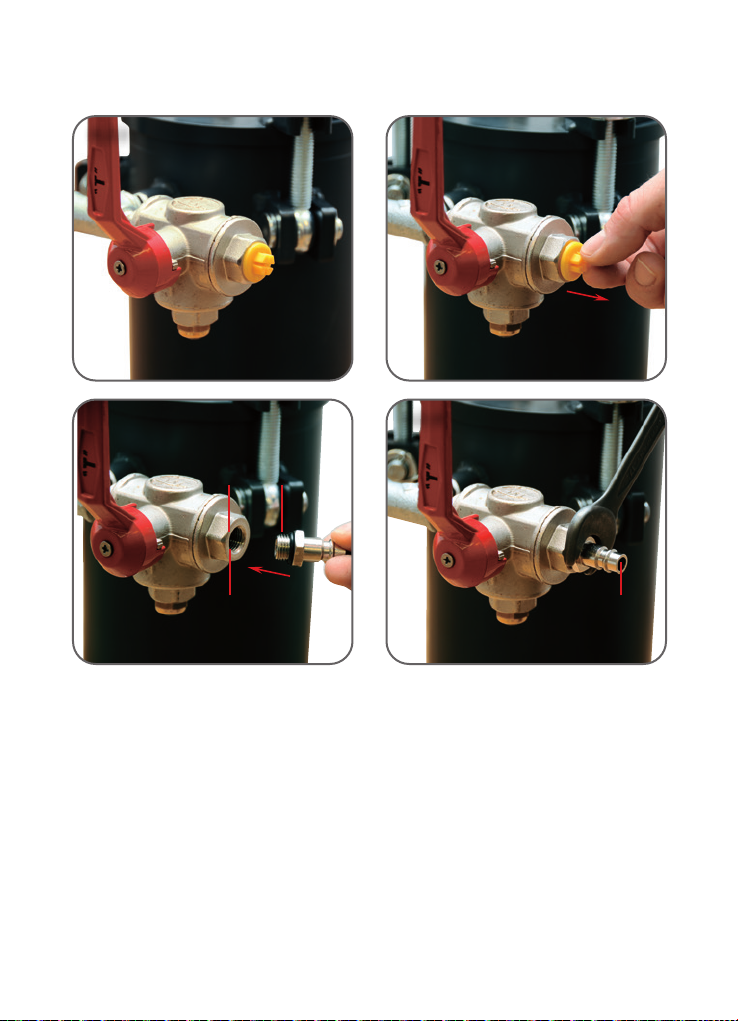
4.2 Granule jet blasting device preparation
and connection
The device is supplied from the factory without a compressed
air coupling. The ball valve has a connecting thread with a
female thread of G ¼“. The thread is fitted with a closing cap.
Insert a suitable compressed air connection with seal into the
thread.
Remove the closing cap.
Tighten the compressed air connection using a suitable tool.
Fig. 4.2.1
Fig. 4.2.2
Fig. 4.2.3
Fig. 4.2.4
4.2.5 4.2.6
≥ Ø 6 mm
4.2.84.2.7
17
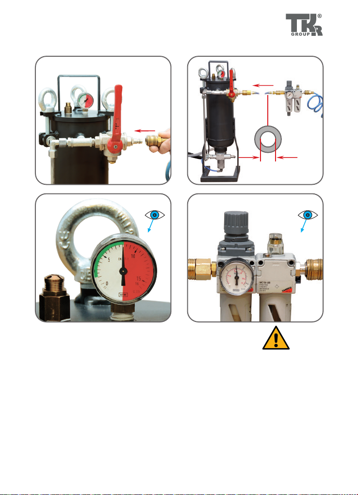
The device may only be operated using dry, oil-free
compressed air!
The granule jet blasting device may only be operated
with an external supply unit with variable operating
pressure!
The operating pressure of the device should be bet-
ween 6 and 8 bar, and may never exceed an operating
pressure of 8 bar!
Fig. 4.2.6
Fig. 4.2.7
Fig. 4.2.8
6–8 barmax. 8 bar

4.3.24.3.1
4.3.3
18
4.3 Filling with blasting material
Fig. 4.3.1
3-way ball valve in „Relieve“ position
Fig. 4.3.2
Pressure gauge must not be indicating
any pressure
Fig. 4.3.3
Undo eye bolts and swivel out swivel-
ling screw fitting
Attention! Device may only be filled if container is de-
pressurised and the air supply line has been discon-
nected.

4.3.6
4.3.4 4.3.5
20–30 mm
19
Only blasting material that has been approved by the
manufacturer may be used: Cleaning granulate.
The blasting material must be free of impurities.
Never re-use blasting material.
Fig. 4.3.4
Remove lid of container
Fig. 4.3.5
Filling with granules
Fig. 4.3.6
Max. filling level 20–30 mm below air
inlet connection

4.3.8
4.3.7
20
4.3 Filling with blasting material
Check device for leaks!
If compressed air is leaking from the device, the working
process must be interrupted and the cause thereof
remedied!
Check lid seal. Seal must be clean and must not be damaged.
Place lid on container.
Fit swivelling screw fitting.
Tighten eye bolts by hand.
3-way ball valve in „Relieve“ position
Fig. 4.3.7
Fig. 4.3.8
Fig. 4.3.9
Fig. 4.3.10
Fig. 4.3.11
Table of contents


