TOPP T240 User manual
INSTRUCTIONS FOR INSTALLATION AND USE
T120
T240
AUTOMATION AND ELECTROMECHANICAL
DRIVERS FOR LINEAR SLIDING DOORS
WITH ONE OR TWO PANELS
COD. 0P5801
EN
VER 1.0
REV 03.18
installer's manual/original instructions


IT
INDEX
EN
INSTRUCTIONS FOR INSTALLATION AND USE
EN
T120-T240
3
1- GENERAL INFORMATION
1.1- General recommendations .......................................................................................pag. 04
1.2- General safety rules ................................................................................................pag. 04
1.3- Installer......................................................................................................................pag. 05
1.4- User...........................................................................................................................pag. 05
1.5- Servicing....................................................................................................................pag. 05
2- TECHNICAL DESCRIPTION
2.1- Rating place and “CE” marking .......................................................................................pag. 06
2.2- Proper use ...................................................................................................................pag. 06
2.3- Technical data .................................................................................................................pag. 06
2.4- Packing ............................................................................................................................... pag. 07
2.5- Models..............................................................................................................................pag. 07
2.6- Preliminary checklist .................................................................................................pag. 10
2.7- Description of parts and dimensions ........................................................................pag. 11
3- INSTALLATION
3.1- General recommendations ......................................................................................pag. 13
3.2- Installing the crossbar ...................................................................................... pag. 13
3.3- Carriage assembly ...................................................................................................pag. 17
3.4- Fastening and adjustment of the sliding panels ........................................................pag. 19
3.5- Installation of Electronic unit, Motor, Transmission belt and Belt........................................pag. 20
3.6- Electric-lock with manual realease ..........................................................................pag. 26
3.7- Installation of enclosed casing.....................................................................................pag. 26
4- ELECTRICAL CONNECTION
4.1- General recommendations................................................................................................pag. 28
4.2- Electrical connection ............................................................................................................pag. 28
4.3- Electronic circuit board......................................................................................................pag. 29
4.4- Electrical wiring diagram (flow chart) ...........................................................................pag. 30
4.5- Connection of detection sensors ...................................................................................pag. 31
4.6- Program selection with MS1 knob..............................................................................pag. 46
4.7- DS2 digital connection ................................................................................................pag. 46
4.8- Devices connection .............................................................................................pag. 47
4.9- Antipanic connection ....................................................................................................pag. 47
4.10- Connetion of Electric-lock ................................................................................................pag. 48
5- USE AND OPERATION
5.1- Technical description ...................................................................................................pag. 49
5.2- Emergency battery ........................................................................................................pag. 49
5.3- First card start-up .......................................................................................................pag. 49
5.4- Reset phase: learning ..................................................................................................pag. 50
5.5- Restart in case of power failure:zero (near).................................................................pag. 50
5.6- Programming parameters .............................................................................................pag. 51
5.7- List of errors and warning ........................................................................................pag. 52
5.8- Self restore management of errors C-D-E-K-N-P-Q .................................................pag. 53
5.9- Self restore management of errors F-G-H-I-J .........................................................pag. 54
5.10- Self restore management after anti panic alarm ...................................................pag. 54
5.11- Self restore management after opening fire or an opening of emergency..........pag. 54
5.12- Digital switch .............................................................................................................pag. 55
6- MAINTENANCE, SPARE PARTS AND DEMOLTION
6.1- Maintenance...................................................................................................................pag. 56
6.2- Spare parts and optional accessories .......................................................................pag. 56
6.3- Demolition ....................................................................................................................pag. 57
7- TROUBLESHOOTING
7.1- Troubleshooting...................................................................................................pag. 57
8- EC DECLARATION OF INCORPORATION OF PARTLY COMPLETED MACHINERY
EU DECLARATION OF CONFORMITY
............................................................................................................pag. 58
IT
GENERAL INFORMATION
1
Before installing the automation the installer must read and understand all parts of this manual.
This manual is an integral part of the automation unit and must be kept by the installer, with all the
enclosed documentation, for future reference..
This manual provides all instructions necessary to ensure correct installation and maintenance of
the automation: TOPP srl is not liable for any damage to persons, animals and property caused by
failure to follow these instructions.
This manual was written by TOPP srl, which holds the copyright. No part of this manual may be reproduced or
published without the manufacturer's written authorization. TOPP srl reserves the right to amend or improve the
manual and the products described therein at any time without notice. The data contained in this manual were
written and checked with the maximum care; TOPP srl is not liable for possible errors due to omissions or printing
errors, or errors in transcription.
1.1
GENERAL RECOMMENDATIONS
1.2
GENERAL SAFETY RULES
The personnel must be informed of the risks of accident, about the safety devices for the operators
and about the general rules for accident prevention foreseen by the international directives and
laws in force in the country in which the automation is installed. In any case, the personnel must
comply scrupulously with the safety regulations for prevention of accidents in force in the country
in which the automation is installed.
During handling and installation of the parts, the personnel shall be equipped with suitable
personal protection equipment (PPE) so as to perform the works required under safe conditions.
To prevent injury and risks for the health of the workers, the maximum limits shall be applied for
manual handling of loads, as provided in standard ISO 11228-1.
Any tampering with or unauthorized replacement of parts or components of the automation
mechanisms and any use of accessories or consumables other than the originals may represent a
hazard and relieves the manufacturer of any civil and penal liability.
In order for the automation unit to operate correctly, shall be carried out periodical maintenance on
it, as indicated in par. 6.1 of this manual. Routine and extraordinary maintenance operations that
require the automation unit to be even partially disassembled should be carried out exclusively
after the power supply to the same has been cut off.
Do not remove or alter the plates and labels applied by the manufacturer on the automation and its
accessories.
Never try to oppose the movement of the door and work near the hinges or other mechanical
moving parts in motion (such as belts, carriages, etc.). The manufacturer is not liable for any
damages caused by improper or unreasonable use of the automation.
When handling electric parts always wear grounded antistatic conductive bracelets as
electrostatic charges can damage the electronic parts on the circuits.
The automation contains mobile mechanical parts, electrical connections and electronic circuits
for control of door movement; the automation must therefore be protected, along its entire length,
by an aluminum casing.
This device may be used by children no younger than 8 years of age, by people with reduced
physical, sensory or mental capacities and by inexperienced users, as long as they are supervised
or as long as they have received instructions on the safe use of the device.
Children must not play with the device.
INSTRUCTIONS FOR INSTALLATION AND USE
EN
T120-T240
4

Contact the installation technician or retailer for assistance.
1.5
SERVICING
1.4
USER
The user must be able to operate the automation under normal conditions and perform simple operations or
startup or resetting the automation following any forced interruptions, using the devices provided (digital switch,
analogue switch, etc.).
The user must not open the casing or perform any operations restricted to maintenance personnel or specialized
experts.
In case of breakdown or malfunction of the door, the user should simply switch off the circuit breaker and abstain
from any attempt to repair the system.
Use of the automation must be exclusively permitted to users who comply with the instructions in this manual and
in the manuals of the TOPP devices connected to it.
Installation of the automation must be done exclusively by qualified technical personnel in
possession of the professional requisites foreseen by the laws in the country of installation.
The installer must verify compliance with the current directives and regulations on the safe use of
motorized doors.
The installer must be able to install the automation, start it and operate it with the power on in
electrical cabinets or shunt boxes, and must be qualified to perform all actions of an electrical and
mechanical nature and any kind of adjustment.
After installing the automation, the installer must analyze the risks to identify any hazardous zones
and ensure that the sliding door system does not present points of crushing, drawing in and/or
shearing, adopting adequate corrective measures where necessary and applying the warning
signs contemplated by the legislation in force.
Every installation shall display the identification of the automation system identifying data in a
clearly visible place.
The installer must also supply the owner with all information regarding automatic, manual and
emergency function of the automation.
The installation technician shall accept full responsibility for any installation errors and for any
failure to adhere to the instructions provided in this manual. The installation technician shall
therefore be exclusively liable for any damages caused to users and/or third parties that may arise
as a result of incorrect installation.
1.3
INSTALLER
INSTRUCTIONS FOR INSTALLATION AND USE
EN
T120-T240
5

2.3
TECHNICAL DATA
Tab. 1 lists the technical data that characterize the T120-T240 automation.
Tab. 1
POWER SUPPLY
PROTECTION OF ELECTRIC DEVICES
WORKING TEMPERATURE
NUMBER OF DOOR PANELS
230V ~ 50Hz
24V 500mA max
0,32A
70W
Continuous
Adjustable 10 ÷ 80 cm/s
Adjustable 1 ÷ 5 cm/s
Adjustable 0 ÷ 60 s
IP X0
2 PANELS
T120
MODEL
PERIPHERAL POWER OUTPUT
POWER ABSORBED
ABSORPTION
OPENING/CLOSING SPEED
OPENING/CLOSING APPROACH SPEED
AUTOMATIC CLOSING TIME
TYPE OF USE
MAINS VOLTAGE FUSE 230V
OPENING/CLOSING ACCELERATION Adjustable 1 ÷ 12
5 x 20 - T800 delayed
MAXIMUM CAPACITY
SIZE OF OPENING
60 + 60 kg
1000÷2800 mm
1 PANEL
120 kg
800÷2800 mm
-20°C
+50°C
0,41A
90W
2 PANELS
T240
120 + 120 kg
1000÷3200 mm
1 PANEL
120 kg
800÷3200 mm
2.2
PROPER USE
The T120-T240 automation mechanism was designed and produced exclusively to operate (open and close)
linear sliding doors in residential, public and industrial buildings.
The door may be used in escape routes only if equipped with anti-panic break-through systems. It must be
possible to break through in the direction of escape no matter what the position of the door.
It is strictly forbidden to use the automation for purposes other than those described herein, in order to guarantee
at all times the safety of the installer and user and the correct function of the automation.
The automation software is designed to perform automatic recovery in the instance where anomalous events as
described in chapters 5.8-5.11.
The automation in order to perform the above, if set in a mode other than "Closed", perform a reset called "Near"
that provides for the complete opening and closing of the doors at a low speed, before returning in the set state the
function selector.
The recovery action must be taken into account in applications where there are features that
provide access control with inputs different from those of the radar for which automation could not
ensure the operating mode set.
In case you want to exclude the auto recovery please contact support Topp Srl.
IT
TECHNICAL DESCRIPTION
2
2.1
RATING PLATE AND “CE” MARKING
The “CE” marking certifies the conformity of the machine to the essential health and safety requisites foreseen by
the European product directives.
It is formed of an adhesive plate made from polyester, screen-printed black, with the following dimensions:
W=50mm - H=36mm.
It should be applied by the installation technician in a clearly visible position on the outside of the automation unit.
INSTRUCTIONS FOR INSTALLATION AND USE
EN
T120-T240
6
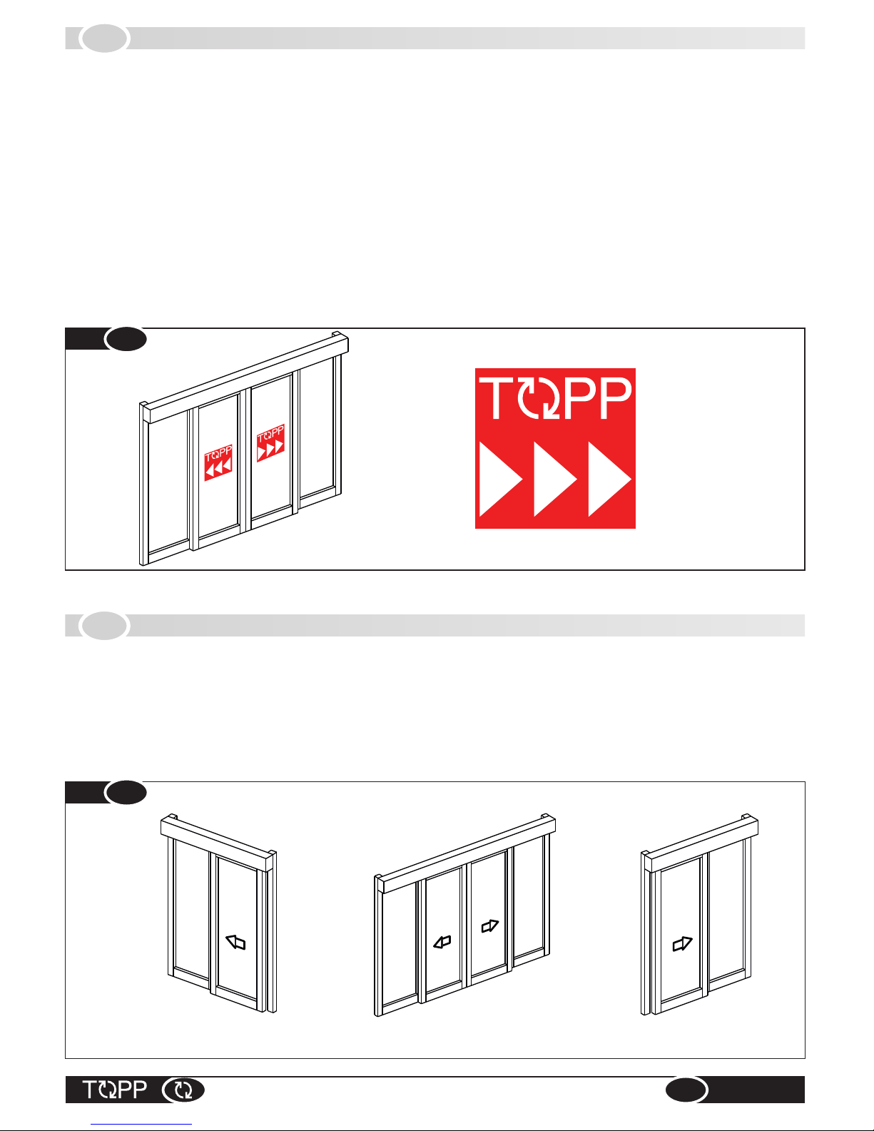
Fig. 2
2.4
PACKING
Every standard product package contains:
%N° 1 panel crossbar,
%N° 1 casing
%N° 1 electronics module with emergency battery,
%N° 1 side cap
%N° 1 motor unit and belt
%N° 1 o 2 Carriage units depending on the number of doors to be automated
%N° 1 Profile of union of Carriage units
%N° 1 belt
%N° 2 door stop limit switch,
%N° 2 warning labels for moving wings that have to be sticked on the centre of the moving wings (Fig.1)
Make sure the parts described above are in the package and that the automation has not undergone any damage
in shipment. If you find anything unusual, do not install the automation and request the service department of the
local retailer or the manufacturer.
2.5
MODELS
Two automation models are available (Fig.2) :
%automation with 2 door panels (Fig.2) which allows a pair of door panels to glide simultaneously in opposite
directions;
% automation with 1 door panels (Fig.2) which allows a single door panel to glide in one direction opens toward
the right or toward the left (taking as reference the front view of the automation);
1 RIGHT DOOR PANEL
1 LEFT DOOR PANEL 2 DOOR PANELS
INSTRUCTIONS FOR INSTALLATION AND USE
EN
T120-T240
7
Warning labels
for moving wings
Fig. 1
INSTRUCTIONS FOR INSTALLATION AND USE
EN
T120-T240
8
Fig. 3
25
VPA
25
S1 S1
VL
LALA
SA SA
VL
LTR
LT
A
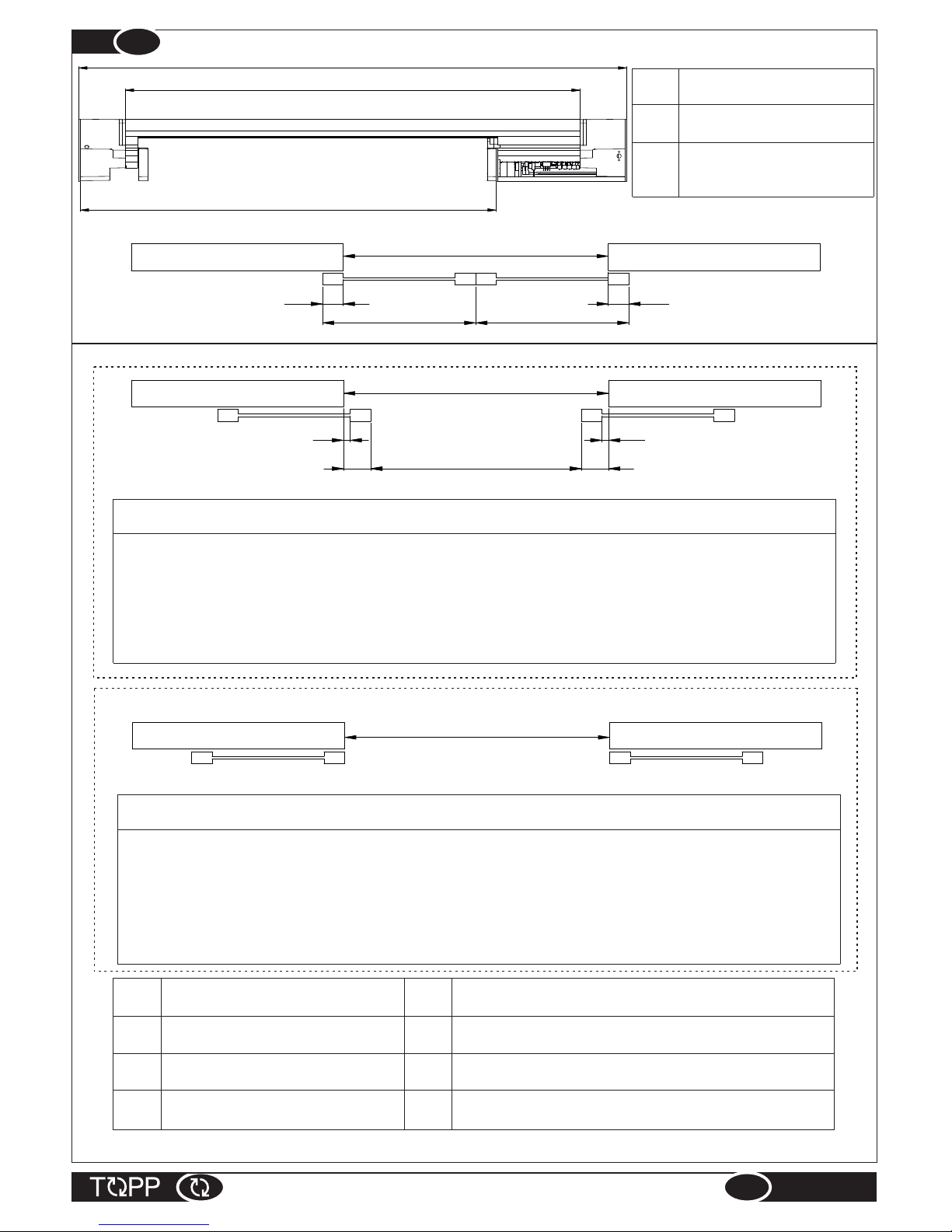
2 DOOR PANELS
Formulas to calculate “VPA”,“LT”,“LTR”, “LA” and “A”
2 panels: VPA = VL - (S1x2) ..................Net doorway width
LT = LTR + 226 .......................Automation lenght
for VPA >1200 LTR = (VPA + S1+ SA) x 2 ....Crossbar lenght
for VPA <1200 LTR = (VPA + S1+ SA) x 2 +200
LA = (VPA/2) + SA + S1 .........Panel widht
A = LTR - 95 ...........................Casing lenght
Formulas to calculate “VPA”,“LT”,“LTR”, “LA” and “A”
2 panels: with S1=0: VPA = VL ............................ Net doorway width
LT = LTR + 226.................... Automation lenght
for VPA >1200 LTR = (VPA + SA) x 2 ....... Crossbar lenght
for VPA <1200 LTR = (VPA + SA) x 2 +200
LA = (VPA/2) + SA ............... Panel widht
A = LTR - 95 ......................... Casing lenght
VPA=VL
S1=0
(1)=safety margin for protection against shearing/drawing in – see standard UNI EN 16005 Par. 4.6.2.1 and Par. 4.6.2.2
VL
Gross opening
SA
Door header with respect to fixed part (wall)
VPA
Net doorway width
A
Casing lenght
LA
Panel widht
LT
Automation lenght
S1
Safety margin (1)
LTR
Crossbar lenght
LT
Automation lenght
LTR
Crossbar lenght
A
Casing lenght

INSTRUCTIONS FOR INSTALLATION AND USE
EN
T120-T240
9
VL
Gross opening
SA
Door header with respect to fixed part (wall)
VPA
Net doorway width
SC
Header of closing door (single wing installation)
with respect to fixed part (wall)
LA
Panel widht
LT
Automation lenght
S1
Safety margin (1)
LTR
Crossbar lenght
A
Casing lenght
LTR
LT
A
Fig. 4
1 DOOR PANEL
VL
SC
LA
SA
VPA=VL
VL
VPA S1
25
Formulas to calculate “VPA”, “LT” , “LTR”, “LA” and “A”
1 Panel:
VPA = VL - S1 ......................................Net doorway width
LT = LTR + 226 ....................................Automation lenght
LTR = (VPA x 2) + (SCx2) + SA + S1...Crossbar lenght
LA = VPA + SA + SC + S1 ..................Panel widht
A = LTR - 95 ........................................ Casing lenght
Formulas to calculate “VPA”, “LT” , “LTR”, “LA” and “A”
1 Panel: with S1=0:
VPA = VL ..............................................Net doorway width
LT = LTR + 226......................................Automation lenght
LTR = (VPA x 2) + (SCx2) + SA ...........Crossbar lenght
LA = VPA + SA + SC ............................ Panel widht
A = LTR - 95 .........................................Casing lenght
S1=0
LT
Automation lenght
LTR
Crossbar lenght
A
Casing lenght
(1)=safety margin for protection against shearing/drawing in – see standard UNI EN 16005 Par. 4.6.2.1 and Par. 4.6.2.2

2.6
PRELIMINARY CHECKLIST
Make sure preparation has been made for the following: power cables for the automation, with passage of the wire
through the wall at the center of the opening "VL" for the external sensor and raceway for the program selector
wire. If no provision has been made these must be provided and, if present, make sure they are located inside the
automation in the free area provided. The free area inside the automation where it is possible to enter with the
wires is shown in Fig. 5-6.
We recommend providing in zone A for convergence of the various wires into a shunt box with a cover, installed
flush to the wall, so that it will be possible to make the various derivations in the box and drill the holes for the wires
directly on the lid.
INSTRUCTIONS FOR INSTALLATION AND USE
EN
T120-T240
10
A
A
A
Fig. 6
Fig. 5
90
22
14
14
22
90LTR
LTR
VL
LTR
37
CT
H
A-B
H
H .... Fastening height automation
CT ...Center of the beam
Free area for cable entry Free area for cable entry
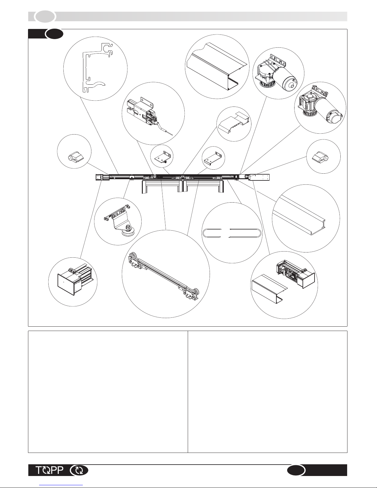
2.7
DESCRIPTION OF PARTS AND DIMENSIONS
INSTRUCTIONS FOR INSTALLATION AND USE
EN
T120-T240
11
1 -
2 -
3 -
4 -
5 -
6 -
8 -
Carriage
Transmission Belt Unit
Door stop
Main crossbar (header beam)
Long door panel drive bracket
12 - Wire raceway
13 -
14 - Toothed belt
9 -
10 -
11a -
Door lock with manual release
Casing
Gearmotor and encoder T120
Lateral case fastener
Electronic control circuit, low voltage
5
1
313
10
78
14
2
4
6
4
9
12
Fig. 7
7 - Short door panel drive bracket
Casing bracket
transformer and Emergency battery
11b -Gearmotor and encoder T240
11a
11b
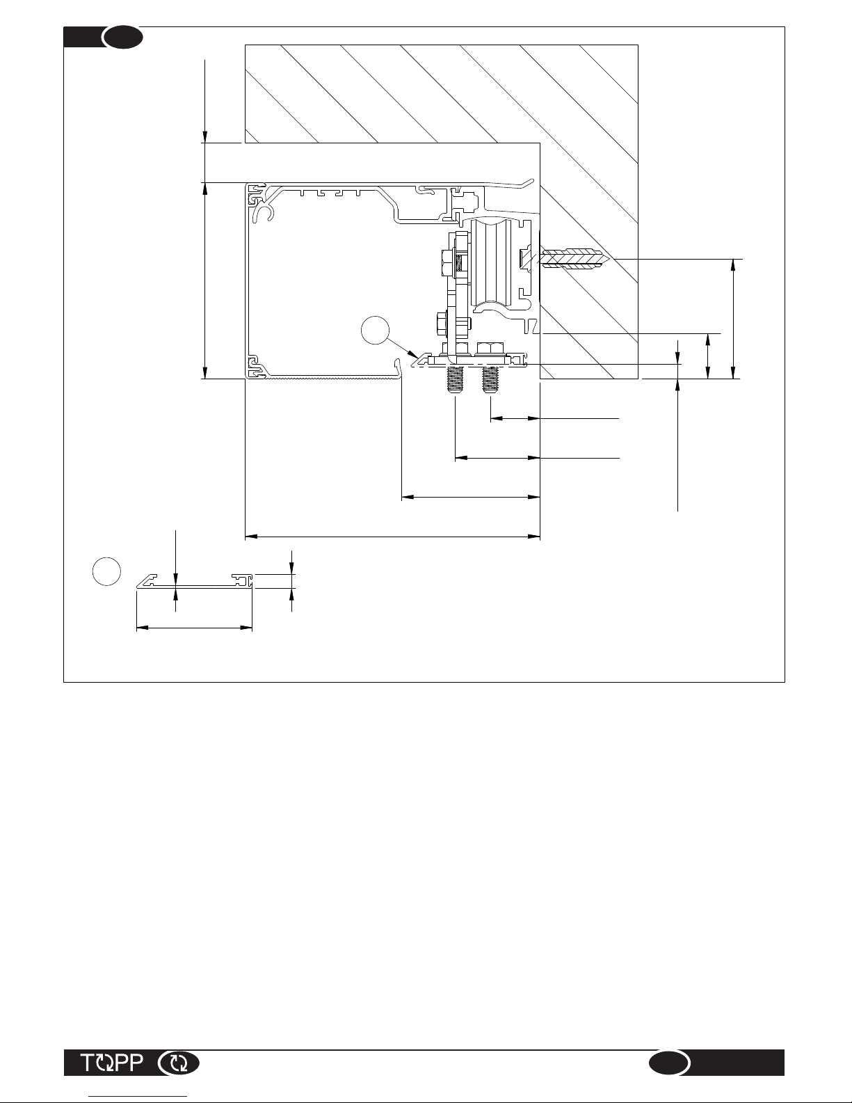
Fig. 8
20 MIN100
150
70
25 MIN
43 MAX
23
7.5 +/-7.5
7
1.5
59
CARRIAGE COVER
OPTIONAL COD. 1P6905
A
61
INSTRUCTIONS FOR INSTALLATION AND USE
EN
T120-T240
12
A

3.2
MONTAGGIO DELLA TRAVERSA
Open the package and remove the beam. Inspect it to make sure it has not undergone any damage in shipment.
Mark the measurement on the beam where it has to be cut; this measurement is calculated according to the
formulas detailed in Section 2.5.
After cutting the beam to the proper size and eliminating any burrs, mark it halfway along its length, at the center
point. Starting from the center, drill holes measuring 6.5 mm, or the proper diameter for the screws you intend to
use to fasten it to the wall, spacing them 300 mm apart until you reach the two ends. If the last hole should be more
than 100mm from the end, drill another fastening hole at 100 mm.
A drilling reference is present along the entire length as shown in Fig. 9.
After drilling the necessary holes, clean the beam thoroughly to remove any residues.
Important: before installing the beam make sure the holes and raceways necessary for the passage
of the power wires and control and/or safety accessories are present and correctly positioned,
otherwise prepare them first where needed, as shown in Fig. 5-6.
3.2
INSTALLING THE CROSSBAR (HEADER BEAM)
Fig. 9
LTR
300 300
6.5
100 100
= =
IT
INSTALLATION
3
3.1
AVVERTENZE GENERALI
The automation must be installed exclusively by competent, qualified technical personnel in
possession of the technical requisites foreseen by the legislation in force in the country of
installation.
Do not install the automation on the external wall of the building, subject to atmospheric agents
(rain, snow, etc.).
Do not use the automation in environments with a potentially explosive atmosphere.
The glass for door panels shall comply with the provisions of the Standard (EN 16005 4.4.2 -
Materials: tempered glass in accordance with EN 12150_1; stratified glass in accordance with EN
ISO 12543-1 and EN ISO 12543-2).
During installation of the door, take care to avoid any risks during the movement of closure and/or
opening the door, and to protect against risks in accordance with the provisions of standard EN
16005 at item 4.6.21 for the door opening movement and item 4.6.2.2 for door closure. Protection of
the primary closing edge should take account of the types of users of the door (see EN 16005,
4.6.2.2).
The forces developed by the complete system during operation must respect the regulations in
force in the country of installation; if this is not possible, protect and signal by means of electronic
safety devices the zones affected by those forces.
Before installing the automation, verify that the structure to be automated is stable, sturdy and
able to withstand the weight of the automation and, if necessary, take steps to ensure that it is.
Topp Srl is not liable for failure to comply with the rules of good workmanship in the construction
of the door panels to motorize, or for any distortions that may develop with use of the device.
3.1
GENERAL RECOMMENDATIONS
INSTRUCTIONS FOR INSTALLATION AND USE
EN
T120-T240
13

(2-wing model)
To install the beam, proceed as follows:
Mark the center of the door opening VL on the surface to
which the automation will be fastened. This will match
the center of the beam CT Fig. 10.
Take as your reference the measurements listed in Fig.
8 and calculate the position H in height at which you
want to fasten the automation and mark on the CT line
previously drawn the point at which you will make the
first hole to fasten the beam (Fig. 10). This
measurement may depend both on the type of wing you
plan to install and on the esthetic effect your wish to
obtain with the wings open or closed. If you already
have the wings that will be installed, calculate the height
taking account of the total height of the wing, including
any adapters for fastening to the carriage, plus about
7mm gap between the floor and the wing.
Important: the maximum adjustment in height of
the wings is 7.5mm upward or downward, with
respect to the height of fastening to the carriage
indicated in Fig.8.
If the floor is not perfectly flat, decide the position of
fastening in height H, taking as reference the highest
point of the floor in the zone on which the wings will
glide.
Fasten the beam to the wall starting from the central
hole on the beam Fig. 11.
Important: to fasten the beam, first determine what
type of screws and/or anchors to use, depending on
the type of wall support, in order to guarantee solid,
safe, workmanlike fastening. If it should be necessary
to use anchor bolts or other fastening system that
require drilling the wall, proceed as follows: drill the first
central hole, clean the hole and the area around it
before positioning the beam, fasten the beam to the wall
using the proper size screw and/or anchor fitted in the
hole you have just drilled.
Important: check that the wall does not have any
uneven spots along the entire length of the
automa ti on and provid e to el im in ate any
protrusions and/or fill any dents to even the
surface.
Now mark the other holes with a pencil (Fig.12) taking
care to maintain the beam perfectly horizontal and/or
parallel to the floor. After marking the holes, detach the
beam and drill the other holes in the wall, blow and clean
everything thoroughly and fasten the beam, always
starting from the central hole and moving from it to the
ends, checking constantly to be sure the beam remains
perfectly horizontal and/or parallel to the floor.
D
Fig. 10
Fig. 12
Fig. 12
VL
= =
H
CT
H
CT
Fig.
Fig. 11
INSTRUCTIONS FOR INSTALLATION AND USE
EN
T120-T240
14
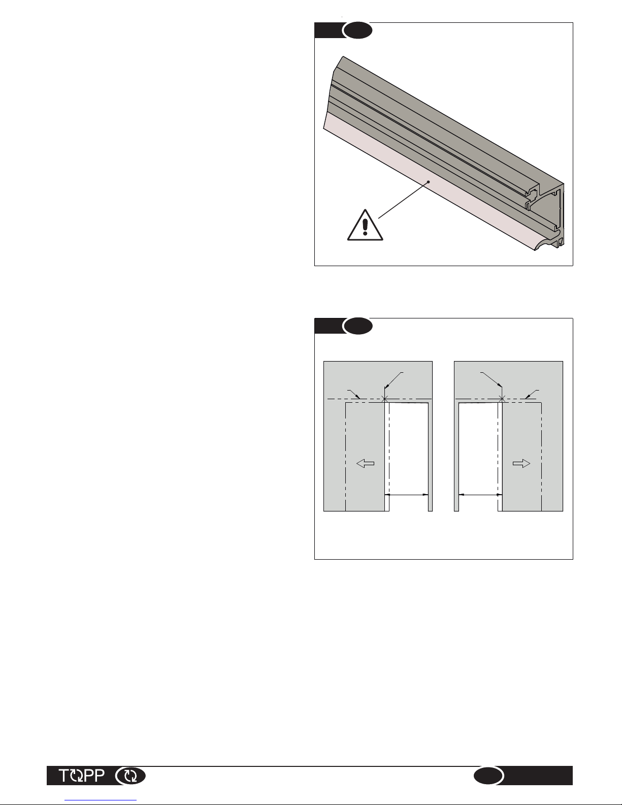
(1-wing model)
To install the beam, proceed as follows:
Mark the center of the beam CT on the surface to which
the automation will be fastened. This will be:
- on the left side of the opening space for applications
with one wing opening toward the left (Fig.14);
- on the right side of the opening space for applications
with one wing opening toward the right; (Fig.14);
Take as your reference the measurements listed in Fig.
8 and calculate the position H in height at which you
want to fasten the automation and mark on the CT line
previously drawn the point at which you will make the
first hole to fasten the beam (Fig. 14). This
measurement may depend both on the type of wing you
plan to install and on the esthetic effect you wish to
obtain with the wings open or closed. If you already
have the wings that will be installed, calculate the height
taking account of the total height of the wing, including
any adapters for fastening to the carriage, plus about
7mm gap between the floor and the wing.
Important: the maximum adjustment in height of
the wings is 7.5mm upward or downward, with
respect to the height of fastening to the carriage
indicated in Fig.8.
Important: never, for any reason, drill the holes with
the beam attached.
Important: if you plan to use self-tapping screws
and therefore do not need to drill holes, be very
careful when inserting and fastening the screws not
to damage the carriage glide rail. Use tools that do
not touch the glide surface or else take care to
protect it adequately (Fig. 13).
Important: if the glide rail should be damaged
during installation, it will be necessary to replace
the whole beam.
After fastening the beam to the wall, clean it thoroughly
with nitrogen thinner or denatured alcohol, so as to
eliminate any drilling residue or dirt. Check by running
your hand over the glide rail that it is perfectly smooth
and clean.
Fig. 13
Fig. 14
VL VL
HH
SX DX
CT CT
INSTRUCTIONS FOR INSTALLATION AND USE
EN
T120-T240
15

If the floor is not perfectly flat, decide the position of
fastening in height H, taking as reference the highest
point of the floor in the zone on which the wings will
glide.
Fasten the beam to the wall starting from the central
hole on the beam (Fig. 15).
Important: to fasten the beam, first determine what
type of screws and/or anchors to use, depending on
the type of wall support, in order to guarantee solid,
safe, workmanlike fastening. If it should be necessary
to use anchor bolts or other fastening system that
require drilling the wall, proceed as follows: drill the first
central hole, clean the hole and the area around it
before positioning the beam, fasten the beam to the wall
using the proper size screw and/or anchor fitted in the
hole you have just drilled.
Important: check that the wall does not have any
uneven spots along the entire length of the
automa ti on and p rovide to elim in at e any
protrusions and/or fill any dents to even the
surface.
Now mark the other holes (Fig. 12) with a pencil, taking care to maintain the beam perfectly horizontal and/or
parallel to the floor. After marking the holes, detach the beam and drill the other holes in wall, blow and clean
everything thoroughly and fasten the beam, always starting from the central hole and moving from it to the ends,
checking constantly to be sure the beam remains perfectly horizontal and/or parallel to the floor.
Important: never, for any reason, drill the holes with the beam attached.
Important: if you plan to use self-tapping screws and therefore do not need to drill holes, be very careful
when inserting and fastening the screws not to damage the carriage glide rail. Use tools that do not touch
the glide surface or else take care to protect it adequately (Fig. 13).
Important: if the glide rail should be damaged during installation, it will be necessary to replace the whole
beam.
After fastening the beam to the wall, clean it thoroughly with nitrogen thinner or denatured alcohol, so as to
eliminate any drilling residue or dirt. Check by running your hand over the glide rail that it is perfectly smooth and
clean.
IRON 2 mm (with lesser thickness use threaded rivets)
3 mm (with lesser thickness use threaded rivets)
100 mm
50 mm
Minimum thickness
Materials of the fastening surface
ALUMINUM
SOLID WOOD
REINFORCED CONCRETE
110 mm (with lesser thickness use chemical bolts)
PERFORATED CONCRETE
H
CT
Fig. 15
INSTRUCTIONS FOR INSTALLATION AND USE
EN
T120-T240
16

Cut the profile "PC" to the length resulting from the formula see Fig. 16 . If necessary it is, however, always
possible to shorten the profile "PC".
Important: to guarantee the stability of the wing we recommend that you do not exceed the limit “Y”,
which indicates one-third of the wing width, with the axis of the wheel “X”.
3.3
CARRIAGE ASSEMBLY
INSTRUCTIONS FOR INSTALLATION AND USE
EN
T120-T240
Fig. 16
PC=LA-300
LA
150 150
Y=1/3 LA
PC
X X
Y Y
2 DOOR PANELS
250 200PC=LA-450
LA
Y=1/3 LA Y=1/3 LA
X X
PC
1 DOOR PANEL
17
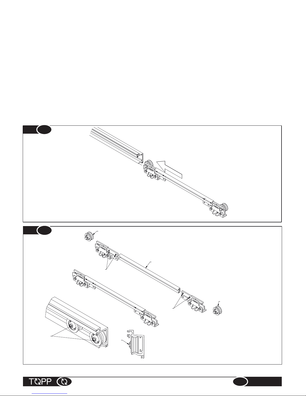
Fit the carriage on the profile "PC" and fasten the dowels "GR".
If there is room enough on at least one side of the beam, it is possible to slide the carriages, assembled in this way,
directly on the beam (Fig.17).
If neither of the two sides of the beam is free, to insert the assembled carriage remove the wheels "RC" (Fig. 18).
Insert the wheels "RC" on the beam previously installed, fitting them from the sides and turned as shown in Fig. 18.
Then fasten the carriages to the wheels and tighten the fastening screws "VC" (Fig.19).
Assembly of the wings on the carriages
Assembly the carriage fastening screws "VA" on the wings and fasten the wings to the carriages, taking care to
center the carriage assemblies on the wing (Fig. 16).
Important: to fasten the carriages to the wings and then be able to adjust them, take care to use hexagonal
screws "VA" of adequate length for the fastening system employed. Fig. 19 shows the fastening system
used for our profiles P45.
Important: at this point it is necessary to install the limit switches "FC" provisionally on the beam to stop
the wings and prevent them from slipping out and creating a hazardous condition (Fig. 19).
INSTRUCTIONS FOR INSTALLATION AND USE
EN
T120-T240
18
Fig. 17
PC
RC
RC
GR
GR
Fig. 18
RC RC

3.4
FASTENING AND ADJUSTMENT OF THE SLIDING PANELS
The adjustments available for each wing are as follows: in height, using the adjustment nuts "DR", and in depth
using the screws "VA" (Fig. 20).
Height adjustment:
Start by adjusting the wing height so as to ensure a space between the bottom of the door and the highest point
on the floor, leaving a clearance of about 5-7mm. The possibility to adjust the height of the carriage wheels
independently for each wing makes it possible to correct the perpendicularity of the wing with respect to the floor
and the parallelism between the two wings. To perform these adjustments, use a no. 10 fixed wrench to loosen
the screws fastening the carriages at the top "VF1", then make the adjustments with the same wrench by turning
nuts "DR".
After setting the height of the wing, fasten the screws "VF1".
Adjustment in depth:
Loosen screws "VA" slightly and adjust the wings parallel and at the desired distance from the wall.
Important: the distance of the wings from the wall is regulated by specific standards in some countries,
so as to reduce the shearing and dragging risks to a minimum. For the European community, refer to the
provisions of standard EN16005.
After making these adjustments, fasten the screws "VA".
Apply the special glide runner to the floor, using the appropriate type of fastener for the door structure installed,
and taking care to ensure that the wing remains parallel to the wall along its entire height.
After completing the adjustments of the wings and fastening the runners, test the movement by sliding the door
manually to make sure it glides freely along the entire length of the automation and does not slip out of the runner
on the floor, either when it is fully open or when it is fully closed. If necessary adjust the limit switches "FC".
Check after fastening all the screws on the carriages.
INSTRUCTIONS FOR INSTALLATION AND USE
EN
T120-T240
Fig. 19
VC
VC
FC
VA
VA
GF
19

INSTRUCTIONS FOR INSTALLATION AND USE
EN
T120-T240
Fig. 20
VA
VA
DR
DR
VA
VF1
DR
Before installing the motor unit, the transmission belt
and the belt on the beam, make sure all the final
adjustments have been made on the carriages and
wings.
Installation of electric unit and motor
Insert the three square nuts supplied on the beam and
position them as shown in Fig. 21. The electric unit will
be fastened to the nut positioned at 180mm, while the
motor unit will be fastened to the other two.
Fig.22- Remove the casing on the electric unit by
unfastening the bottom part first, pulling it manually first
in at the position indicated as no. 1 and then at the sides
no. 2-3, then slide it off no. 4, holding it slightly open with
your hands no.5.
Fasten the electric unit to the beam, first at the top Fig.
23 no. 1 and then lowering it until is snaps into place Fig.
23, no.2. Check that the head of the unit rests on the
beam and then use a 5 mm socket wrench to fasten the
screw "VE" (Fig. 24).
With the same 5 mm socket wrench, fasten the two
screws "VM" of the motor unit on the beam Fig. 25,
positioning it at height "A" listed in Tab. 2.
3.5
INSTALLATION OF ELECTRONIC UNIT, MOTOR, TRANSMISSION BELT AND BELT.
Fig. 21
180
380
450
20
This manual suits for next models
1
Table of contents


