topSenso topCam 6500 User manual

- 1 -
Manual topCam 6500 (Ver. > 3.5.4)
topSenso GmbH
Platanenring 10
D - 61352 Bad Homburg
Germany
Contact:
Tel. +49 6172 944606
Fax +49 6172 944607
E-mail [email protected]
Internet www.topSenso.de

- 2 -
Table of content
Manual topCam 6500 (Ver. > 3.5.4) .....................................................................................1
1. EMV test ....................................................................................................................3
2. Technical specifications..............................................................................................3
2.1. Scanning field:........................................................................................................3
2.2. Inputs/Outputs:........................................................................................................3
2.3. Interfaces: ...............................................................................................................3
topCam6500 connection panel............................................................................................4
2.4. Dimensions.............................................................................................................4
3. Connector pin assignment HD-15 connector ..............................................................4
4. Connector pin assignment Video output (round socket)...............................................5
5. topCam 6500 lenses....................................................................................................5
6. Symbologies: ..............................................................................................................5
6.1. Data matrix code ECC200 scanning:.......................................................................6
6.2. Bar code scanning: horizontal, vertical or omnidirectional.....................................6
6.3. OCR/OCV ..............................................................................................................6
6.4. Gauge pin (contour tracing).....................................................................................6
7. Installation..................................................................................................................7
7.1. Positioning and scanning distance ...........................................................................7
8. Electrical connection...................................................................................................7
8.1. Power supply ..........................................................................................................7
8.2. In and outputs .........................................................................................................7
8.3. Serial interfaces.......................................................................................................8
8.4. TCP/IP connector....................................................................................................8
9. Control monitor ..........................................................................................................9
10. Code sizes of the data matrix code ..........................................................................9
11. Print quality parameters and their classifications ...................................................10
12. Operation..............................................................................................................10
12.1. The topControl user interface l.........................................................................10
Selection window (window function)............................................................................12
Settings of the data matrix code scan ................................................................................12
Settings bar code scanning................................................................................................13
OCR/OCV scanning settings...........................................................................................14
MICRO PDF 417 (stacked bar code).................................................................................18
Function window..............................................................................................................19
Interface settings...............................................................................................................19
Options.............................................................................................................................20
Output format...................................................................................................................21
Format..............................................................................................................................21
Lighting adjustment from 1-99 .............................................................................................22
13. The user interface topControllite...........................................................................23
14. Error status data matrix code:................................................................................26
15. Error status bar code: ............................................................................................26
16. Trouble shooting...................................................................................................27
17. Scanning the data matrix code in envelope windows .............................................28

- 3 -
1. EMV test
2. Technical specifications
2.1.Scanning field:
HD: Image area 21 x 17 mm (high density) scanning distance 55 mm
SD: Image area 32 x 25 mm (default density) scanning distance 80 mm
ED: Image area 40 x 30 mm (expanded scanning area) scanning distance 100 mm
Optional: Various focal length and scanning windows
Scanning distance:55 mm/80 mm +/- 5 mm
Lighting:Internal LED flash red (optionally white)
Optional: external lighting
2.2.Inputs/Outputs:
2 potential-free inputs (trigger,
input 2)
2 potential-free outputs, short-circuit-
proof
(continuous current max. 200 mA)
2.3.Interfaces:
1 RS232 process interface
(2400 - 115200 baud)
1 RS232 controlling interface
115200 baud (optional 9600 baud)
1 Ethernet adaptor TCP/IP 100 MB/sec auto negotiation

- 4 -
topCam6500 connection panel
2.4.Dimensions
Casing: 127 x 68 x 48 mm
3. Connector pin assignment HD-15 connector
HD 15 connector Signal name Description RS-232
connector
with
process
Sub-D 9
RS 232
connector
service
interface
1GND Reference potential
for power supply
2TXD Process interface 2
3RXD Process interface 3
4IN 2 (unused)
5 12-24 volts Power supply
6assigned
7RXD Service interface 3
8assigned
9TXD Service interface 2
10 RS 232 GND Reference potential of
the RS-232 interfaces 5 5
11 IO 12-24 Volt Supply of the
insulated outputs
12 OUT 1 (READ) Output current max.
200 mA
13 OUT 2 (NOREAD) Output current max.
200 mA
- 5 -
14 IN 1Trigger input
15 IO GND Reference potential
for insulated inputs
4. Connector pin assignment video output (round socket)
The plug is screwable (plug in and tighten)
7-pole miniature socket Signal name HD-15 VGA socket
1 H-Sync 13
2 V-SYNC 14
3GND 6
4GND 10
5Blue 3
6Red 1
7Green 2
5. topCam 6500 lenses
Focal length Distance to codeScanning window
8mm 55 mm 36 x 27 mm
80 mm 56 x 42 mm
12 mm 55 mm 21 x 17 mm
80 mm 32 x 25 mm
100 mm 40 x 30 mm
120 mm 60 x 45 mm
9.5 mm 55 mm 24 x 18 mm
80 mm 34 x 25 mm
95 mm 40 x 30 mm
6. Symbologies:
-Data matrix code ECC 200 (max 35 Hz), max 6m/sec), micro PDF 417, EAN data matrix
-Bar code scanning (code I 2of5, Code 39/32, code 128 A,B,C, EAN 8/13, UPC A/E)
Pharma code (max 40 Hz, max 6m/s)
-OCR/OCV scanning (2 windows max 30 objects (Optional: 2 windows with max 30
objects), window, 1 x adjusting window)
-Gauge-pin recognition (object recognition)
-Label position, distance measurement, print image control

- 6 -
-Area measurement
6.1.Data matrix code ECC200 scanning:
-dark code on light background (automatic or configurable)
-light code on dark background
-code sizes from 10 x 10 to 48 x 48 square
-all rectangular codes up to 16 x 48
-aligned, 90 degrees aligned +- 30 degrees, independent from rotation position
-evaluation speeds: < 40 Hz
-movement speeds : 6m/s
- data formats data matrix: ASCII,C40,text, X12, Edifact, Base 256, extended Base 256
-maximum data capacity: 348 numerical, 259 ASCII, 172 Bytes
-printing quality parameters (contrast, grid non-uniformity, error correction)
6.2.Bar code scanning: horizontal, vertical or omnidirectional
- code interleaved 2 of 5
- code 39/32
- code 128 A,B,C
-EAN 8/13
-UPC A/E
- pharma code
- optionally with or without check sum
-length specifications
6.3.OCR/OCV
-character set teachable (max 40 characters)
-mask generator
-product storage up to 25 different products
-scanning, verification or pixel counter
- up to 2 different scanning windows
- up to 30 objects per window
- 1 adjusting window
-scalable objects
-adjustable parameters
-light objects on dark background
-dark objects on light background
-also suitable for inkjet code
-scanning speed approximately 3ms/object + image import17ms
-overlay representation
-guided user interface
6.4.Gauge pin (contour tracing)
-gauge pin teachable as object
-tolerance specifications
-display of coordinates
-light or dark object
- Windowsprogramme for representation and teaching of gauge pin

- 7 -
7. Installation
7.1.Positioning and scanning distance
The topCam6500 is fitted at a distance of 80mm (SD version) from the surface. In case of
reflecting surfaces (e. g. labels) the topCam6500 should be mounted in an inclined position, as
shown in Figure 1, in order to eliminate direct reflections.
55
Figure 1: Scanning distance and incline of the topCam6500
8. Electrical connection
8.1. Power supply
The topCam6500 is supplied with a direct voltage of 18 volts to 24 volts. The supply voltage
is impressed between pin 5 (+10..24 volts) and pin 1 (GND). The topCam6500 is protected
against incorrect polarity of the supply voltage.
8.2. In and outputs
The optically insulated in and outputs of the topCam6500 have their own supply connections.
The outputs receive their supply voltage of 18-24 volts from pin 11 of the HD-15 connector.
The output signals are PNP signals.
Reference position for the inputs is pin 15 of the HD-15 connector.
The outputs are short-circuit proof. They switch off automatically in case of overload. In
order to reactivate the outputs after such an overload turnoff, switch the supply voltage at the
outputs off and on.
Output 1 (pin 12 of the HD-15 connector) is activated when a code has been scanned
correctly.
Output 2 (pin 13 of the HD-15 connector) shows a scanning error. Polarity and duration of
activation of the outputs are configurable.
Input 1 (pin 14 of the HD-15 connector) serves as a trigger input. The polarity of the trigger
signal is configurable.
Input 2 resets the statistical counters if a voltage is applied on the input for approximately 3
seconds.
If the trigger delay is to be realized by means of an incremental encoder the signal of the
incremental encoder is to be applied on input 2.

- 8 -
8.3. Serial interfaces
The topCam6500 has two serial interfaces. A process interface and a diagnosis interface. If
the topCam 6500 is integrated in the machine and the process interface is connected the
scanning can be recorded by means of the diagnosis report during the operation. An in process
control is possible.
In addition, simultaneous output of the data to the process port and the diagnosis port is
possible.
The two serial interfaces of the topCam6500 are galvanically isolated from the residual
device, therefore they have their own point of reference (pin 10 of the HD-15 connector).
The first serial interface (pin 2 und 3 of the HD-15 connector) links the topCam6500 with the
process environment.
The second serial interface (pin 7 and 9 of the HD-15 connector) serves as a link between the
topCam6500 and a PC. This interface works with a fixed data rate of 115200 baud, the data
format is 8 data bits, 1 stop bit, no parity.
8.4. TCP/IP connector The TCP/IP allows direct connection by
means of the IP address. The MAC
address is associated with the serial
number of the device which allows
parallel connection of several topCams
with different IP addresses on one
switch. The MAC address cannot be
changed. The IP address can be changed
by a command.This new IP address
will not be activated until a reset is
made. Note! The settings must be saved.
When the topCam 6500 is switched on
the monitor will show the IP address.
Also the process port can be determined
if output of the scanned data is to be made via the RS232 or the TCP/IP port. The Windows
user interface can be operated via the TCP/IP and the RS232 Port. The following commands
can be entered in the command line of the topControl programme:
Changing of the IP address is possible in the menu item SYSTEM ENTER COMMANDO
which will open a window.
The IP address is set to 192.168.120.102 on delivery and can be changed as follows: Enter:
IN:M:t192.168.120.103 in the command window. With the command IN:Q:n n= 0 process
port the RS232 is, n=1 process port is the TCP/IP port.
All changes must be saved in the Flash and will be activated after switching off and switching
on again.
Important!!!! The port address for TCP/IP is port 23

- 9 -
9. Control monitor
A commercially available VGA monitor can be connected to the 7-pole miniature port. It
displays the image which was recorded last. A compatible link cable is also included in the
delivery of the topCam6500.
Inverse DM code rectangular DM code EAN13 code DM code
This figure shows and image of a VGA monitor with a varying code
10. Code sizes of the data matrix code
Symbol size Data region Data bytes error correction Data capacity max rectifiable
vert horiz. num alpha byte bytes
10 10 8 x 8 3 5 6 3 1 2
12 12 10 x 10 5 7 10 6 3 3
14 14 12 x 12 8 10 16 10 6 5
16 16 14 x 14 12 12 24 16 10 6
18 18 16 x 16 18 14 36 25 16 7
20 20 18 x 18 22 18 44 31 20 9
22 22 20 x 20 30 20 60 43 28 10
24 24 22 x 22 36 24 72 52 34 12
26 26 24 x 24 44 28 88 64 42 14
32 32 28 x 28 62 36 124 91 60 18
36 36 32 x 32 86 42 172 127 84 21
40 40 36 x 36 114 48 228 169 112 24
44 44 40 x 40 144 56 288 214 142 28
48 48 44 x 44 174 68 348 259 172 34
8 18 6 x 16 5 7 10 6 3 3
8 32 6 x 28 10 11 20 13 8 5
12 26 10 x 24 16 14 32 22 14 7
12 36 10 x 32 22 18 44 34 20 9
16 36 14 x 32 32 24 64 46 30 12
16 48 14 x 44 49 28 98 72 47 14
- 10 -
11. Print quality parameters and their classifications
Quality class Contrast error correction Grid non-uniformity Axial non-uniformity
A>=70 >=62 <=38 <=6
B>=55 >=50 <=50 <=8
C>=40 >=37 <=63 <=10
D>=20 >=25 <=75 <=12
F< 20 < 25 > 75 > 12
12. Operation
All parameters relevant for the operation of the topCam6500 can be easily set by means of the
operation programme topCamControl. In addition, this programme allows to store device
settings and to save recorded images.
12.1. The topControluser interface
The topControl user interface allows operation of the topCam6500 via a PC COM port or to
establish a communication via Ethernet for the topCam using an Ethernet adapter.
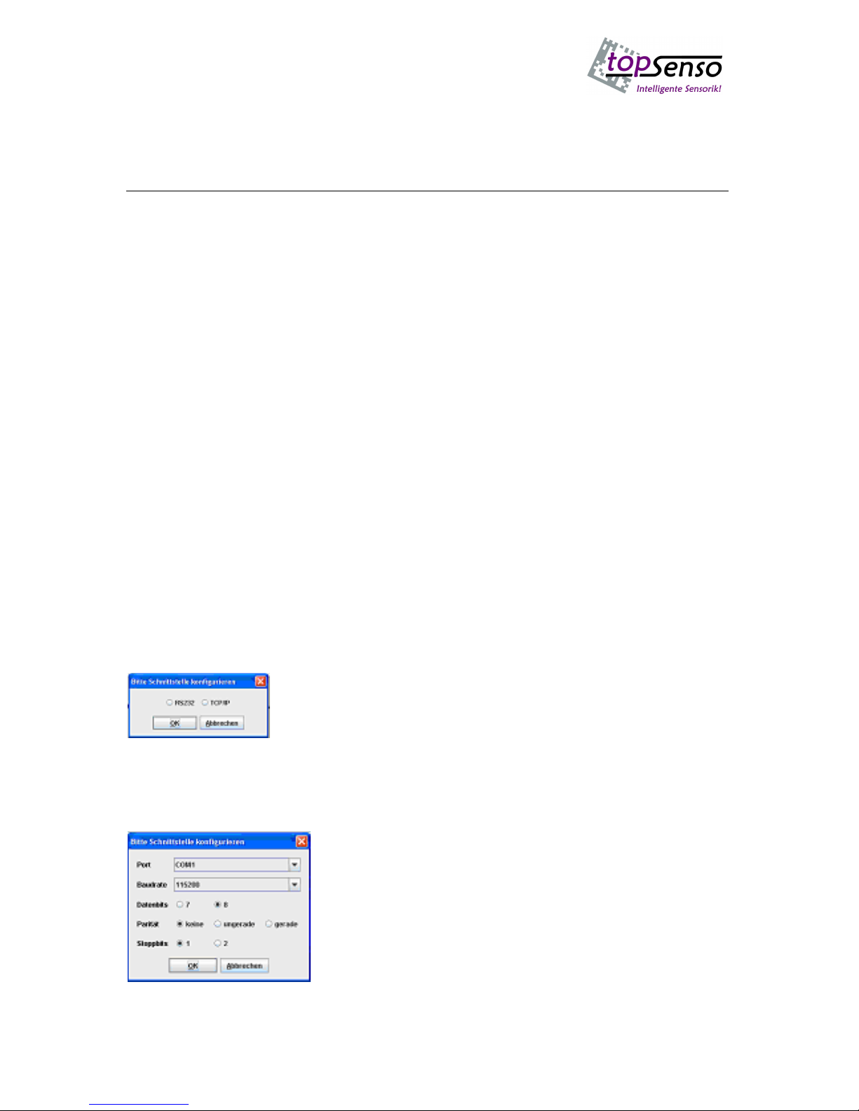
When the programme is started for the first time it will be asked if the topCam is to be
controlled via the RS232 or the TCP/IP Ethernet connection.
Selecting the connection
If the COM port connection is selected the system’s available COM interfaces will be
scanned; if more than one interface is available the programme will scan for the COM port to
which the topCam is connected when being started for the first time.
Connection to RS232 with adjustable parameters

- 11 -
When selecting the TCP the menu will request the IP address.
NOTE! The PORT number mustalways be entered with 23. (PORT for TELNET)
After the port has been selected the programme will start and establish the required
connection with the topCam6500.
Establishment of connection
The setup parameters are loaded from the topCam6500. Then, the basis interface will be
displayed.
On the right 4 different tabs can be opened.
-Interfaces
-Output format
-Options
-Window functions

- 12 -
When the programme is started the
“window function” will be opened
automatically.
Up to 4 evaluation windows can be
configured here. For every evaluation
window one type of evaluation can be
selected.
Selection window (window function)
Settings of the data matrix code scan
After selection of an evaluation type the settings
typical for this type of evaluation can be made
with the button “Einstellungen”(settings).
The following example shows the setting of the
data matrix code: “invers”= light code on dark
background, if auto is selected the system will
automatically search if light or dark code.
“Codegröße“(Code size) is used to specify the
exact code size or if to be found automatically.
“Orientierung“ (Orientation) defines the rotation
in which the DM code is to be scanned. (3 options:
fixed position, rotated by 90 degrees or
independent from position of rotation).
“Ruhezone“(Clear area) defines the number of
pixels to be left clear around the code.
“Grauwertschwelle” (Grey scale value threshold)
defines a value for which the grey scale value
jump is recognized as ramp.
“Störungskompensation” (Disturbance
compensation) skips holes in the finder. “automatische Videoverstƒrkung“ is used to set the
video amplifier at first to the lower value in order to be increased after every scanning
attempt. This function can be used to compensate contrast variances for strong background or
the lighting conditions for code on changing surfaces.

- 13 -
Settings bar code scanning
If bar code scanning is selected as window function
the settings on the left can be made for this
evaluation.
“inverser Code, mit Prüfsumme“ (inverse code with
checksum), “Ausgabe der Prüfsumme“(Output of
checksum), “Code 39 oder Code32“(code 39 or code
32), “EAN oder UPC“(EAN or UPC), “Pharamacode
oder Multicode“(Pharma code or multi code).
“Horizontales oder vertikales Scannen”(Horizontal
or vertical scanning). “Omnidirektionales Scannen”
(Omnidirctional scanning).
Auto-discriminating or individual code types should
be scanned.
When OCR/OCV scanning is selected first a basic menu
will be opened with different options for
Speichern/Laden (Save/load)-Einstellungen (Settings)-
Separieren (Separate) -Zeichen einlernen (Teach
characters)-Zeichensatz bearbeiten (Edit character set ).
The menu on the left allows storing and loading of the
product data set (window settings, basic settings) or of
the character set.

- 14 -
OCR/OCV scanning settings
Settings of the adjusting window:
Adjusting over X(horizontally) and
from the left and over Y (vertically)
from the top.
Ramp form light to dark.
If amask is selected a mask generator
will assign a function to every
character.If variable length is
selected all characters found in the
scanning window will be scanned.
The output string can be made up
with zeros up to a fixed length, if
required.
The characters are dark on light
background.
The compliance proportion should be
at least 90 %.
The minimum height of the
characters should be at least 20 pixels
and the minimum width 6 pixels.
If inside a character distances of up to
5 pixels are present it will be scanned
as one character.
The minimum distance between the characters should be at least 1 pixel.
The division factor is defined by the proportion height to width * 10.
The grey scale value threshold indicates the minimum contrast that may be present.
The control function is used to insert information in the scanned characters. CNTR and the
mouse are used to add individual control outputs.
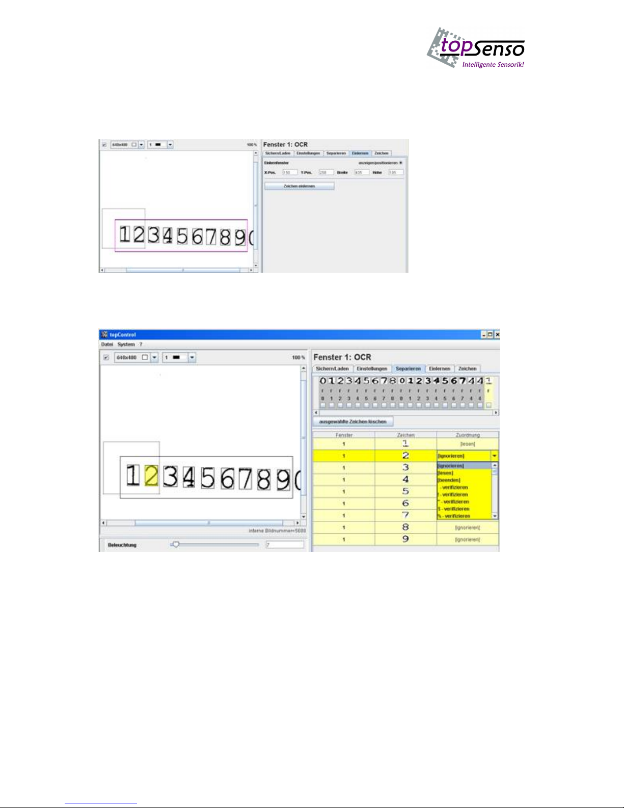
In order to edit additional menu items the character string to be scanned should be read and
the display in the window should be set to at least 320 x 240. If separating is selected the
following interface will be displayed. The buttons display (adjusting window or scanning
window) will display the selected window.
In the figure below the adjusting window is shown in green.
Use the mouse to reset or move the window. This is also possible by directly entering the
coordinates.

- 15 -
The image below shows the scanning window 1.
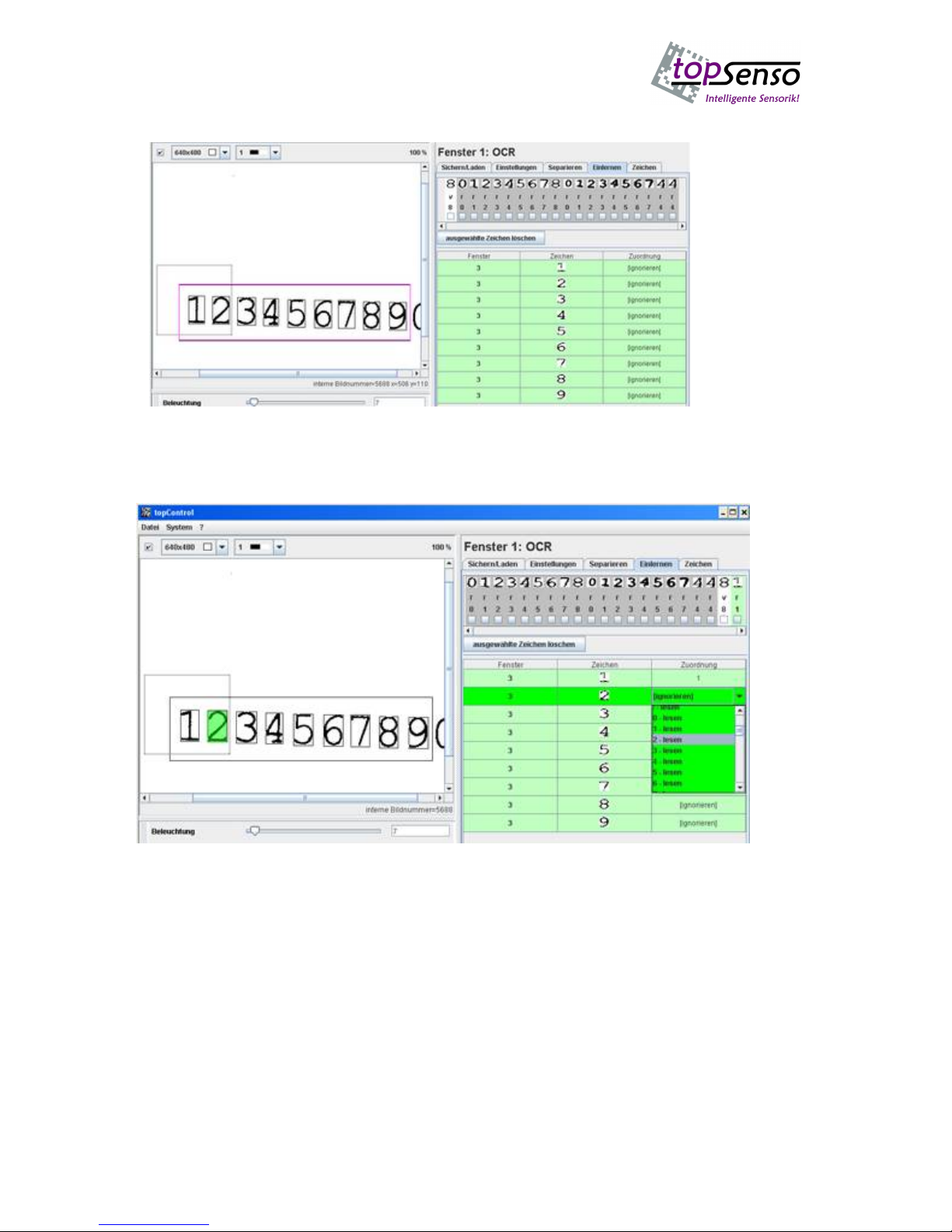
Use the button “Zeichen
Separieren”(Separate
characters) to search and
separate the individual
characters in the
scanning window. All
characters found are
displayed in the user interface.A function can be assigned to every character.The following
functions are available: - “Lesen”(Scanning) (The character on the respective position will be
scanned) – “Verifizieren”(Verify) (Character will only be compared to identical character) –
”Ignorieren”(Ignore) (the character is recognized but ignored) – “Ende”(End) (terminates
the character string).
- 16 -
If a character is highlighted with the mousethe character will be highlighted in yellow in the
image window.Now the required function can be assigned to the character.Using this
procedure a function can be assigned to every single character in the character string. The
current character set of the camera is shown on the top.After all characters have been
assigned the settings are accepted by pressing the button “Übernehmen”(Accept).
In order to be able to scan the characters specified for scanning a character set must be
created.The following describes how to teach the character set.
When choosing the tab “Einlernen” (Teaching) a window in red will be displayed.The
characters in this window are scanned and displayed as a list as for separating.
- 17 -
The following list will be displayed:
The existing
character set
will be
displayed in
the top right
corner.The
function
assignments
appear below
the characters
r= scan, v=
verify.
Characters for
scanning within the character set (marked with “r”) can be deleted.
Now an assignment can be made for the list in the table.
The number 1 has already been included in the character set and is contained in the top
right corner in the character set.
An assignment to the characters is only made for the characters which are to be included in
the character set. The assignment can also, for example, be used to assign a letter to a
Japanese character.
Use the button “Übernehmen”(Accept) to accept all data.
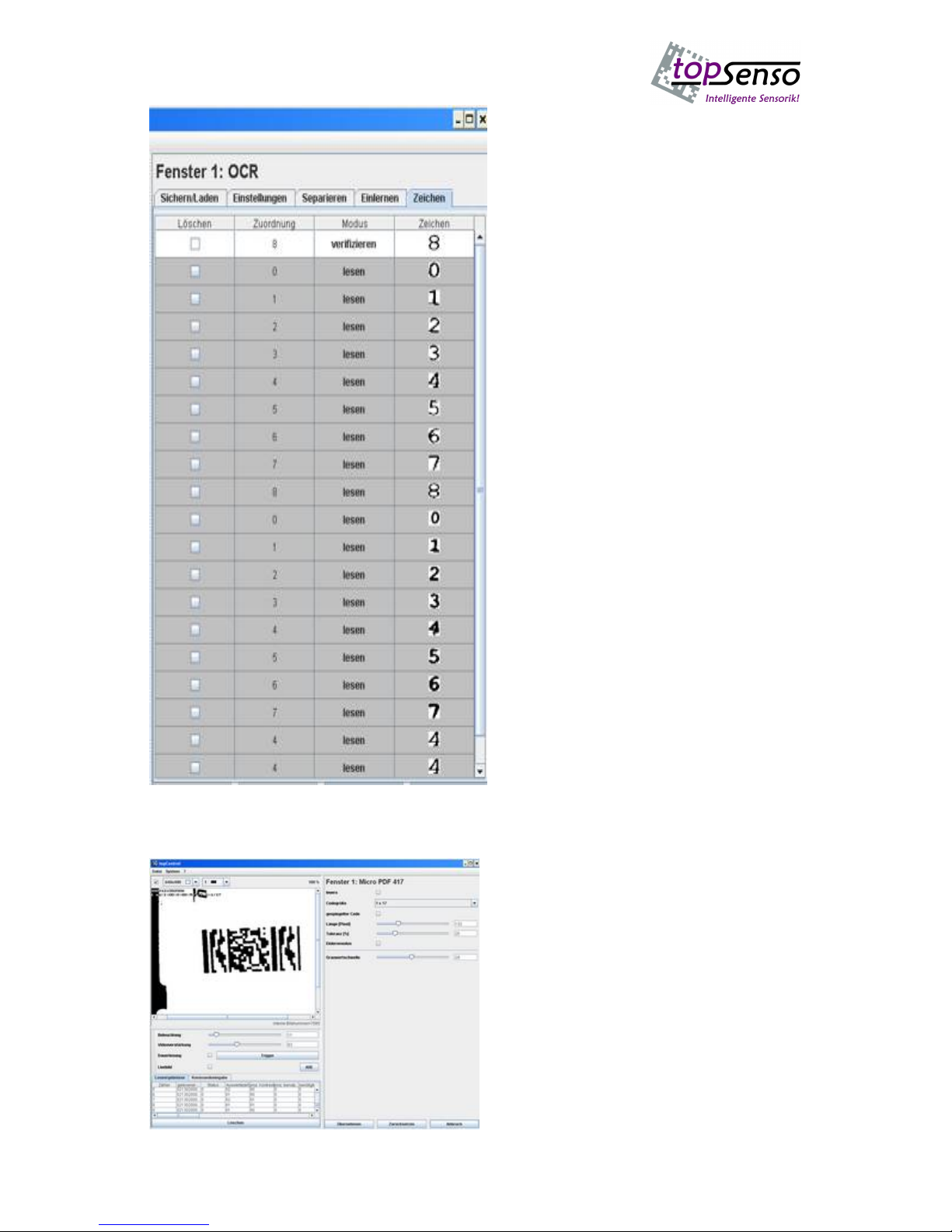
- 18 -
Use the window “Zeichen” (Characters) to
display and edit (delete) the current
character set.
All characters can be deleted apart from
the characters which only have a fixed
position and assignment for verification.
This function is described in modus.
The character set can be up to 40
characters long.
Additional special settings can be set in
the camera. However, they are not
supported by the Windows user interface.
MICRO PDF 417 (stacked bar code)
Another evaluation window is the scanning
of the micro PDF 417 code.

- 19 -
Function window
If more than one evaluation windows
are active AND or OR interconnections
can be made.
If AND is selected all function
windows must have reached a
successful scanning for the successful
signal to be set. If OR is selected only
one function window must have
effected a successful scanning for a
successful signal to be set.
In addition triggering for every
individual window by means of the 2
trigger inputs is possible. Example: If 2
windows are active the different trigger
inputs can be used to initiate a
triggering.In the centre of the picture
below either trigger 1 or trigger 2 can
be selected. This allows realization of
different evaluations at two different
positions.
Interface settings
With selection of the tab
“Schnittstelle”(Interface) the
following settings are possible for
the process interface.
Process interface
Baud rate
Data bits
Parity
Stop bits
Trigger
Polarity
Trigger delay up to
2000 ms
Trigger string (start)
Trigger string (end)
Output signals
Polarity
Pulse length
Output time

- 20 -
A number of options is available for scanning the image and its subsequent evaluation.
1. When applying a trigger signal an evaluation is made by means of a serial trigger
string which can be defined freely.
2. When a certain period has passed after the trigger signal the scanning of the image
starts.
3. After a number of pulses after the trigger input has been set.
4. Within a scanning gate starting with the trigger input
5. Within a scanning gate via soft trigger string start until one soft trigger string is sent
which terminates the scanning procedure.
When the values are on 0 the action is deactivated. Up to 6 unassigned characters can be
selected for the soft trigger start. Also up to 6 characters can be defined for the trigger end
string.
As a default option, a scanning can be initiated by sending the command <STX>TR<CR>.
Options
By selection of the tab “Optionen” (Options) the following basic system settings can be
realized.
Suspending the start-up message
„Trace data matrix code“ after every
successful scanning of the data matrix
code a frame is drawn around the code
and the individual modules are
represented by a dot and the error
correction by a red cross.
Monitor output:
monitor rotated by 90 degrees.
Flash on/off:
the individual flash LEDs can be
switched on or off individually.
Overlay on/off:
permanent scanning, display only
successful scannings
Permanent scanning, but only the
different ones Codes are displayed only
once
Scanning as long as trigger is active
Timeout in ms if value exceeds 0 a
successful scanning must be made
within the time in ms. If not a NIO
signal is emitted.
Match code entry: If the match code is
active the scanned code will be
compared to the reference code. The
reference code can be specified or
taught during the first valid scanning.
Table of contents


(P) user guide")


