annke C11H User manual

USER MANUAL
All rights reserved
Outdoor/Indoor Mini Pan &Tilt Camera

Please check the product configuration and function before you use the product. We do not take responsibility
for any caused by wrong operation. Please keep the instruction book for later use. To ensure a correct use of the
product, please read carefully to fully understand the content. If necessary, please contact the specialist for help. If
the product cannot work or need maintenance, please contact with the distributor or its designated service center.
carefully
Do make sure that you use this product with a proper power source that applies specified voltage and current(110-240VAC,
12V DC). Over range of voltage may damage the unit or cause abnormal performance.
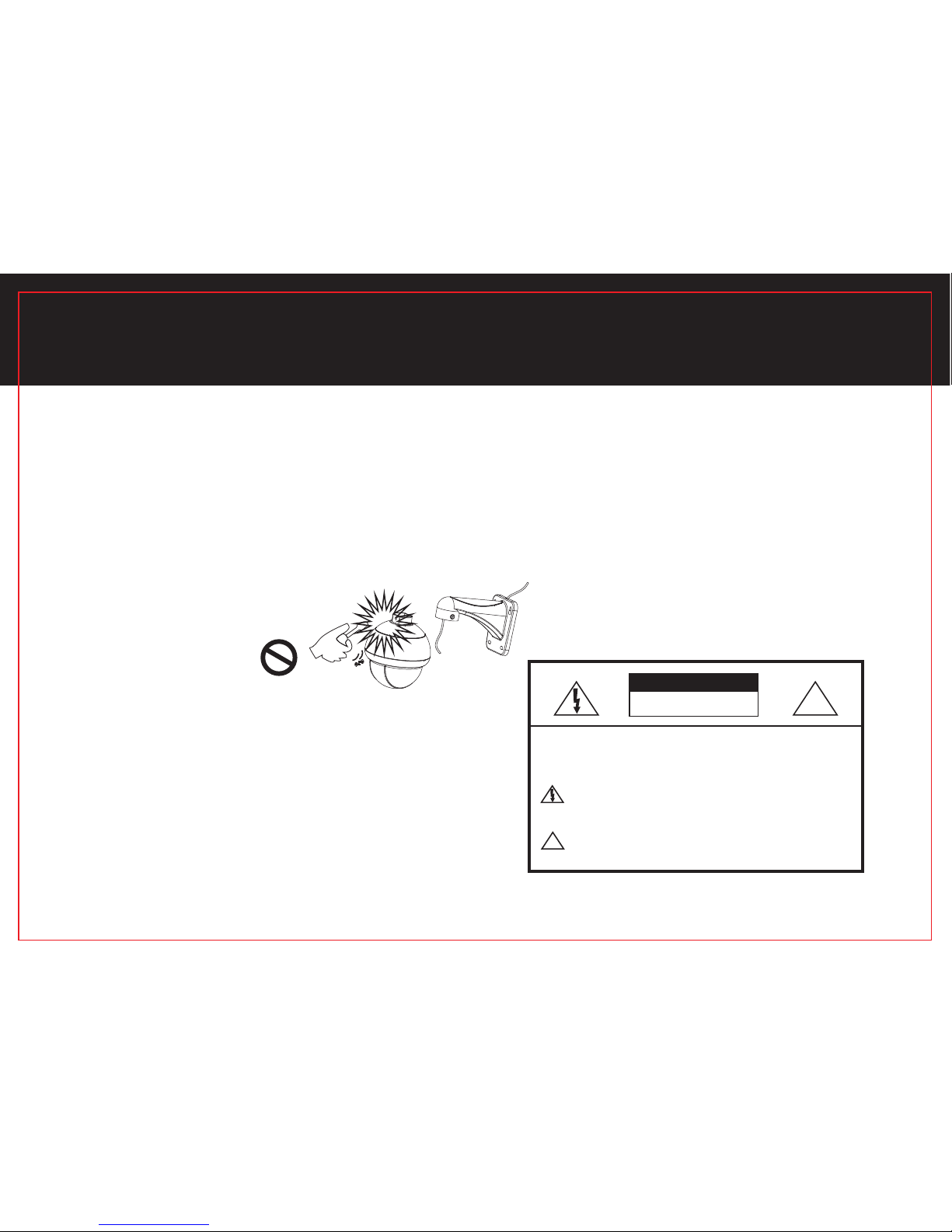
CAUTION! Risk of electrical shock. To prevent electric shock, do not remove screws or cover.
Do not attempt to disassemble camera. There are no user serviceable parts inside. Service should be performed by a
qualified technician only.
Handle camera with care. Do not hit, shake, punch or drop the camera as this would cause damage and prevent proper
operation.
Avoid strong light. Do not expose camera at sun or strong light into the lens as it will degrade image
quality and may cause damage. Camera should ideally be placed out of direct sunlight for improved performance.
expose directly,
Protect from elements. The camera is weatherproof but direct exposure to excessive rain, sun or marine environmental
conditions will degrade its performance and shorten the life of the product.
Avoid excessive moisture in camera or adapters. Do not use strong or abrasive detergents when cleaning camera.
Clean with dry cloth or with mild detergent, gently.
1
THANK YOU FOR YOUR CHOOSING OUR PRODUCT.

2
IMPORTANT SAFEGUARDS..................................................3
PRODUCT OVERVIEW..........................................................5
SCHEMATIC DIAGRAM.........................................................6
INSTALLATION.....................................................................7
CABLES CONNECTING .......................................................10
SETUP ADDRESS................................................................11
APPENDIX A SPECIFFICATIONS..........................................12
APPENDIX B FAQ................................................................15
APPENDIX C KEYBOARD GUIDELINES................................16
APPENDIX D CONTROLLER GUIDELINES ...........................20
TABLE OF CONTENTS

All the safety and operation instruction should be read before the units is operated
Ⅰ Incorrectly connecting the power supply may cause explosion,fire,electric shock, or damage to the product.
Ⅱ Do not attempt to disassemble the camera .In order to prevent electric shock ,do not remove screws or
covers. There are no user-serviceable parts inside.
Ⅲ When installing the camera, fasten it securely and firmly. A falling camera may cause personal injury. Plug
the power cable after installation.
Ⅳ The product can be outdoor and indoor installed, If outdoor installation is needed ,pls add protection
cover should be used and it is absoluted to use it in open air independently,but do not cover it throgh
using inflammables.
Ⅴ If any unusual smells or smoke come from the unit, stop using the product. In such case, Pull out the Power
immediately and contact the service center. Continued use in such a condition may cause fire
or electric shock.
3
IMPORTANT SAFEGUARDS

Ⅵ Do not let the camera expose at the sun or the object with extreme light whatever it is switched on or not .Never let the
camera aim at or monitor bright and standstill object for a long time
Ⅶ Do not use aggressive detergent to clean the main body of the camera .Wipe the dirt with dry cloth .If needed , mild
detergent can be used suitably
Ⅷ If this product fails to work normally, contact the nearest service center. Never attempt to modify this product
in any way. We are not responsible for problems, which caused by unauthorized modifications or attempted repair.
Ⅸ Operate the camera with great care to avoid shock or vibration .If operate incorrectly ,
the camera would be damaged .
Ⅹ This product is designed to be used for normal security &
surveillance place. It is not suitable for extreme cold, hot,
humid or other environments. It can not work properly under
hard condition.
4
IMPORTANT SAFEGUARDS
CAUTION:TO REDUCE THE RISK OF ELECTRIC SHOCK, DO
NOT REMOVE REAR COVER. NO USER SERVICEABLE
PARTSINSIDE. REFER TO QUALIFIED SERVICE PERSONNEL.
This symbol alerts you that important literature concerning
operation and maintenance has been included with
this product.
This symbol indicates high voltage is present inside. It is
dangerous to make any kind of contact with any inside
part of this product.
CAUTION
RISK OF ELECTRIC
SHOCK DO NOT OPEN !
!

Product overview
Watch all directions and keep an eye on the people and places you care about mostly with this camera. With a full 360°
of endless pan and 90°of tilt rotation, and so on (referring to Appendix). it delivers great video quality, reliable operation,
a long operating life and good value. This camera is designed for indoor and outdoor use, and can be mounted for the
perfect viewing angle easily. BNC and DC connections are used for video and power and RS485 connectis for PTZ control.
Installation is easy, just plugs and play.
Package Contents
Please check your camera accessories included in the package. Those components are shown
as below:
Camera Mount Bracket Cables
CCD CAMERA
CCD CAMERA
CCD CAMERA
Package Box
Screws
Package Includes:
·1 PC MINI-PT Weatherproof Pan Tilt Camera
·2 PCS Mount Brackets
·1 PC Camer a Cable
·6 PCS Screws
·1 PC Package Box
·1 PC 100FT Cable with RS485 connector
5
PRODUCT OVERVIEW
The above pictures should be subject to real products.

Lens
IR Leds
Main Body Mount Bracket Ceiling Mounting Wall Mounting
Application Drawing
PT/PTZ Camera
Pan 0°- 360°
Tilt 0°-90°
Internet
6
DVR Monitor
Intelligent Keyboard
SCHEMATIC DIAGRAM

Please read the following instructions before installation:
Ⅱ.Do not allow the cable to be caught in a pinched area, otherwise the electric wire cover may be damaged. This
may cause cable breakdown or fire.
Ⅲ.When installation, don't allow anyone to walk or stand under your installation site, and remove all valuable items.
A dropped camera may cause injury of bystanders or harm to valuable items.
b. Ceiling installation
a.Wall installation
1.The style of the installation
Figure1 Figure2
7
Ⅰ.Please check the location (ceiling or wall) can bear five times of of your camera weight.
HOW TO INSTALL

Figure3 Figure4 Figure5
Figure6
Figure7
Figure8
8
HOW TO INSTALL
2.
Wall installation
Step 1 Open the carton take out the Camera accessiories carefully ( Figure3)
Step 2 Take out system control wires from the bracket ( Figure4)
Step 3 Fix the bracket on the wall ( Figure5)
Step 4 Connect cable connector to camera ( Figure6)
Step 5 Fix camera to the bracket with screws ( Figure7、8)
Steps of installtion
a.

b. Ceiling installation
Open the carton take out camera and accessoires carefully
Step 2 Take out system control wires from the bracket
Step 3 Fix the bracket on the wall ( Figure 9)
Step 4 Connect cable connector to camera( Figure 10)
Step 5 Fix camera to the bracket with bolts ( Figure 11、12)
Step 1
The cable as follow (Figure13),Red is RS485+,Black is RS485-; The power connector is DC maleinterface ;
BNC connector is female (Take care while you connect these connectors) .
3 The outline description
Figure9 Figure10 Figure11 Figure12
9
Figure13
HOW TO INSTALL
Red RS485
Black RS485

To connect cables
1. Connect BNC cable with camera and DVR or Video Balun.
2. Connect power adapter with DC Power connector of camera. And then connect the
power adapter to a power source nearby.
3. Connect RS-485 (Control Wire) with DVR .
NOTE: It is very important that you identify these connecters and make correct connection accordingly.
10
Red=RS485+
Black=RS485-
BNC Cable
DC Cable
Power
Adapter
DVR
CONNECTING CABLES

You can by setup address baudrare and protocol by two ways ,one is to setup by DIP SWITCH , the other one is to
setup camera controller.
How to setup protocol and Baudrate by DIP switch? Open cover ,you can find a DIP switch,
configuration address,protocol and baud rate by DIP switch .
·The address calculation method
Define the DIP switch from 1 to 6 ON is 1, OFF is 0 , and each
of the DIP switch should be multiplied by the multiple as follows define.
0
The first DIP switch is 2
1
The second DIP switch is 2
2
The third DIP switch is 2
3
The fourth DIP switch is 2
4
The fifth DIP switch is 2
5
The sixth DIP switch is 2
The address calculation method as follow:
0 1 2 3 4 5
--×2 + --×2 + --×2 + --×2 + --×2 + --×2 =--
ON DIP
1 2 3 4 5 6 7 8 9 10
11
HOW TO SETUP ADDRESS
DIP 7 DIP8
1200bps ON ON
4800bps
OFF ON
2400bps
ON OFF
9600bps OFF OFF
·DIP 9 is protocol ,ON is pelco-p,OFF is pelco-D
·DIP 7、8 is baud rate
the first the second the third the fourth the fifth the sixth Sum
for example
when the second and the fourth are ON, the others are OFF, So the address calculation as follow
0 1 2 3 4 5
0 ×2 + 1 ×2 + 0 ×2 + 1 ×2 + 0 ×2 + 0 ×2 = 10
so the speed dome camera address is 10

12
APPENDIX A SPECIFICATIONS
SPECIFICATIONS FOR NTSC & PAL
C11H
MODEL
Product type Indoor/Outdoor MINI PTZ camera
Yes
DC 12V
Weatherproof
Power Input
Approx.800MA
Power consumption
1/4" Aptina Color CMOS, 720P
Image device
1280(H)×800(V)
Effective Pixels
Scanning mode
Electronic Shutter
NTSC Standard
720P
PAL Standard
720P
NTSC PAL
1/60s~1/1000000s 1/50s~1/1000000s
White Balance AUTO
AGC Auto/Mode/High Luminance
BLC HLC/OFF
Gamma 0.45
S/N Ratio 52 dB
Video Output 1.0Vp to p75Ω,BNC connector
Usable Illumination 0 lux (When IR LEDs on)
Waterproof level IP66
Lens Electric auto 3-15mm,megapixel

13
APPENDIX A SPECIFICATIONS
SPECIFICATIONS FOR NTSC & PAL
4 pcs Super Leds and 8 pcs Chip-Mounting Leds
About 30m (100FT)
Day/night
80 presets
6 (16 presets/ tour)
Yes
Pan/Tilt/Zoom
Horizontal 0°to 360°
Vertical 0°to 360°
10°per second
Breakpoint memory and power-off protection
RS485
PELCO-D & PELCO-P
1200/2400/4800/9600 bps
IR LEDs Amount
IR Distance
IE LEDs Auto ON/OFF
OSD Menu
PTZ
Preset
Auto tour
Two-point scan
Pan Scan
Tilt Scan
Pan/Tilt Speed
Power-off memory
Communication mode
Communication Protocol
Baud Rate
8 Multi-language:Engilsh/Francis/ Espanol/ Deutsch/
Pyccknn/ Portugues/Japanese/Chinese
PT Control Video matrix,DVR, Keyboard controller, Optional
remote controller
Yes
Guard

Aluminum/White/grey
Ceiling or Wall mounting
DC 12V/2000mA (short cable resistance<0.5Ω)
<24W (When IR LEDs on)
14°F to 122°F (-10~50℃) RH 95% Max
204 195 137mm× ×
1528g
Camera Housing
Installation
Colse Power Supply
Power Consumption
Operating Temperature
Size(package)
Weight
NO
Private Zone
14
APPENDIX A SPECIFICATIONS
SPECIFICATIONS FOR NTSC & PAL STANDARD

Possible Causes
Power supply not enough
Transformer damaged
Problems
No action when power is
switched on
Self-check,lmages with
Power supply
Abnormal Mechanical failure
Remedies
Replace
Bad connection of the power Correct
Replace
motor noise
Camera inclined
Repair
Reinstall
Replace
Camera damaged
Normal self-check but no
Images
Video signal fault
Bad connection of the video
Reinstall
Press to connect well
Replace
Protocol setup is wrong
Normal self-check but out
of control
RS485 bus bad connection
Dome ID setup is wrong
Check the Rs485 connection
Reselect
Preset and Switch ON again
Vague image Bad connection of the video
Power supply not enough
Press to connect well
Replace
Bad control of matrix
Dome camera out of control
Self check error
Bad connection of control
Switch ON again
Press to connect well
Switch ON again
Excessive load,the distance too far Increasing code Distributor
15
APPENDIX B FAQ

1.Select Address of the Camera:[CAM]+[N]+[Enter]
Description:N--No.of camera from 0 to 64
Function:Select the address of the camera to be controlled. When the value N is in conformity with
the address of the Camera, it will be under control.
2.Set the Preset Position:[PRESET]+[N]+[Enter]
Description:N--No.of preset position from 1 to 80
Function:Store current position and refer it as No.N position.
3.Call the Preset Position:[CALL]+[N]+[Enter]
Description:N--No.of preset position from 1 to 80
Function:Transfer the camera to the position of No. N preset position.
4.Cancel the Preset Position:[PRESET]+[N]+[OFF]
Description:N--No.of preset position from 1 to 80
Function:Delete the No. N preset position stored.
5.Set the Cruise Track (PELCO-D, PELCO-P Available):
Enter the Status of Track Setting:[SHOT]+[N]+[ON] (N: No.of track from 1 to 6).
6.Run Cruise Track: [SHOT]+[N]+[Enter]
Description:N--No.of the track from 1 to 6.
Function: Tour the No. N track
7.Stop Cruise Track: [SHOT]+[N]+[OFF]
Description:N--No.of the track from 1 to 6.
Function: Call+128+Enter.
16
APPENDIX C KEYBOARD GUIDELINES

8.Cancel Cruise Track:[SHOT]+[N]+[OFF]
Description:N--No.of the track from 1 to 6
Function: Delete the No. N track
9.Auto Pan ON
·Set the Starting Scan Position: Transfer the speed dome to the
starting scan position, operation [PRESET] +[92] +[ENTER]
·Set the Ending Scan Position: Transfer the speed dome to the
ending scan position, operation [PRESET]+ [93] +[ENTER]
·Run Auto Pan:[CALL]+[92]+ [ENTER] [CALL]+[93]+ [ENTER]
NOTE: the angle of the camera will round less than 180°
·Run Auto Pan [CALL]+[93]+ [ENTER]
NOTE: the angle of the camera will round more than 180°
push the joystick to stop Auto scan or [CALL] +[128] +[ENTER]
10.Auto Track ON A
·Set the Starting Scan Position: Transfer the speed dome to the
starting scan position, operation [AUTO] +[ON]
·Set the Ending Scan Position: Transfer the speed dome to the
ending scan position, operation [AUTO]+ [OFF]
·Run Auto Pan: [AUTO]+[ENTER]
·Stop Track [CALL]+[128]+[ENTER]
Auto Track ON B
You can refer to THE HOME FUNCTION in the APPENDIX D CONTROLLER GUIDELINESS
·set the preset of the HOME [PRESET]+[76] +[ENTER]
·Run Auto pan [CALL]+ [98] +[ENTER]
·stop Track [CALL]+[128]+ [ENTER]
17
APPENDIX C KEYBOARD GUIDELINES

13.Begin 360°Scanning [CALL]+[97]+[ENTER]
14.Stop 360°Scanning [CALL]+[128]+[ENTER] or [CALL]+[96]+[ENTER](two times)
15.The guard functions
Ⅰ.How to set up a guard
Function 1 Reset and keep the guard functions record [PRESET]+[100]+[ENTER]
Function 2 Call the preset position of 80 [PRESET]+[101]+ [ENTER]
Function 3 Auto Pan ON A and keep the guard functions record [PRESET]+[102]+ [ENTER]
Function 4 Auto Pan ON B and keep the guard functions record [PRESET]+[103]+ [ENTER]
Function 5 Run The Cruise Track 1 and keep the guard functions record [PRESET]+[107]+ [ENTER]
Function 6 Call 360°Scanning and keep the guard functions record [PRESET]+[104]+ [ENTER]
Function 7 Call The Track and keep the guard functions record [PRESET]+[106]+ [ENTER]
18
APPENDIX C KEYBOARD GUIDELINES
11.Control the Zoom of the Camera:[WIDE]/[TELE] (Available for the varifocal Lens)
12.Auxiliary Control of the Camera: By combination of [F1] and [ON],[OFF] buttons,you can set
some data of the camera, and functions are listed as follows.
NO.
1
2
3
Control Object
Set Auto Pan (Only conditions
for scan.If start scan, operate as
Item 9 in this paragraph)
Definition of Keyboard Operation
[F1]+N+[ON] [F1]+N+[ON]
< 180°,low speed
< 180°,middle speed
< 180°,high speed
>180°,low speed
>180°,middle speed
> 180°,high speed

19
APPENDIX C KEYBOARD GUIDELINES
Ⅱ.How deletes the guarding position
Function 1 Deletes the guarding position 1 [PRESET]+[100]+ [OFF]
Function 2 Deletes the guarding position 2 [PRESET]+[101]+ [OFF]
Function 3 Deletes the guarding position 3 [PRESET]+[92]+ [OFF]
Function 4 Deletes the guarding position 3 [PRESET]+[103]+ [OFF]
Function 5 Deletes the guarding position 4 [PRESET]+[107]+ [OFF]
Function 6 Deletes the guarding position 5 [PRESET]+[104]+ [OFF]
Function7 Deletes the guarding position 6 [PRESET]+[106]+ [OFF]
Deletes all guarding position [PRESET]+[112]+[OFF]
Ⅲ.Set the time of the guarding position
1 The default is five minutes
It's means that after you have set the guarding position five minutes,
the camera will go to the guarding position one time
2 [PRESET]+[100]+ [OFF] five minutes
It's means that after you have set the guarding position five minutes,
the camera will go to the guarding position one time
3 [PRESET]+[100]+ [OFF] ten minutes
It's means that after you have set the guarding position ten minutes,
the camera will go to the guarding position one time
4 [PRESET]+[100]+ [OFF] thirty minutes
It's means that after you have set the guarding position thirty minutes,
the camera will go to the guarding position one time
5 [PRESET]+[100]+ [OFF] sixty minutes
It's means that after you have set the guarding position sixty minutes,
the camera will go to the guarding position one time
Some special function
Reset and keep the record [CALL]+[94]+ [ENTER]
Reset and delete the record [CALL]+[95]+ [ENTER]
Table of contents
Other annke Security Camera manuals
Popular Security Camera manuals by other brands

BZB Gear
BZB Gear BG-VPTZ-HSU3 user manual

i3 International
i3 International Am52RM user manual

HIK VISION
HIK VISION DS-TCG227-A Series user manual

HIK VISION
HIK VISION DS-2DE2A204IW-DE3(C0)(S6) user manual

HIK VISION
HIK VISION DS-2CE12DFT-PIRXOF28 user manual

HIK VISION
HIK VISION DS-2CD2512F-I Quick operation guide