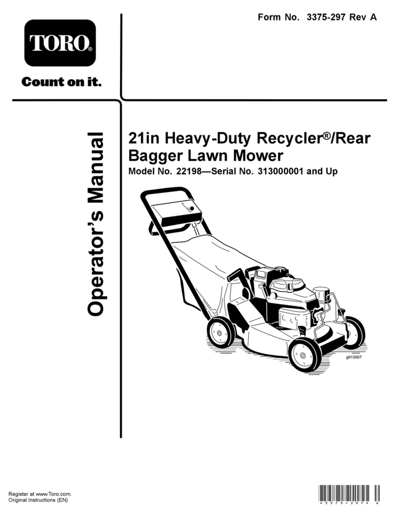
Toro 30381 User manual

FormNo.3364-160RevA
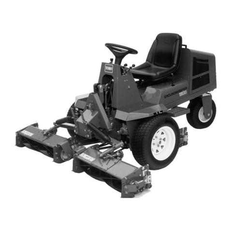
Groundsmaster®7210
TractionUnit
ModelNo.30381—SerialNo.310000001andUp
ToregisteryourproductordownloadanOperator'sManualorPartsCatalogatnocharge,gotowww.Toro.com.OriginalInstructions(EN)

ThisproductcomplieswithallrelevantEuropean
directives,fordetailspleaseseetheseparateproduct
specicDeclarationofConformity(DOC)sheet.
WARNING
CALIFORNIA
Proposition65Warning
Dieselengineexhaustandsomeofits
constituentsareknowntotheStateof
Californiatocausecancer,birthdefects,
andotherreproductiveharm.
Becauseinsomeareastherearelocal,state,orfederal
regulationsrequiringthatasparkarresterbeusedonthe
engineofthismachine,asparkarresterisavailableas
anoption.Ifyourequireasparkarrestor,contactyour
AuthorizedToroServiceDealer.
GenuineTorosparkarrestersareapprovedbytheUSDA
ForestryService.
Important:ItisaviolationofCaliforniaPublic
ResourceCodeSection4442touseoroperate
theengineonanyforest-covered,brush-covered,
orgrass-coveredlandwithoutasparkarrester
mufermaintainedinworkingorder,ortheengine
constricted,equipped,andmaintainedforthe
preventionofre.Otherstatesorfederalareasmay
havesimilarlaws.
Introduction
Important:Usethismanualinconjunction
withthePolarTrackitoranyotherattachments
Operator’sManualforadditionalinformation
onthesafeoperationandmaintenanceofyour
machineandit’sattachments.
Thistractionunitisusedinthesummerwitha
rotary-bladelawnmowerattachmentandinthewinter
withasnowremovalattachmentandisintendedtobe
usedbyprofessional,hiredoperatorsincommercial
applications.
Readthisinformationcarefullytolearnhowtooperate
andmaintainyourproductproperlyandtoavoidinjury
andproductdamage.Youareresponsibleforoperating
theproductproperlyandsafely.
YoumaycontactTorodirectlyatwww.Toro.comfor
productandaccessoryinformation,helpndinga
dealer,ortoregisteryourproduct.
Wheneveryouneedservice,genuineToroparts,or
additionalinformation,contactanAuthorizedService
DealerorToroCustomerServiceandhavethemodel
andserialnumbersofyourproductready.Figure1
identiesthelocationofthemodelandserialnumbers
onthetractionunit.Themodelandserialnumbersfor
thecabareprintedonaplatelocatedoninsidethecab,
ontheframeabovethedoor.Writethenumbersinthe
spaceprovided.
Figure1
1.Modelandserialnumberlocation
ModelNo.
SerialNo.
Thismanualidentiespotentialhazardsandhas
safetymessagesidentiedbythesafetyalertsymbol
(Figure2),whichsignalsahazardthatmaycauseserious
injuryordeathifyoudonotfollowtherecommended
precautions.
Figure2
1.Safetyalertsymbol
Thismanualalsouses2wordstohighlightinformation.
Importantcallsattentiontospecialmechanical
informationandNoteemphasizesgeneralinformation
worthyofspecialattention.
©2009—TheToro®Company
8111LyndaleAvenueSouth
Bloomington,MN554202
Contactusatwww.Toro.com.
PrintedintheUSA.
AllRightsReserved

Contents
Introduction.................................................................2
Safety...........................................................................4
SafeOperatingPractices.......................................4
SafetyandInstructionalDecals.............................6
Setup............................................................................9
1CheckingFluidLevels........................................9
2ActivatingandChargingtheBattery....................9
3InstallingtheMowerDeck/Polar
Trac................................................................11
ProductOverview......................................................19
Controls.............................................................19
Operation...................................................................21
AddingFuel.......................................................21
CheckingtheEngineOilLevel............................22
CheckingtheCoolingSystem..............................22
CheckingtheHydraulicSystem...........................22
ThinkSafetyFirst...............................................22
OperatingtheParkingBrake...............................23
StartingtheEngine.............................................23
DrivingtheMachine...........................................24
StoppingtheMachine/Engine............................25
TheSafetyInterlockSystem................................25
PositioningtheSeat............................................26
UnlatchingtheSeat.............................................27
MovingaNon-functioningMachine...................27
LoadingMachines..............................................28
TransportingtheMachine...................................28
OperatingFrontAttachmentswiththePolar
TracKitInstalled............................................29
Maintenance...............................................................31
RecommendedMaintenanceSchedule(s)................31
DailyMaintenanceChecklist...............................32
PremaintenanceProcedures....................................33
Lubrication.............................................................33
GreasingtheBearingsandBushings....................33
EngineMaintenance...............................................34
AirCleanerMaintenance....................................34
ServicingtheEngineOil.....................................34
FuelSystemMaintenance.......................................36
ServicingtheWaterSeparator.............................36
CleaningtheFuelTank.......................................36
FuelLinesandConnections................................36
BleedingtheFuelSystem....................................36
BleedingAirFromtheInjectors..........................37
ElectricalSystemMaintenance................................38
ServicingtheBattery...........................................38
StoringtheBattery..............................................38
CheckingtheFuses.............................................39
CoolingSystemMaintenance..................................39
CheckingtheCoolingSystem.............................39
CleaningtheRadiator.........................................40
BrakeMaintenance.................................................41
AdjustingtheParkingBrakeInterlock
Switch............................................................41
BeltMaintenance....................................................42
CheckingtheAlternatorBeltTension..................42
ControlsSystemMaintenance.................................42
AdjustingtheControlLeverNeutralInterlock
Switch............................................................42
AdjustingtheControlLeverNeutral
Return............................................................43
AdjustingtheTractionDriveforNeutral.............44
AdjustingtheMaximumGroundSpeed..............45
AdjustingtheTracking........................................45
HydraulicSystemMaintenance...............................46
CheckingtheHydraulicFluidLevel.....................46
ChangingtheHydraulicOilAndFilter................47
Storage.......................................................................48
Machine.............................................................48
Engine...............................................................48
Schematics.................................................................49
ConditionsandProductsCovered.......................52
InstructionsforObtainingWarranty
Service...........................................................52
OwnerResponsibilities.......................................52
ItemsandConditionsNotCovered.....................52
Parts...................................................................52
NoteRegardingDeepCycleBattery
Warranty:.......................................................52
MaintenanceisatOwner’sExpense.....................52
GeneralConditions............................................52
Noteregardingenginewarranty:.........................52
CountriesOtherthantheUnitedStatesor
Canada...........................................................52
3

Safety
ThismachinemeetsorexceedANSIB71.4-2004
specicationsineffectatthetimeofproduction.
Improperuseormaintenancebytheoperatoror
ownercanresultininjury.Toreducethepotential
forinjury,complywiththesesafetyinstructionsand
alwayspayattentiontothesafetyalertsymbol,which
meansCaution,Warning,orDanger—personalsafety
instruction.Failuretocomplywiththeinstructionmay
resultinpersonalinjuryordeath.
SafeOperatingPractices
ThefollowinginstructionsareadaptedfromANSI
B71.4-2004.
Thisproductiscapableofamputatinghandsand
feetandthrowingobjects.Alwaysfollowallsafety
instructionstoavoidseriousinjuryordeath.
Important:Refertothe
R OPS Hard Ca b Operator’ s
Man ual
foradditionalcabsafetyinformation.
Training
•ReadtheOperator’sManualandothertrainingmaterial
carefully.Befamiliarwiththecontrols,safetysigns,
andtheproperuseoftheequipment.
•Neverallowchildrenorpeopleunfamiliarwiththese
instructionstousethemachine.Localregulations
canrestricttheageoftheoperator.
•Neveroperatewhilepeople,especiallychildren,or
petsarenearby.
•Keepinmindthattheoperatororuserisresponsible
foraccidentsorhazardsoccurringtootherpeopleor
theirproperty.
•Donotcarrypassengers.
•Alldriversshouldseekandobtainprofessional
andpracticalinstruction.Suchinstructionshould
emphasize:
–theneedforcareandconcentrationwhen
workingwithride-onmachines;
–controlofaride-onmachineslidingonaslope
willnotberegainedbytheapplicationofthe
controllevers.Themainreasonsforlossof
controlare:
◊insufcienttrackgrip,especiallyonwetgrass,
iceorsnow;
◊beingdriventoofast;
◊inadequatebraking;
◊thetypeofmachineisunsuitableforitstask;
◊lackofawarenessoftheeffectofground
conditions,especiallyslopes;
◊incorrecthitchingandloaddistribution.
Preparation
•Whileoperating,alwayswearsubstantialfootwear
andlongtrousers.Donotoperatetheequipment
whenbarefootorwearingopensandals.
•Thoroughlyinspecttheareawheretheequipment
istobeusedandremoveallobjectswhichmaybe
thrownbythemachine.
•Warning-Fuelishighlyammable.
–Storefuelincontainersspecicallydesignedfor
thispurpose.
–Refueloutdoorsonlyanddonotsmokewhile
refueling.
–Addfuelbeforestartingtheengine.Never
removethecapofthefueltankoraddfuelwhile
theengineisrunningorwhentheengineishot.
–Iffuelisspilled,donotattempttostartthe
enginebutmovethemachineawayfromthe
areaofspillageandavoidcreatinganysourceof
ignitionuntilfuelvaporshavedissipated.
–Replaceallfueltankandcontainercapssecurely.
•Replacefaultysilencers/mufers.
•Beforeusing,alwaysvisuallyinspecttoseethatthe
attachmentsarenotwornordamaged.Replaceworn
ordamagedcomponents.
Operation
•Bealert,slowdownandusecautionwhenmaking
turns.Lookbehindandtothesidebeforechanging
directions.
•Engineexhaustcontainscarbonmonoxide,which
isanodorless,deadlypoisonthatcankillyou.Do
notrunengineindoorsorinanenclosedareawhere
fumescancollect.
•Operateonlyindaylightoringoodarticiallight.
•Lightningcancausesevereinjuryordeath.If
lightningisseenorthunderisheardinthearea,do
notoperatethemachine;seekshelter.
•Beforeattemptingtostarttheengine,disengageall
attachmentclutchesandplacethecontrolleversin
theneutral,lockedposition.
•Whenoperatingneardrop-offsorbodiesofwater,
donotuseonslopesgreaterthan15degrees.
•Usecarewhenpullingloadsorusingheavy
equipment.
4

–Useonlyapproveddrawbarhitchpoints.
–Limitloadstothoseyoucansafelycontrol.
–Donotturnsharply.Usecarewhenreversing.
•Watchoutfortrafcwhencrossingornearroadways.
•Whenusinganyattachments,neverdirectdischarge
ofmaterialtowardbystandersnorallowanyonenear
themachinewhileinoperation.Someattachments,
suchasasnowthrower,arecapableofamputating
handsandfeetandthrowingobjects
•Neveroperatethemachinewithdamagedguards,
shields,orwithoutsafetyprotectivedevicesinplace.
•Donotchangetheenginegovernorsettingsor
overspeedtheengine.Operatingtheengineat
excessivespeedmayincreasethehazardofpersonal
injury.
•Beforeleavingtheoperatorsposition:
–disengagethepowertakeoffandlowerthe
attachments;
–placeinneutralandsettheparkingbrake;
–stoptheengineandremovethekey.
•Ifanattachmentshouldstarttovibrateabnormally,
stopthemachineandcheckimmediatelyforthe
cause.
•Disengagedrivetoattachments,stoptheengine,set
theparkingbrakeandremovetheignitionkey:
–beforeclearingblockagesoruncloggingchute;
–beforechecking,cleaningorworkingonthe
attachment
–afterstrikingaforeignobject.Inspectthe
attachmentfordamageandmakerepairsbefore
restartingandoperatingtheequipment;
–ifthemachinestartstovibrateabnormally(check
immediately).
•Disengagedrivetoattachmentswhentransporting,
notinuseoranytimetheattachmentisintheraised
position.
•Stoptheengineanddisengagedrivetoattachment:
–beforerefuelling;
–beforemakingheightadjustmentunless
adjustmentcanbemadefromtheoperators
position.
•UseonlyToroapprovedattachments.
SlopeOperation
•Rememberthereisnosuchthingasasafeslope.
Travelonslopesrequiresparticularcare.Toguard
againstoverturning:
–donotstoporstartsuddenlywhenonaslope;
–useslowspeedsonslopesandduringtightturns;
–stayalertforhumpsandhollowsandother
hiddenhazards;
•Donotoperateneardrop-offs,ditches,steepbanks
orwater.Tracksdroppingoveredgescancauseroll
overs,whichmayresultinseriousinjury,deathor
drowning.
•Donotoperateonslopeswhereslipperyconditions
couldreducetractionandcouldcauseslidingand
lossofcontrol.
•Donotmakesuddenturnsorrapidspeedchanges.
•Reducespeedanduseextremecautiononslopes.
•Removeormarkobstaclessuchasrocks,treelimbs,
etc.fromtheoperatingarea.Tallgrasscanhide
obstacles.
•Watchforditches,holes,rocks,dips,andrisesthat
changetheoperatingangle,asroughterraincould
overturnthemachine.
•Avoidsuddenstartswhenoperatinguphillbecause
themachinemaytipbackwards.
•Donotoperateoniceincapableofsupportingthe
weightofthismachine.
MaintenanceandStorage
•Keepallnuts,boltsandscrewstighttobesurethe
equipmentisinsafeworkingcondition.
•Neverstoretheequipmentwithfuelinthetank
insideabuildingwherefumesmayreachanopen
ameorspark.
•Allowtheenginetocoolbeforestoringinany
enclosure.
•Toreducetherehazard,keeptheengine,
silencer/mufer,batterycompartmentandfuel
storageareafreeofgrass,leaves,orexcessivegrease.
•Replacewornordamagedpartsforsafety.
•Ifthefueltankhastobedrained,dothisoutdoors.
•Whenmachineistobeparked,storedorleft
unattended,lowertheattachmentunlessapositive
mechanicallockisused.
•UseonlygenuineTororeplacementpartstoensure
thatoriginalstandardsaremaintained.
5

SafetyandInstructional
Decals
Safetydecalsandinstructionsareeasilyvisibletotheoperatorandarelocatednearanyareaof
potentialdanger.Replaceanydecalthatisdamagedorlost.
110-9772
1.Warning—readtheOperator’sManualbeforeoperatingand
donotoperatethismachineunlessyouaretrained.
8.Warning—engagetheparkingbrake,stoptheengineand
removetheignitionkeybeforeleavingthemachine.
2.Crushing/dismembermenthazardofbystanders—donot
carrypassengers,keepbystandersasafedistancefromthe
machine.
9.Cuttinghazardofhandorfoot—removetheignitionkey
andreadtheinstructionsbeforeservicingorperforming
maintenance,keepawayfrommovingparts.
3.Warning—donotusedrugsoralcohol.10.Thrownobjecthazard—keepbystandersasafedistancefrom
themachine;keepalldeectorsandshieldsinplace.
4.Warning—wearhearingprotection.11.Disengage
5.Tipping,dropoffhazard—donotoperatenearwaterdrop-offs,
stayasafedistancefromdrop-offs,slowmachinebefore
turning,donotturnathighspeeds,wearaseatbeltwhen
aROPSisinplace,donotwearaseatbeltwhenROPSis
lowered.
12.Engage
6.Tostarttheengine:clearanydebrisfromtheattachment,
disengagethePTO,movethemotioncontrolleverstothe
neutralposition,engagetheparkingbrake,turntheignitionto
Runandwaitfortheglowpluglighttoturnoff,turntheignition
keytoStart.
13.Parkingbrake
7.ReadtheOperator’sManual.
110-9774
1.Forward3.Slow5.Reverse7.Towvalvelocation;torque
thetowvalvesto6.78±
1.13N⋅m(60±10in-lbs).
2.Fast4.Neutral6.Backward8.ReadtheOperator’s
Manualformore
informationonthehydraulic
oil.
6

110-8253
1.PTO–Off4.Continuousvariable
setting
2.PTO—On5.Slow
3.Fast
110-8254
1.Engine–Stop3.Engine—Start
2.Engine—Run
110-9796
1.ReadtheOperator’sManualforinformationonfuses.
106-6755
1.Enginecoolantunder
pressure.
3.Warning—donottouch
thehotsurface.
2.Explosionhazard—read
theOperator’sManual.
4.Warning—readthe
Operator’sManual.
106-9206
1.Wheeltorquespecications
2.ReadtheOperator’sManual.
7

106-9290
1.Inputs5.Inseat9.Outputs13.Start
2.(notactiveonthismachine)6.PowerT ake-off(PTO)10.PowerT ake-off(PTO)14.Power
3.Hightemperatureshutdown7.ParkingbrakeOff11.Start
4.Hightemperaturewarning8.Neutral12.EnergizetoRun(ETR)
110-9781
1.Warning—readtheOperator’sManual.
2.Poisonandcausticliquid/chemicalburnhazard—keepchildrenasafedistancefromthebattery.
3.Warning—donottouchthehotsurface.
4.Cutting/dismembermenthazard,fanandentanglementhazard,belt—stayawayfrommovingparts.
5.Hydraulicoilinsystemunderpressure,escapinghydraulicoilpenetratingskinhazard,brokenhydrauliclineshazard—wear
protectivehandprotectionwhenhandlinghydraulicsystemcomponents.
8

Setup
LooseParts
Usethechartbelowtoverifythatallpartshavebeenshipped.
ProcedureDescriptionQty.Use
1Nopartsrequired–Checkthehydraulicuid,engineoil,
andcoolantlevels.
2Nopartsrequired–Activateandchargethebattery
3MowerDeckorPolarTracKit(sold
separately)1Installthemowerdeck/PolarTrac.
MediaandAdditionalParts
DescriptionQty.Use
Operator’sManual1Readbeforeoperatingthemachine.
EngineOperator’sManual1Readbeforeoperatingthemachine.
PartsCatalog1Usetolookupandorderparts.
OperatorTrainingMaterials1Viewbeforeoperatingthemachine.
Pre-deliveryInspectionSheet1Readtoverifyproperdelivery.
Enginewarranty1Saveforfutureuse.
1
CheckingFluidLevels
NoPartsRequired
Procedure
1.Checkthehydraulicuidlevelbeforestartingthe
engine,refertoCheckingtheHydraulicFluidLevel
inHydraulicSystemMaintenance.
2.Checktheengineoillevelbeforeandafterstarting
theengine,refertoCheckingtheEngineOilLevel
inEngineMaintenance.
3.Checkthecoolingsystembeforestartingtheengine;
refertoCheckingtheCoolingSysteminCooling
SystemMaintenance.
2
ActivatingandChargingthe
Battery
NoPartsRequired
Procedure
Useonlyelectrolyte(1.265SpecicGravity)toll
batteryinitially.
1.Removethebatteryfromthemachine.
Important:Donotaddelectrolytewhilethe
batteryisinthemachine.Youcouldspillit,
causingcorrosion.
2.Cleanthetopofthebatteryandremovethevent
caps(Figure3).
9

Figure3
1.Ventcaps
3.Carefullylleachcellwithelectrolyteuntiltheplates
arecoveredwithabout1/4inch(6mm)ofuid
(Figure4).
Figure4
1.Electrolyte
4.Allowapproximately20to30minutesforthe
electrolytetosoakintotheplates.Rellasnecessary
tobringtheelectrolytetowithinabout1/4inch(6
mm)ofthebottomofthellwell(Figure4).
WARNING
Chargingthebatteryproducesgassesthatcan
explode.
Neversmokenearthebatteryandkeepsparks
andamesawayfrombattery.
5.Connecta3to4ampbatterychargertothebattery
posts.Chargethebatteryatarateof3to4amps
untilthespecicgravityis1.250orhigherandthe
temperatureisatleast60°F .(16°C)withallcells
gasingfreely.
6.Whenthebatteryischarged,disconnectthecharger
fromtheelectricaloutletandbatteryposts.
Note:Afterthebatteryhasbeenactivated,add
onlydistilledwatertoreplacenormalloss,although
maintenance-freebatteriesshouldnotrequirewater
undernormaloperatingconditions.
WARNING
CALIFORNIA
Proposition65Warning
Batteryposts,terminals,andrelated
accessoriescontainleadandleadcompounds,
chemicalsknowntotheStateofCalifornia
tocausecancerandreproductiveharm.
Washhandsafterhandling.
WARNING
Batteryterminalsormetaltoolscouldshort
againstmetaltractorcomponentscausing
sparks.Sparkscancausethebatterygassesto
explode,resultinginpersonalinjury.
•Whenremovingorinstallingthebattery,do
notallowthebatteryterminalstotouchany
metalpartsofthetractor.
•Donotallowmetaltoolstoshortbetween
thebatteryterminalsandmetalpartsofthe
tractor.
7.Installthebatteryintothemachineandsecureit.
Important:Thebatterymustnotbeableto
moveorwigglewhenpushed.
8.First,installthepositivecable(red)tothepositive
(+)terminalandthenthenegativecable(black)to
thenegative(-)terminalofthebattery.Slidethe
rubberbootoverthepositiveterminaltopreventa
possibleshortfromoccurring.
WARNING
Incorrectbatterycableroutingcoulddamage
themachineandcablescausingsparks.Sparks
cancausethebatterygassestoexplode,
resultinginpersonalinjury.
•Alwaysdisconnectthenegative(black)
batterycablebeforedisconnectingthe
positive(red)cable.
•Alwaysconnectthepositive(red)battery
cablebeforeconnectingthenegative(black)
cable.
10

WARNING
Connectingcablestothewrongpostcould
damagetheelectricalsystemandresultin
personalinjury.
Note:Ensurethatthebatterycablesarerouted
awayfromanysharpedgesormovingparts.
3
InstallingtheMower
Deck/PolarTrac
Partsneededforthisprocedure:
1MowerDeckorPolarTracKit(soldseparately)
InstallingaMowerDeckKit
1.Removethetractionunitfromtheshippingpallet.
2.Placeajackstandundereachwheelmotoranda
oorjackundertherearbumper(Figure5),or
suspendfromaoverheadhoist.
Figure5
1.Rearbumper2.Floorjack
3.Installthesummerdrivetires(Figure6)
Figure6
1.Summerdrivetire
4.Rollthesummerdeckandframeintopositionand
installtheve3/4"bolts,washersandnutsthat
connectthedeckframetotherearframe(Figure7).
Removetheliftcylinderpinstogainaccesstothe
boltsontherighthandside.Torquetheboltsto265
footpounds.
Figure7
1.3mountingbolts(3/4inch),washersandnuts(Leftside)
5.Removetheclevispinsanda5/16"self-tapping
screwpinretainerssecuringtheverticaltubesupport
assembliestotherearofthedeckframe(Figure8).
Figure8
1.Deckframe3.Clevispin&screwpin
retainer
2.Verticaltubesupport
6.Pivotopentheoorplate(Figure9).
11

Figure9
1.Floorplate
7.Slidethedriveshaftontothegearboxshaft
(Figure10).Installtherollpinandtorquethebolts
to175-225inchpounds.
Figure10
1.Driveshaft3.Bolt
2.Gearbox4.Rollpin
8.Routeandconnectthehydraulicpressureandtank
hosestothevalve(Figure11).
Figure11
1.Controlvalve3.Pressurehose
2.Tankhose
9.Installtherearofthedeckliftcylinderontothepivot
pinandsecurewiththeretainingring(Figure12).
10.Securethefrontoftheliftcylindertothemower
framewiththecylinderpinandscrew(Figure12).
Figure12
1.Deckliftcylinder3.Screw
2.Retainingring4.Cylinderpin&screw
11.PositiontheROPSassemblyontotheROPSposts.
Installthebolt,nut,hairpincotterandpinsecuring
eachROPSassemblytotheROPSposts(Figure13).
Note:Ifinstallinganalliedsuppliersmowerdeck,
ROPSKit,partno.117–9179mustbeinstalled.
12

G004634
1
23
4
5
Figure13
1.ROPS4.Bolt&nut
2.Pin5.ROPSpost
3.Cotterpin
12.Startthemachine,raiseandlowerthedeck.Check
forleaksandmakesurethehosesdonotrubagainst
theframe.
InstallingthePolarTracKit
1.Removethetractionunitfromtheshippingpallet.
2.Placeajackstandundereachwheelmotoranda
oorjackundertherearbumper(Figure14)or
suspendfromaoverheadhoist.
Figure14
1.Rearbumper2.Floorjack
3.Removethetwoscrewssecuringthewinterframe
oorplatecovertotheoorandremovetheplate
(Figure15).
Figure15
1.Floorplatecover2.Mountingscrews
4.Carefullyrollthewinterframeassemblyintoposition
whileroutingthedriveshaftthroughtheframetube
(Figure16).
Figure16
1.Driveshaft2.Frametube
Note:Iftherearofthecabisnothighenoughto
clearthecontrolhandles,evenlytightenthejacking
boltsoneachsideofthecabjacktubetoraisethe
rearofthecab(Figure17).
13

Figure17
1.Jackingbolts
5.Routethehosesasfollows:
•Routethetankhoseundertheliftcylinderand
betweenthecylindermountingbracketstothe
valve(Figure18).
•RoutethepressurehosealongsidethePTO
shafttothevalve(Figure18).
Note:Toemphasisthehoserouting,thehosesare
shownwithoutthehosecoversinstalled.
Figure18
1.Tankhose2.Pressurehose
6.Connectthedriveshafttothegearboxshaftinthe
winterframeandtorquethebolts(5/16inch)to
175-225in-lb(20to25N-m).Installtherollpin
(Figure19).
Figure19
1.Pressurehose4.Cabletie
2.Tankhose5.Bolts
3.Hosecover6.Rollpin
7.Adjusttheoorjacktolineupthe1.00inchholes
intheframeandinstallacouplerpinoneachside
(Figure20).
Figure20
1.Couplerpin
8.Adjusttheoorjackorrockthecabwithyourhands
asrequiredtoinstallthebolts(3/4inch)oneachside
(Figure21).Torquetheboltsto265ft-lb(359N-m).
14

Figure21
1.3/4inchbolts2.Couplerpin
Note:Thereartireswillneedtoberemovedto
torquetherearbolts(3/4inch).Aftertorquingthe
framebolts,installthereartiresandtorquelugnuts
to65to85ft-lb(88to115N-m).
9.Insertarubbermountontoeachcabmountatthe
rearmountinglocations(Figure22).
Figure22
1.Cabmount2.Rubbermount
10.Lowerthecabintopositionbyslowlyandevenly
looseningthejackingboltsoneachendofthe
jackingtube(Figure23).
Figure23
1.Jackingbolts2.Cabjacktube
11.Attherearmountingpoints,securethecabtothe
machinewithabolt(1/2x3inches),steelwasher
(1/2x2–1/2inches),rubberwasher(1/2x2–1/2
inches)andnut(1/2inch)(Figure24).Tightenall
fourcabmountboltsuntiltherubbermountsare
compressedtoathicknessof7/8inch(2.2cm).
Figure24
1.Rubbermount2.0.875inch(2.2cm)
12.Tightentheboltsandnutssecuringtherearcab
mountstotheROPSposts(Figure25).Adjustthe
oorjackiftheboltsarebindinganddifcultto
remove.
15

Figure25
1.Cabmount3.Bolts&nuts
2.ROPSpost4.ROPSpost
13.Loosenthejackingboltsandremovethecabjack
tubefromthecutoutsinthecaboor(Figure26).
Figure26
1.Jackingbolts2.Cabjacktube
14.Connectthehydraulicpressurehosetothevalve
hardlineandthetankhosetothevalve(Figure27).
Retainthehoseplugsforthesummerchangeover.
Note:Makesurethehosesarenotekinkedorare
rubbingagainstanymovingparts.
Note:Adjusttheangleofthettingsto
accommodatetheroutingofthehoses.
G009488
1
2
Figure27
1.Pressurehose2.Tankhose
15.Raisetherearofthemachineuntil2jackstandscan
bepositionedunderthereartubeataheightthat
supportsthereartires1to3inches(2.5to7.5cm)
offoftheground.
16.Lowertheoorjacksotherearframerestsonthe
jackstands.Positiontheoorjackunderthecenter
ofthefrontliftarmpivottube.
17.Removetheatwasher(1/2inch)andnut(1/2inch)
installedonthestudonthebogiepivot(Figure28).
Figure28
1.Washer&nutonthebogiepivotstud
18.Raisetheoorjackuntilthefronttiresareoffof
thegroundhighenoughtoinstallthetrackbeneath
themandsupporttheframewithjackstands.
19.Removethefrontandcentertiresfromthewinter
assembly(Figure29).
16

Figure29
1.Fronttire
20.Carefullyliftthetracksovertherearwheelandfront
hubs.Thedirectionofthetrackrotationisprinted
onthetrack.TheVdesignintherubbertrackmust
pointforward.
CAUTION
Thetrackguideshavemanypinchpoints.
Carefullygrasptherubbertrackontheouter
edgesoutboardofthesteelguideswhenmoving
thetrack.
21.Adjusttheoorjacktoasuitableheighttoinstallthe
fronttire.Withahelper,liftthefrontofthetrack
enoughtocarefullyinstallthefronttires(Figure30).
Figure30
22.Adjusttheoorjacktoasuitableheighttoinstallthe
centertire.Liftthecenterofthetrackenoughto
installthecentertire.Torquethelugnutsto65to
85ft-lb(88to115N⋅m).
Figure31
23.Lowertheoorjackuntilthefrontwheelssupport
theframe.Installtheatwashers(1/2inch)and
locknutsonthebogiepivotstud(Figure28)and
torqueto75ft-lb(102N⋅m).
Note:Youmayneedtomovetheoorjacktothe
rearbumpertoraisetherearofthemachinehigh
enoughtoinstalltheatwasherandlocknut.
24.Installthesideaccesscoverswiththescrews
previouslyremoved(Figure32).
Figure32
1.Accesscovers
25.Installthewinterframeoorplatecovertotheoor
withthescrewspreviouslyremoved(Figure33).
17

Figure33
1.Floorplatecover2.Mountingscrews
26.Connectthecabpressureandreturnhosestothe
quickcouplersontherearframemount(Figure34).
Figure34
1.Pressurehose2.Returnhose
27.Removethecapandplugthecabwireharness
connectorintotheharnessontherearframemount
(Figure35).
Figure35
1.Cabwireharness
connector
2.Harnessconnectoronthe
rearframemount
28.Startthemachine.Runtheliftarmupanddownand
checkforhydraulicleaks.Checktheantifreezelevel
andreplenishasrequired.
18

ProductOverview
Controls
Becomefamiliarwithallthecontrolsbeforeyoustart
theengineandoperatethemachine(Figure36).
Figure36
TractorControlPanel
1.Ignitionswitch5.Oilpressurewarninglight
2.Enginecoolant
temperaturewarning
light
6.Chargeindicatorlight
3.Glowpluglight7.Throttlelever
4.Powertakeoff(PTO)
Switch
8.Hourmeter
MotionControlLevers
Themotioncontrolleverscontroltheforwardand
rearwardmotionsaswellastheturningofthemachine.
ParkingBrakeLever
Whenevertheengineisshutoff,engagetheparking
braketopreventaccidentalmovementofthemachine.
Toengagetheparkingbrake,pulltheparkingbrakelever
rearwardandup(Figure37).Toreleasetheparking
brake,pushtheparkingbrakeleverforwardanddown.
Figure37
1.Parkingbrakelever
CAUTION
Donotparkthemachineonaslope.
IgnitionSwitch
Theignitionswitchhasthreepositions:Off,
On/Preheat,andStart.
ThrottleLever
Thethrottlelevercontrolsthespeedoftheengine.
MovingthethrottleleverforwardtowardtheFast
positionincreasestheenginespeed.Movingitrearward
towardtheSlowpositiondecreasestheenginespeed.
Thethrottle,inconjunctionwithmotioncontrollevers,
controlsgroundspeedofthemachine.Alwaysrunthe
machinewiththethrottleintheFastpositionwhen
usingattachments.
PowerTakeOff(PTO)Switch
Thepowertakeoff(PTO)switchstartsandstops
poweredattachments.
HourMeter
Thehourmeterrecordsthenumberofhourstheengine
hasoperated.Itoperateswhenthekeyswitchisinthe
Runposition.Usethesetimesforschedulingregular
maintenance.
GlowPlugLight(OrangeLight)
Theglowplugindicatorlightturnsonwhentheignition
switchisturnedtotheOnposition.Itremainslitfor6
seconds.Whenthelightturnsoff,theengineisready
tobestarted.
19

EngineCoolantTemperatureWarning
Light
Thislightglowsandthepoweredattachmentswillstop
iftheenginecoolanttemperatureishigh.Buttheengine
willcontinuetorun.Ifthemachineisnotstoppedand
thecoolanttemperaturerisesanother20°F,theengine
willstop.
Important:Iftheattachmentshutsdownandthe
temperaturewarninglightison,pushPTOknob
down,drivetoasafeatarea,movethethrottle
levertotheSlowposition,movethemotioncontrol
leversintotheneutrallockedposition,andengage
theparkingbrake.Allowtheenginetoidlefor
severalminuteswhileitcoolstoasafelevel.Stop
theengineandcheckthecoolingsystem;referto
CheckingtheCoolingSysteminCoolingSystem
Maintenance.
ChargeIndicator
Illuminateswhenthesystemchargingcircuit
malfunctions.
OilPressureWarningLight
Theoilpressurewarninglightglowswhentheoil
pressureintheenginedropsbelowasafelevel.Iflow
oilpressureeveroccurs,stoptheengineanddetermine
thecause.Repairthedamagebeforestartingtheengine
again.
FuelGauge
Thefuelgauge(Figure38)indicatesthequantityoffuel
remaininginthefueltanks.
Figure38
1.Fuelgauge
20
Other manuals for 30381
2
This manual suits for next models
1
Table of contents
Other Toro Lawn Mower manuals

Toro
Toro 30553 User manual

Toro
Toro REELMASTER 6500 D User manual

Toro
Toro 74453TE User manual

Toro
Toro Super Recycler 20792 User manual

Toro
Toro 2210 User manual

Toro
Toro 78357 User manual

Toro
Toro Super Bagger 20838 User manual

Toro
Toro ProLine 44448 User manual

Toro
Toro 20380 User manual

Toro
Toro 29730 User manual

Toro
Toro Titan 76605 User manual

Toro
Toro Super Recycler 20039 User manual

Toro
Toro 78370 User manual

Toro
Toro 78268 User manual

Toro
Toro 3806 User manual

Toro
Toro TimeCutter ZS 4200S User manual

Toro
Toro 74633 User manual

Toro
Toro 74386 User manual

Toro
Toro TimeCutter MX 4275T User manual

Toro
Toro 79410 User manual