Toro Groundsmaster 3505-D User manual

FormNo.3426-670RevB
Groundsmaster®3505-DRotary
Mower
ModelNo.30849—SerialNo.403450001andUp
Registeratwww.Toro.com.
OriginalInstructions(EN)*3426-670*B

ThisproductcomplieswithallrelevantEuropean
directives;fordetails,pleaseseetheseparateproduct
specicDeclarationofConformity(DOC)sheet.
ItisaviolationofCaliforniaPublicResourceCode
Section4442or4443touseoroperatetheengineon
anyforest-covered,brush-covered,orgrass-covered
landunlesstheengineisequippedwithaspark
arrester,asdenedinSection4442,maintainedin
effectiveworkingorderortheengineisconstructed,
equipped,andmaintainedforthepreventionofre.
Theenclosedengineowner'smanualissupplied
forinformationregardingtheUSEnvironmental
ProtectionAgency(EPA)andtheCaliforniaEmission
ControlRegulationofemissionsystems,maintenance,
andwarranty.Replacementsmaybeorderedthrough
theenginemanufacturer.
Important:Thisengineisnotequippedwitha
sparkarrestermufer.IfisaviolationofCalifornia
PublicResourceCodeSection4442tooperatethe
engineonanyforest-covered,brush-covered,or
grass-coveredland.Otherstatesorfederalareas
mayhavesimilarlaws.
WARNING
CALIFORNIA
Proposition65Warning
Dieselengineexhaustandsomeofits
constituentsareknowntotheStateof
Californiatocausecancer,birthdefects,
andotherreproductiveharm.
Batteryposts,terminals,andrelated
accessoriescontainleadandlead
compounds,chemicalsknownto
theStateofCaliforniatocause
cancerandreproductiveharm.Wash
handsafterhandling.
Useofthisproductmaycauseexposure
tochemicalsknowntotheStateof
Californiatocausecancer,birthdefects,
orotherreproductiveharm.
Introduction
Thismachineisamulti-purposemachineintended
tobeusedbyprofessional,hiredoperatorsin
commercialapplications.Itisdesignedprimarilyfor
mowinggrassonwell-maintainedlawnsinparks,golf
courses,sportselds,andoncommercialgrounds.
Usingthisproductforpurposesotherthanitsintended
usecouldprovedangeroustoyouandbystanders.
Readthisinformationcarefullytolearnhowtooperate
andmaintainyourproductproperlyandtoavoid
injuryandproductdamage.Youareresponsiblefor
operatingtheproductproperlyandsafely.
Visitwww.Toro.comforproductsafetyandoperation
trainingmaterials,accessoryinformation,helpnding
adealer,ortoregisteryourproduct.
Wheneveryouneedservice,genuineToroparts,or
additionalinformation,contactanAuthorizedService
DealerorToroCustomerServiceandhavethemodel
andserialnumbersofyourproductready.Figure1
identiesthelocationofthemodelandserialnumbers
ontheproduct.Writethenumbersinthespace
provided.
Important:Withyourmobiledevice,youcan
scantheQRcodeontheserialnumberdecal(if
equipped)toaccesswarranty,parts,andother
productinformation.
g259772
Figure1
1.Modelandserialnumberlocation
ModelNo.
SerialNo.
Thismanualidentiespotentialhazardsandhas
safetymessagesidentiedbythesafety-alertsymbol
(Figure2),whichsignalsahazardthatmaycause
seriousinjuryordeathifyoudonotfollowthe
recommendedprecautions.
g000502
Figure2
1.Safety-alertsymbol
Thismanualuses2wordstohighlightinformation.
Importantcallsattentiontospecialmechanical
informationandNoteemphasizesgeneralinformation
worthyofspecialattention.
©2019—TheToro®Company
8111LyndaleAvenueSouth
Bloomington,MN554202
Contactusatwww.Toro.com.
PrintedintheUSA
AllRightsReserved

Contents
Safety.......................................................................4
GeneralSafety...................................................4
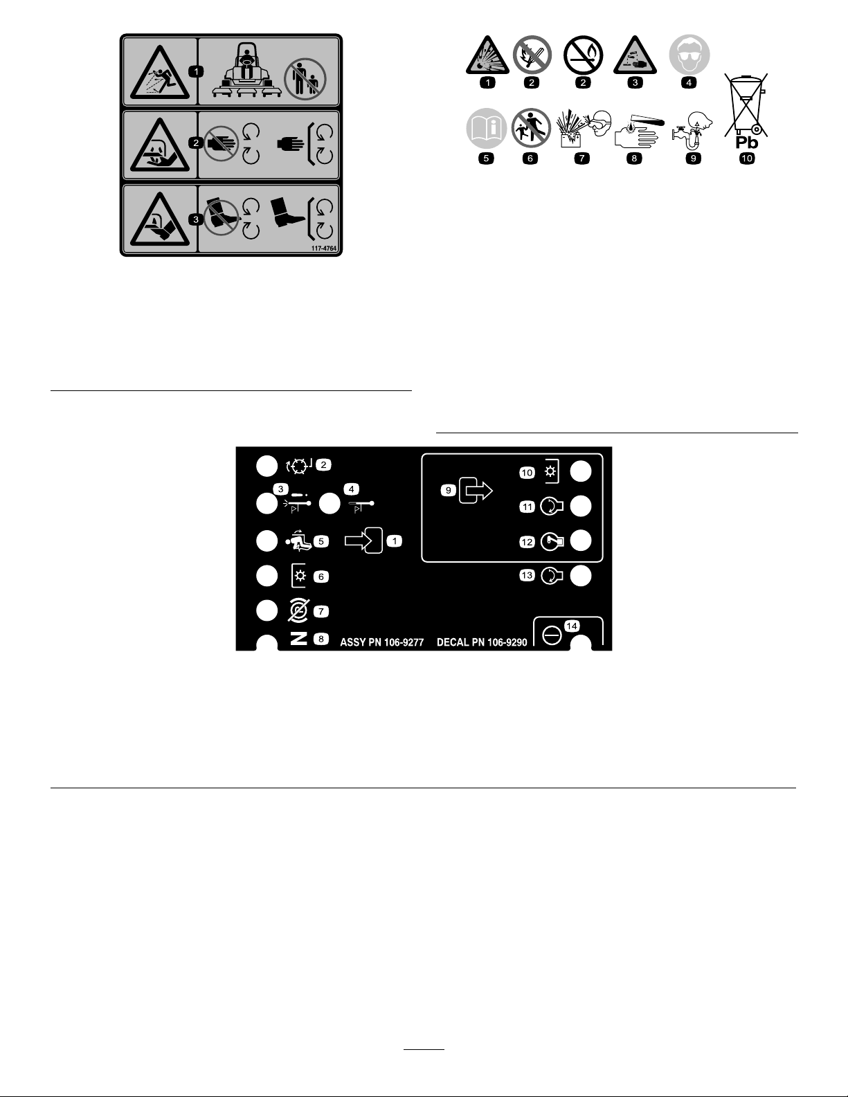
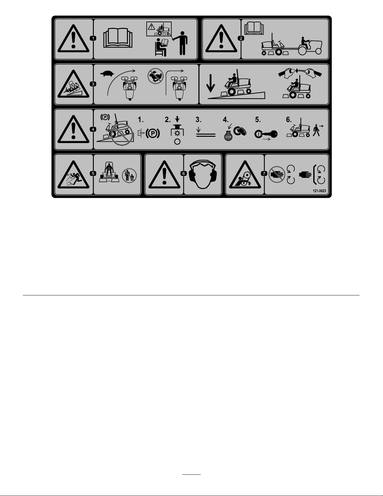
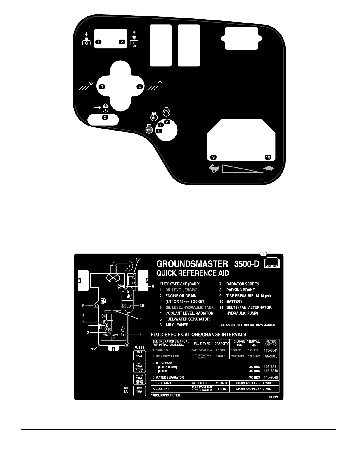
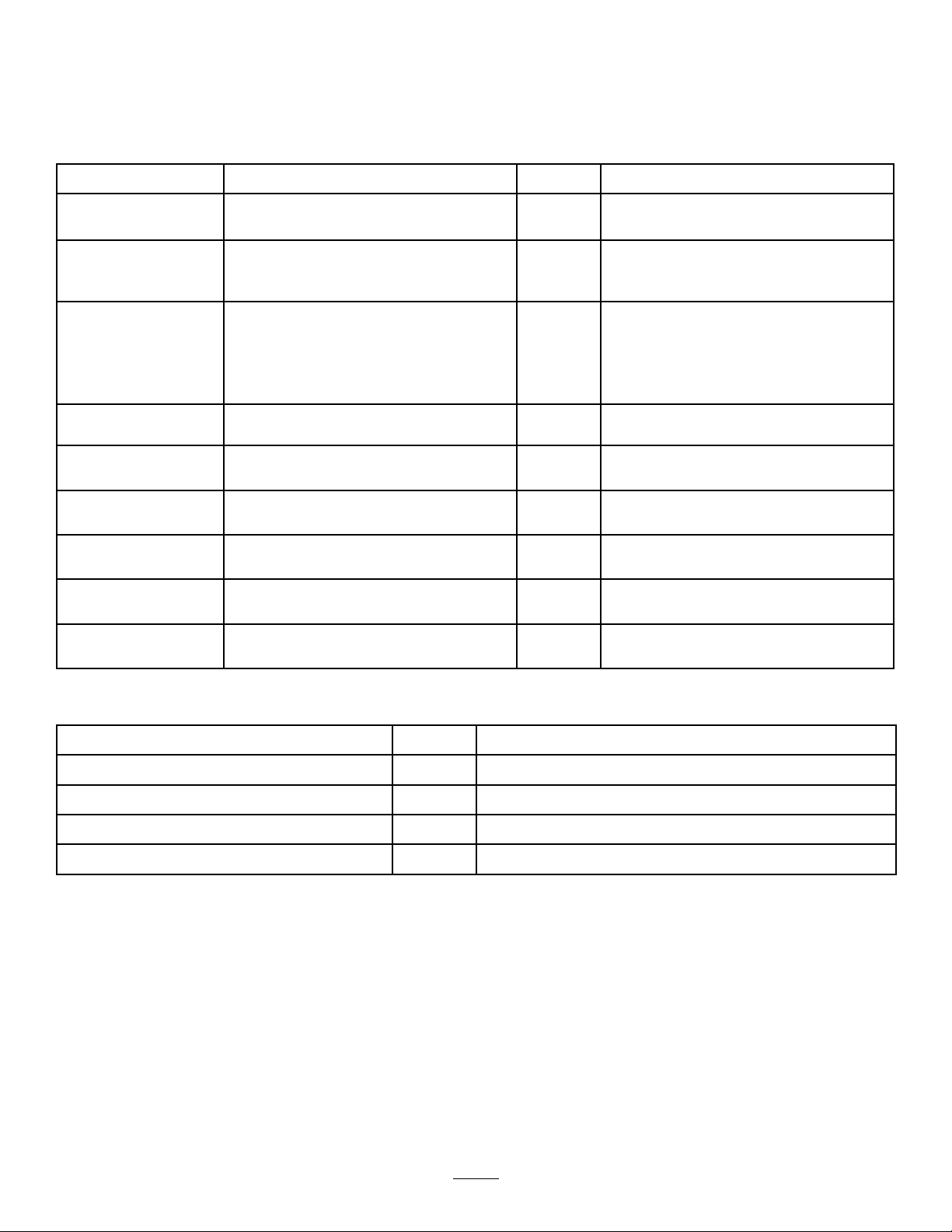
SafetyandInstructionalDecals..........................5
Setup......................................................................10
1Activating,Charging,andConnectingthe
Battery...........................................................11
2InstallingtheCEDecal...................................12
3InstallingtheHoodLatch................................12
4InstallingtheExhaustGuard..........................14
5AdjustingtheLiftArms...................................15
6AdjustingtheCarrierFrame...........................16
7AdjustingtheHeightofCut.............................17
8AdjustingtheRollerScraper...........................18
9InstallingtheMulchingBafe..........................18
ProductOverview...................................................19
Controls...........................................................19
Specications..................................................22
Attachments/Accessories.................................23
BeforeOperation.................................................23
BeforeOperationSafety...................................23
AddingFuel......................................................24
CheckingtheEngine-OilLevel..........................25
CheckingtheCoolingSystem...........................25
CheckingtheHydraulicSystem........................25
SelectingaBlade..............................................25
ChoosingAccessories......................................26
CheckingtheSafety-InterlockSystem..............26
DuringOperation.................................................27
DuringOperationSafety...................................27
StartingtheEngine...........................................28
ShuttingOfftheEngine.....................................28
Standard-ControlModule(SCM)......................29
OperatingTips.................................................31
AfterOperation....................................................32
GeneralSafety.................................................32
HaulingtheMachine.........................................32
LocatingtheTie-DownPoints...........................33
PushingorTowingtheMachine........................33
Maintenance...........................................................34
MaintenanceSafety..........................................34
RecommendedMaintenanceSchedule(s)...........34
DailyMaintenanceChecklist.............................36
Pre-MaintenanceProcedures..............................37
PreparingtheMachineforMaintenance............37
RemovingtheHood..........................................37
UsingtheCuttingUnitServiceLatch
......................................................................37
Lubrication..........................................................38
GreasingtheBearingsandBushings................38
EngineMaintenance...........................................40
EngineSafety...................................................40
ServicingtheAirCleaner..................................40
ServicingtheEngineOil....................................42
FuelSystemMaintenance...................................43
DrainingtheFuelT ank......................................43
ServicingtheWaterSeparator..........................43
BleedingtheFuelSystem.................................44
BleedingAirfromtheInjectors..........................44
ElectricalSystemMaintenance...........................45
ElectricalSystemSafety...................................45
ServicingtheBattery.........................................45
ServicingtheFuses..........................................45
DriveSystemMaintenance..................................46
CheckingtheTirePressure...............................46
CheckingtheTorqueoftheWheel-Lug
Nuts..............................................................46
AdjustingtheTractionDriveforNeutral.............46
CoolingSystemMaintenance..............................47
CoolingSystemSafety.....................................47
CheckingtheCoolingSystem...........................47
CleaningtheCoolingSystem............................48
BrakeMaintenance.............................................49
AdjustingtheParkingBrake..............................49
BeltMaintenance................................................49
ServicingtheEngineBelts................................49
ControlsSystemMaintenance.............................50
AdjustingtheThrottle........................................50
HydraulicSystemMaintenance...........................51
HydraulicSystemSafety...................................51
ServicingtheHydraulicFluid............................51
CuttingUnitMaintenance.....................................54
SeparatingtheCuttingUnitsfromthe
TractionUnit..................................................54
MountingtheCuttingUnitstotheTraction
Unit...............................................................55
ServicingtheBladePlane.................................55
ServicingtheFrontRoller.................................56
BladeMaintenance..............................................57
BladeSafety.....................................................57
ServicingtheBlade...........................................57
Storage...................................................................59
StorageSafety..................................................59
PreparingtheMachineforStorage...................59
StoringtheCuttingUnits...................................59
3

Safety
Thismachinehasbeendesignedinaccordancewith
ENISO5395andANSIB71.4-2017.
GeneralSafety
Thisproductiscapableofamputatinghandsand
feetandofthrowingobjects.Alwaysfollowallsafety
instructionstoavoidseriouspersonalinjury.
•Readandunderstandthecontentsofthis
Operator’sManualbeforestartingtheengine.
•Useyourfullattentionwhileoperatingthe
machine.Donotengageinanyactivitythat
causesdistractions;otherwise,injuryorproperty
damagemayoccur.
•Donotoperatethemachinewithoutallguards
andothersafetyprotectivedevicesinplaceand
functioningproperlyonthemachine.
•Keepyourhandsandfeetawayfromrotating
parts.Keepclearofthedischargeopening.
•Keepbystandersandchildrenoutoftheoperating
area.Neverallowchildrentooperatethemachine.
•Shutofftheengine,removethekey(ifequipped),
andwaitforallmovementtostopbeforeyouleave
theoperator’sposition,Allowthemachinetocool
beforeadjusting,servicing,cleaning,orstoringit.
Improperlyusingormaintainingthismachinecan
resultininjury.Toreducethepotentialforinjury,
complywiththesesafetyinstructionsandalways
payattentiontothesafety-alertsymbol,which
meansCaution,Warning,orDanger—personalsafety
instruction.Failuretocomplywiththeseinstructions
mayresultinpersonalinjuryordeath.
4

SafetyandInstructionalDecals
Safetydecalsandinstructionsareeasilyvisibletotheoperatorandarelocatednearanyarea
ofpotentialdanger.Replaceanydecalthatisdamagedormissing.
decal93-6681
93-6681
1.Cutting/dismemberment—hazard,fan-stayawayfrom
movingparts.
decal93-7276
93-7276
1.Explosionhazard—weareyeprotection.
2.Causticliquid/chemicalburnhazard—toperformrstaid,
ushwithwater.
3.Firehazard—nore,openames,orsmoking.
4.Poisonhazard—keepchildrenawayfromthebattery.
decal93-7818
93-7818
1.Warning—readtheOperator'sManualforinstructionson
torquingthebladebolt/nutto115-149N∙m(85-110ft-lb).
99-3444
decal99-3444
99-3444
1.Transportspeed—fast2.Mowingspeed—slow
decal106-6755
106-6755
1.Enginecoolantunder
pressure
3.Warning—donottouchthe
hotsurface.
2.Explosionhazard—read
theOperator'sManual.
4.Warning—readthe
Operator'sManual.
decal117-3270
117-3270
1.Warning—donottouchthehotsurface.
2.Cutting/dismembermenthazard,hand;entanglement
hazard,belt—stayawayfrommovingparts,keepallguards
andshieldsinplace.
decal133-8062
133-8062
5

decal117-4764
117-4764
1.Thrownobjecthazard—keepbystandersaway.
2.Cuttinghazardofhand,mowerblade—stayawayfrom
movingparts;keepallguardsandshieldsinplace.
3.Cuttinghazardoffoot,mowerblade—stayawayfrom
movingparts;keepallguardsandshieldsinplace.
decalbatterysymbols
BatterySymbols
Someorallofthesesymbolsareonyourbattery.
1.Explosionhazard6.Keepbystandersaway
fromthebattery.
2.Nore,opename,or
smoking
7.Weareyeprotection;
explosivegasescan
causeblindnessandother
injuries.
3.Causticliquid/chemical
burnhazard
8.Batteryacidcancause
blindnessorsevereburns.
4.Weareyeprotection.9.Flusheyesimmediately
withwaterandgetmedical
helpfast.
5.ReadtheOperator's
Manual.
10.Containslead;donot
discard
decal106-9290
106-9290
1.Inputs5.Inseat9.Outputs13.Start
2.Notactive6.Powertake-off(PTO)10.Powertake-off(PTO)14.Power
3.High-temperature
shutdown
7.Parkingbrakeoff11.Start
4.High-temperaturewarning8.Neutral12.Energizetorun(ETR)
6

decal121-3627
121–3627
1.Height-of-cutsettings
decal121-3598
121-3598
Note:Thismachinecomplieswiththeindustrystandard
stabilitytestinthestaticlateralandlongitudinaltestswiththe
maximumrecommendedslopeindicatedonthedecal.Reviewthe
instructionsforoperatingthemachineonslopesintheOperator’s
Manualaswellastheconditionsinwhichyouwouldoperatethe
machinetodeterminewhetheryoucanoperatethemachineinthe
conditionsonthatdayandatthatsite.Changesintheterraincan
resultinachangeinslopeoperationforthemachine.Ifpossible,
keepthecuttingunitsloweredtothegroundwhileoperatingthe
machineonslopes.Raisingthecuttingunitswhileoperatingon
slopescancausethemachinetobecomeunstable.
1.Tippinghazard—donotdriveacrossslopesgreaterthan
17°.
7

decal121-3623
121-3623
1.Warning—readtheOperator'sManual;donotoperatethe
machineunlessyouhavereceivedtraining.
5.Thrownobjecthazard—keepbystandersaway.
2.Warning—readtheOperator'sManualbeforetowingthe
machine.
6.Warning—wearhearingprotection.
3.Tippinghazard—slowthemachinebeforeturning;when
drivingonslopes,keepthecuttingunitsloweredandyour
seatbeltfastened.
7.Entanglementhazard—keepawayfrommovingparts;keep
allguardsandshieldsinplace.
4.Warning—donotparkonslopes;engagetheparkingbrake,
stopthecuttingunits,lowertheattachments,shutoffthe
engine,andremovethekeyfromtheignitionbeforeleaving
themachine.
8

decal121-3619
121-3619
1.PTO—Disengage6.Engine—Shutoff
2.PTO—Engage7.Engine—Run
3.Lowerthecuttingunits.8.Engine—Start
4.Raisethecuttingunits.9.Fast
5.Lock10.Slow
decal138-6974
138-6974
1.ReadtheOperator’sManual.
9

Setup
LooseParts
Usethechartbelowtoverifythatallpartshavebeenshipped.
ProcedureDescriptionQty.Use
1Nopartsrequired–Activate,charge,andconnectthe
battery.
Safetydecal1
Productionyeardecal1
2CEMarkdecal1
InstalltheCEdecals(ifrequired).
Hood-latchbracket1
Rivet2
Washer1
Screw(1/4x2inches)1
3
Locknut(1/4inch)1
Installthehoodlatch(CEmachines
only).
Exhaustguard1
4Self-tappingscrew4Installtheexhaustguard(CEonly).
5Nopartsrequired–Adjusttheliftarms.
6Nopartsrequired–Adjustthecarrierframe.
7Nopartsrequired–Adjusttheheightofcut.
8Nopartsrequired–Adjusttherollerscraper(optional).
9Nopartsrequired–Installthemulchingbafe(optional).
MediaandAdditionalParts
DescriptionQty.Use
Operator'sManual1Reviewitbeforeoperatingthemachine.
Engineowner'smanual1Useittoreferenceengineinformation.
DeclarationofConformity1
Ignitionkeys2Starttheengine.
Note:Determinetheleftandrightsidesofthemachinefromthenormaloperatingposition.
10

1
Activating,Charging,and
ConnectingtheBattery
NoPartsRequired
Procedure
Note:Ifthebatteryisnotlledwithelectrolyteor
activated,purchasebulkelectrolytewith1.26specic
gravityfromalocalbattery-supplyoutletandadditto
thebattery.
DANGER
Batteryelectrolytecontainssulfuricacid
whichisfatalwhenconsumedandcauses
severeburns.
•Donotdrinkelectrolyteandavoidcontact
withskin,eyes,orclothing.Wearsafety
glassestoshieldyoureyesandrubber
glovestoprotectyourhands.
•Fillthebatterywherecleanwaterisalways
availableforushingtheskin.
1.Removethebatterycover(Figure3).
g031567
Figure3
1.Batterycover
2.Removethellercapsfromthebatteryand
slowlylleachcelluntiltheelectrolyteisjust
abovetheplates.
3.Installthellercapsandconnecta3to4A
batterychargertothebatteryposts.
Note:Chargethebatteryatarateof3to4A
for4to8hours.
WARNING
Chargingthebatteryproducesgasses
thatcanexplode.
•Keepsparksandamesawayfrom
battery.
•Neversmokenearthebattery.
4.Whenthebatteryischarged,disconnectthe
chargerfromtheelectricaloutletandbattery
posts.
5.Removethellercaps.
6.Slowlyaddelectrolytetoeachcelluntilthelevel
isuptothellring.
Important:Donotoverllthebattery.
Electrolytewilloverowontootherparts
ofthemachineandseverecorrosionand
deteriorationwillresult.
7.Installthellercaps.
8.Installthepositivecable(red)tothepositive(+)
terminalandthenegativecable(black)tothe
negative(–)terminalofthebatteryandsecure
themwiththeboltsandnuts(Figure4).
Note:Ensurethatthepositive(+)terminalisall
thewayontothepostandthecableispositioned
snugtothebattery.Thecablemustnotcontact
thebatterycover.
WARNING
Incorrectbatterycableroutingcould
damagethetractorandcables,causing
sparks.Sparkscancausethebattery
gasestoexplode,resultinginpersonal
injury.
•Alwaysdisconnectthenegative
(black)batterycablebefore
disconnectingthepositive(red)
cable.
•Alwaysconnectthepositive(red)
batterycablebeforeconnectingthe
negative(black)cable.
11

g031568
Figure4
1.Negative(–)batterycable2.Positive(+)batterycable
Important:Ifyoueverremovethebattery,
installthebattery-clampboltswiththebolt
headspositionedonthebottomsideand
thenutsonthetopside.Iftheclampbolts
arereversed,theymayinterferewiththe
hydraulictubeswhenshiftingthecutting
units.
9.CoatbothbatteryconnectionswithGrafo112X
(skinover)grease(ToroPartNo.505-47),
petroleumjelly,orlightgreasetoprevent
corrosion.
10.Slidetherubberbootoverthepositiveterminal
topreventapossibleshortfromoccurring.
11.Installthebatterycover.
2
InstallingtheCEDecal
Partsneededforthisprocedure:
1Safetydecal
1Productionyeardecal
1CEMarkdecal
Procedure
IfthismachinewillbeusedforCE,afxthe
CE-warningdecaloverthecorrespondingEnglish
warningdecal.
g278676
Figure5
1.CEwarningdecal
IfthismachinewillbeusedforCE,afxtheproduction
yeardecalandCEmarkdecalnexttotheserialplate
(Figure6).
g278675
Figure6
1.Serialplate3.Productionyeardecal
2.CEmarkdecal
12

3
InstallingtheHoodLatch
CEMachinesOnly
Partsneededforthisprocedure:
1Hood-latchbracket
2Rivet
1Washer
1Screw(1/4x2inches)
1Locknut(1/4inch)
Procedure
1.Unhookthehoodlatchfromthehood-latch
bracket.
2.Removethe2rivetssecuringthehood-latch
brackettothehood(Figure7).
g012628
Figure7
1.Hood-latchbracket2.Rivets
3.Removethehood-latchbracketfromthehood.
4.Whilealigningthemountingholes,positionthe
CElockbracketandthehood-latchbracketonto
thehood(Figure8).
Note:Thelockbracketmustbeagainstthe
hood.Donotremovetheboltandnutfromthe
lock-bracketarm.
g012629
Figure8
1.CElockbracket2.Boltandnut
5.Alignthewasherswiththeholesontheinsideof
thehood.
6.Rivetthebracketsandthewasherstothehood
(Figure8).
7.Hookthelatchontothehood-latchbracket
(Figure9).
g012630
Figure9
1.Hoodlatch
8.Installtheboltintotheotherarmofthe
hood-latchbrackettolockthelatchinposition
(Figure10).Tightentheboltbutdonottighten
thenut.
13

g012631
Figure10
1.Bolt3.Armofhood-latchbracket
2.Nut
4
InstallingtheExhaust
Guard
CEModelsOnly
Partsneededforthisprocedure:
1Exhaustguard
4Self-tappingscrew
Procedure
1.Positiontheexhaustguardaroundthemufer
whilealigningthemountingholeswiththeholes
intheframe(Figure11).
g008875
Figure11
1.Exhaustguard
2.Securetheexhaustguardtotheframewith4
self-tappingscrews(Figure11).
14

5
AdjustingtheLiftArms
NoPartsRequired
Procedure
1.Starttheengine,raisethecuttingunits,and
ensurethattheclearancebetweeneachliftarm
andtheoor-platebracketis5to8mm(0.18to
0.32inch)asshowninFigure12.
g031571
Figure12
Cuttingunitsremovedforclarity
1.Floor-platebracket3.Liftarm
2.Clearance
Iftheclearanceisnotinthisrange,adjust
itasfollows:
A.Backoffthestopbolts(Figure13).
g031572
Figure13
1.Stopbolt3.Liftarm
2.Clearance
B.Backoffthejamnutonthecylinder(Figure
14).
g031573
Figure14
1.Jamnut2.Frontcylinder
C.Removethepinfromtherodendandrotate
theclevis.
D.Installthepinandchecktheclearance.
Note:Repeattheprocedureifrequired.
E.Tightentheclevisjamnut.
2.Ensurethattheclearancebetweeneachliftarm
andstopboltis0.13to1.02mm(0.005to0.040
inch)asshowninFigure13.
Note:Iftheclearanceisnotinthisrange,adjust
thestopboltstoattaintheproperclearance.
3.Starttheengine,raisethecuttingunits,and
ensurethattheclearancebetweenthewear
straponthetopoftherear-cutting-unitwearbar
andthebumperstrapis0.51to2.54mm(0.02
to0.10inch)asshowninFigure15.
g031574
Figure15
1.Wearbar2.Bumperstrap
Iftheclearanceisnotinthisrange,adjust
therearcylinderasfollows:
Note:Iftherear-liftarmclunksduringtransport,
youcanreduceclearance.
A.Lowerthecuttingunitsandbackoffthejam
nutonthecylinder(Figure16).
15

g031575
Figure16
1.Rearcylinder2.Adjustingnut
B.Graspthecylinderrodclosetothenutwith
apliersandrag,androtatetherod.
C.Raisethecuttingunitsandcheckthe
clearance.
Note:Repeattheprocedureifrequired.
D.Tightentheclevisjamnut.
Important:Lackofclearanceatthefrontstopsor
rearwearbarcoulddamagetheliftarms.
6
AdjustingtheCarrierFrame
NoPartsRequired
AdjustingtheFrontCuttingUnits
Thefrontandrearcuttingunitsrequiredifferent
mountingpositions.Thefrontcuttingunithas2
mountingpositionsdependingonwhatheightofcut
anddegreeofcuttingunitrotationyoudesire.
1.Forheightsofcutinthe2to7.6cm(3/4to3
inches)range,mountthefrontcarrierframesin
thelower,frontmountingholes(Figure17).
Note:Thispermitsmoreuptravelofthecutting
unitsrelativetothemachinewhenapproaching
suddenchangesinuphillterrain.Itdoes,
however,limittheclearanceofthechamberto
thecarrierwhencrestingsharp,smallhills.
g031576
Figure17
1.Upper,frontcuttingunit
mountinghole
3.Rearcuttingunitmounting
hole
2.Lower,frontcuttingunit
mountinghole
2.Forheightsofcutinthe6.3to10cm(2-1/2to4
inches)range,mountthefrontcarrierframesin
theupper,frontmountingholes(Figure17).
Note:Thisincreasesthechambertocarrier
clearanceduetothehigherpositionofthe
cuttingchamber,butcausesthecuttingunitto
reachitsmaximumuptravelmorequickly.
AdjustingtheRearCuttingUnit
Thefrontandrearcuttingunitsrequiredifferent
mountingpositions.Therearcuttingunithas1
mountingpositionforproperalignmentwiththe
Sidewinder®unitundertheframe.
Forallheightsofcut,mounttherearcuttingunitinthe
rearmountingholes(Figure17).
16

7
AdjustingtheHeightofCut
NoPartsRequired
Procedure
Important:Thiscuttingdeckoftencuts
approximately6mm(1/4inch)lowerthanareel
cuttingunitwiththesamebenchsetting.Itmay
benecessarytohavetherotarycuttingdecks
benchset6mm(1/4inch)abovethatofthereels
cuttinginthesamearea.
Important:Accesstotherearcuttingunitsis
greatlyimprovedbyremovingthecuttingunit
fromthemachine.Ifthemachineisequippedwith
aSidewinderunit,side-windthecuttingunitsto
theright,removetherearcuttingunit,andslide
itouttotherightside.
1.Lowerthecuttingdecktotheground,shutoff
theengine,andremovetheignitionkey.
2.Loosentheboltsecuringeachheight-of-cut
brackettotheheight-of-cutplate(frontandeach
side)asshowninFigure18.
g031577
Figure18
1.Spacer3.Height-of-cutbracket
2.Height-of-cutplate
3.Beginningwiththefrontadjustment,removethe
bolt.
4.Whilesupportingthechamber,removethe
spacer(Figure18).
5.Movethechambertothedesiredheightof
cutandinstallaspacerintothedesignated
height-of-cutholeandslot(Figure19).
g026184
Figure19
6.Positionthetappedplateinlinewiththespacer.
7.Installthebolt(ngertight).
8.Repeatsteps4to7foreachsideadjustment.
9.Tightenthe3boltsto41N∙m(30ft-lb).
Note:Tightenthefrontboltrst.
Note:Adjustmentsofmorethan3.8cm(1-1/2
inches)mayrequiretemporaryassemblytoan
intermediateheighttopreventbinding(e.g.,
changingfrom3.1to7cm(1-1/4to2-3/4inches)
heightofcut).
17

8
AdjustingtheRoller
Scraper
Optional
NoPartsRequired
Procedure
Theoptionalrearrollerscraperfunctionsbestwhen
thereisanevengapof0.5to1mm(0.02to0.04inch)
betweenthescraperandtheroller.
1.Loosenthegreasettingandthemounting
screw(Figure20).
g031578
Figure20
1.Rollerscraper3.Greasetting
2.Mountingscrew
2.Slidethescraperupordownuntilyouobtaina
gapof0.5to1mm(0.02to0.04inch)between
therodandtheroller.
3.Tightenthegreasettingandscrewto41N∙m
(30ft-lb)inanalternatingsequence.
9
InstallingtheMulching
Bafe
Optional
NoPartsRequired
Procedure
ContactyourauthorizedT orodistributorforthecorrect
mulchingbafe.
1.Thoroughlycleandebrisfromthemountingholes
ontherearwallandleftwallofthechamber.
2.Installthemulchingbafeintherearopening
andsecureitwith5ange-headbolts(Figure
21).
g031579
Figure21
1.Mulchingbafe2.Flange-headbolt
3.Verifythatthemulchingbafedoesnotinterfere
withthetipofthebladeanddoesnotprotrude
insidethesurfaceoftherearchamberwall.
DANGER
Usingthehigh-liftbladewiththe
mulchingbafecouldcausetheblade
tobreak,resultinginpersonalinjuryor
death.
Donotusethehigh-liftbladewiththe
bafe.
18

ProductOverview
Controls
g196137
Figure22
1.Tilt-steeringlever4.Mow/transportslide
2.Reversetractionpedal5.Indicatorslot
3.Forwardtractionpedal
g031597
Figure23
1.Parkingbrake7.Glow-plug-indicatorlight
2.Cutting-unit-shiftlever8.Hourmeter
3.Cutting-unit-driveswitch9.Throttle
4.Alternatorlight10.Ignitionswitch
5.Oil-pressurelight11.Liftleverlock
6.Temperaturelight
TractionPedals
Presstheforwardtractionpedaltomoveforward.
Pressreversetractionpedaltomovebackwardorto
assistinstoppingwhenmovingforward(Figure22).
Note:Allowthepedaltomoveormoveittothe
NEUTRALpositiontostopthemachine.
Tilt-SteeringLever
Pullthetilt-steeringleverbacktotiltthesteeringwheel
tothedesiredposition,thenpushtheleverforwardto
tighten(Figure22).
ParkingBrake
Wheneveryoushutofftheengine,engagetheparking
braketopreventaccidentalmovementofthemachine.
Toengagetheparkingbrake,pulluponthelever
(Figure23).
Note:Theengineshutsoffwhenyoupressthe
tractionpedalwiththeparkingbrakeengaged.
KeySwitch
Thekeyswitchisusedtostart,stop,andpreheat
theengine.Theignitionswitchhas3positions:
OFF,ON/PREHEAT,andSTART.Rotatethekeytothe
ON/PREHEATpositionuntiltheglow-plug-indicatorlight
goesout(approximately7seconds);thenrotatethe
keytotheSTARTpositiontoengagethestartermotor.
Releasethekeywhentheenginestarts(Figure23).
Toshutofftheengine,rotatethekeytotheOFF
position.
Note:Removethekeyfromtheswitchtoprevent
accidentalstarting.
Seat-AdjustmentLever
Movetheseat-adjustmentleveronthesideofthe
seatoutward,slidetheseattothedesiredposition,
andreleasethelevertolocktheseatintoposition
(Figure24).
FuelGauge
Thefuelgaugeregisterstheamountoffuelinthetank
(Figure24).
19

g031598
Figure24
1.Fuelgauge2.Seat-adjustmentlever
HourMeter
Thehourmeterrecordsthenumberofhoursthat
youoperatethemachinewiththekeyswitchinthe
RUNposition.Usethesetimesforschedulingregular
maintenance.
Engine-Coolant-Temperature
WarningLight
Thetemperaturewarninglightglowsiftheengine
coolanttemperatureistoohigh.Ifthecoolant
temperaturerisesanother10°,theengineshutsoff
(Figure23).
Glow-Plug-IndicatorLight
Theglow-plug-indicatorlightglowswhentheglow
plugsareoperating(Figure23).
Oil-PressureWarningLight
Theoil-pressurewarninglightglowsiftheengine-oil
pressuredropsbelowasafelevel(Figure23).Ifthe
oilpressureislow,shutofftheengineanddetermine
thecause.Repairtheengine-oilsystembeforeyou
starttheengineagain.
Lift-LockLever
Usethelift-locklevertosecuretheliftswitch(Figure
23),totheRAISE-DECKposition,whenperforming
maintenanceonthecuttingunitorwhentransporting
betweenmowinglocations.
Mow/TransportSlide
Usingyourheel,movethemow/transportslidetothe
lefttotransport,andtotherighttomow(Figure22).
Note:Thecuttingunitsoperateonlyinthemow
position.
Important:Themowspeedissetatthefactory
to9.7km/h(6mph).Youcanincreaseordecrease
themowspeedbyadjustingthespeed-stopscrew
(Figure25).
g031596
Figure25
1.Speed-stopscrew
IndicatorSlot
Theindicatorslotintheoperatorplatformindicates
whenthecuttingunitsareinthecenterposition
(Figure22).
Throttle
Movethethrottleforwardtoincreasetheengine
speedandrearwardtodecreasetheenginespeed
(Figure23).
Cutting-Unit-DriveSwitch
Thecutting-unit-driveswitchhas2positions:ENGAGE
andDISENGAGE.Therockerswitchoperatesa
solenoidvalveonthevalvebanktodrivethecutting
units(Figure23).
Cutting-UnitShiftLever
Tolowerthecuttingunitstotheground,movethe
cutting-unitshiftleverforward.Toraisethecutting
units,pulltheshiftleverrearwardtotheRAISEposition
(Figure23).
Note:Thecuttingunitsdonotdropunlesstheengine
isrunning.
Movethelevertotherightorlefttomovethecutting
unitsinthesamedirection.
Note:Dothisonlywhenthecuttingunitsareraisedor
iftheyareonthegroundandthemachineismoving.
20
Other manuals for Groundsmaster 3505-D
1
This manual suits for next models
1
Table of contents
Other Toro Lawn Mower manuals

Toro
Toro 30071 User manual

Toro
Toro Z Master 74919TE User manual

Toro
Toro REELMASTER 4500-D User manual

Toro
Toro Recycler 20960 User manual

Toro
Toro 74686 User manual

Toro
Toro Z Master Professional 6000 Series User manual

Toro
Toro Groundsmaster 4010-D User manual

Toro
Toro 26634 User manual

Toro
Toro Groundsmaster 200 User manual

Toro
Toro TimeMaster 21199HD User manual