Toro TimeMaster 20199 User manual

FormNo.3388-675RevA
TimeMaster30inLawnMower
ModelNo.20199—SerialNo.315000001andUp
ModelNo.20200—SerialNo.315000001andUp
Operator'sManual
Introduction
Thisrotary-blade,walk-behindlawnmowerisintendedto
beusedbyresidentialhomeowners.Itisdesignedprimarily
forcuttinggrassonwell-maintainedlawnsonresidential
properties.Itisnotdesignedforcuttingbrushorfor
agriculturaluses.
Readthisinformationcarefullytolearnhowtooperateand
maintainyourproductproperlyandtoavoidinjuryand
productdamage.Youareresponsibleforoperatingthe
productproperlyandsafely.
YoumaycontactTorodirectlyatwww .Toro.comforproduct
andaccessoryinformation,helpndingadealer,ortoregister
yourproduct.
Wheneveryouneedservice,genuineToroparts,oradditional
information,contactanAuthorizedServiceDealerorToro
CustomerServiceandhavethemodelandserialnumbersof
yourproductready.Figure1identiesthelocationofthe
modelandserialnumbersontheproduct.
1
G017280
Figure1
1.Modelandserialnumberplate
Writetheproductmodelandserialnumbersinthespace
below:
ModelNo.
SerialNo.
Thismanualidentiespotentialhazardsandhassafety
messagesidentiedbythesafetyalertsymbol(Figure2),
whichsignalsahazardthatmaycauseseriousinjuryordeath
ifyoudonotfollowtherecommendedprecautions.
Figure2
1.Safetyalertsymbol
Thismanualuses2wordstohighlightinformation.
Importantcallsattentiontospecialmechanicalinformation
andNoteemphasizesgeneralinformationworthyofspecial
attention.
WARNING
CALIFORNIA
Proposition65Warning
Thisproductcontainsachemicalorchemicals
knowntotheStateofCaliforniatocausecancer,
birthdefects,orotherreproductiveharm.
Theengineexhaustfromthisproduct
containschemicalsknowntotheStateof
Californiatocausecancer,birthdefects,
orotherreproductiveharm.
Important:Thisengineisnotequippedwithaspark
arrestermufer.ItisaviolationofCaliforniaPublic
ResourceCodeSection4442touseoroperatetheengine
onanyforest-covered,brush-covered,orgrass-covered
land.Otherstatesorfederalareasmayhavesimilarlaws.
ThissparkignitionsystemcomplieswithCanadianICES-002.
Theenclosed
Engine Owner's Man ual
issuppliedfor
informationregardingtheUSEnvironmentalProtection
Agency(EPA)andtheCaliforniaEmissionControl
Regulationofemissionsystems,maintenance,and
warranty.Replacementsmaybeorderedthroughthe
enginemanufacturer.
NetTorque:Thegrossornettorqueofthisenginewas
laboratoryratedbytheenginemanufacturerinaccordance
withtheSocietyofAutomotiveEngineers(SAE)J1940.
Asconguredtomeetsafety,emission,andoperating
requirements,theactualenginetorqueonthisclassofmower
willbesignicantlylower.Gotowww.Toro.comtoview
specicationsonyourmowermodel.
©2014—TheToro®Company
8111LyndaleAvenueSouth
Bloomington,MN55420
Registeratwww.Toro.com.OriginalInstructions(EN)
PrintedintheUSA
AllRightsReserved*3388-675*A

Contents
Introduction..................................................................1
Safety...........................................................................2
GeneralOperation..................................................2
SlopeOperation......................................................3
Children.................................................................3
Service...................................................................3
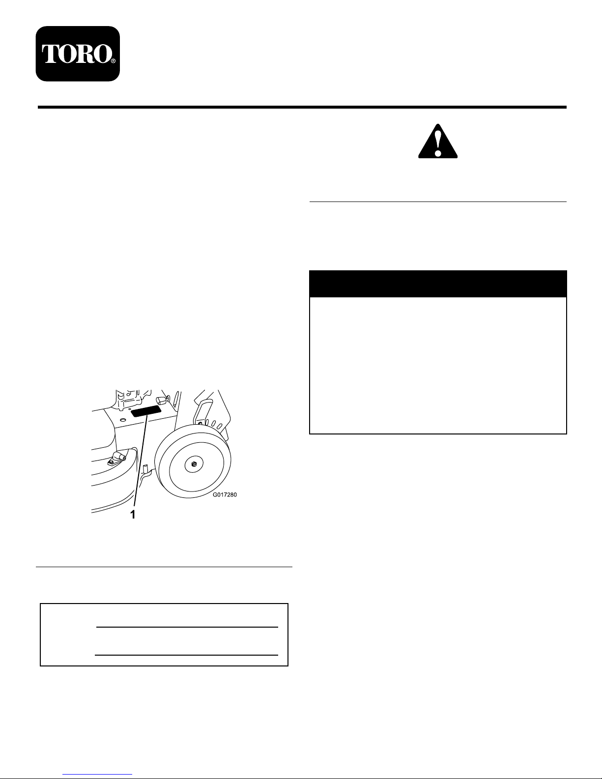
SafetyandInstructionalDecals.................................4
Setup............................................................................5
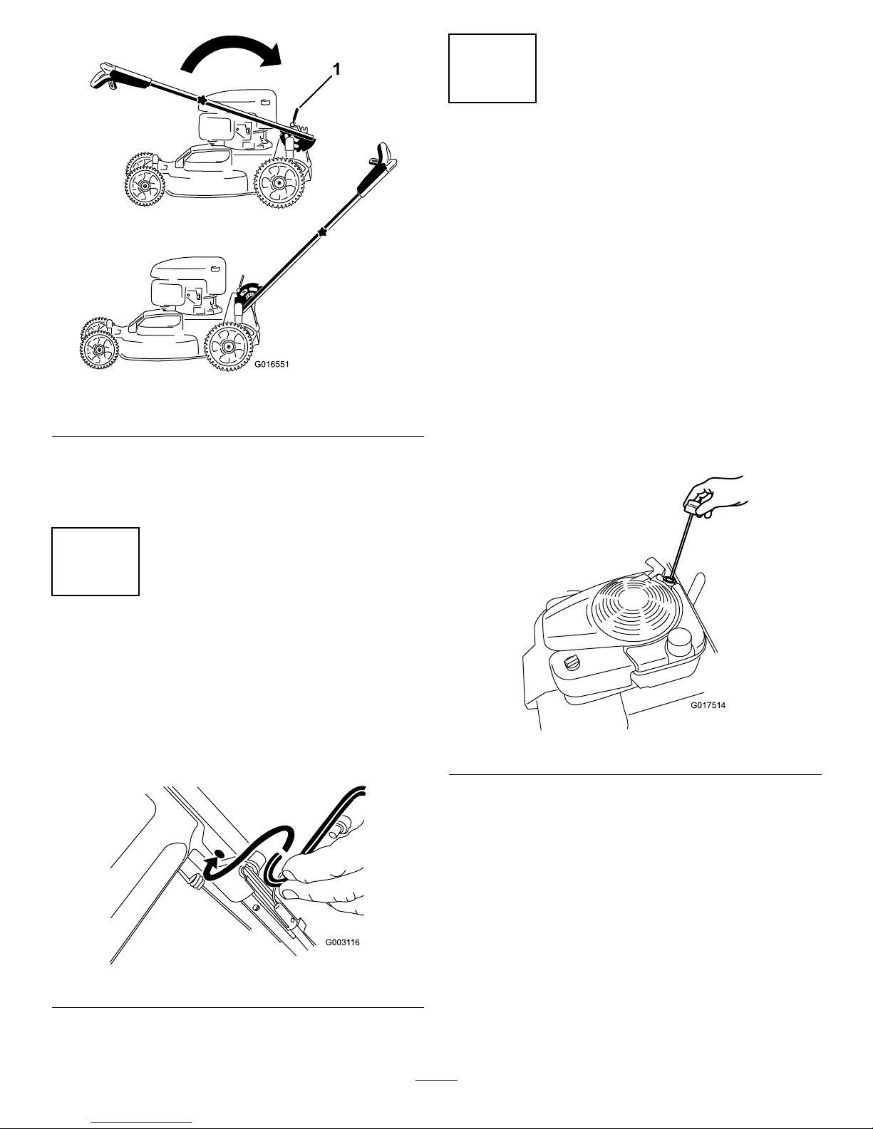
1AssemblingtheHandle..........................................5
2InstallingtheBlade-ControlBar..............................6
3FillingtheEnginewithOil......................................6
4ChargingtheBattery..............................................7
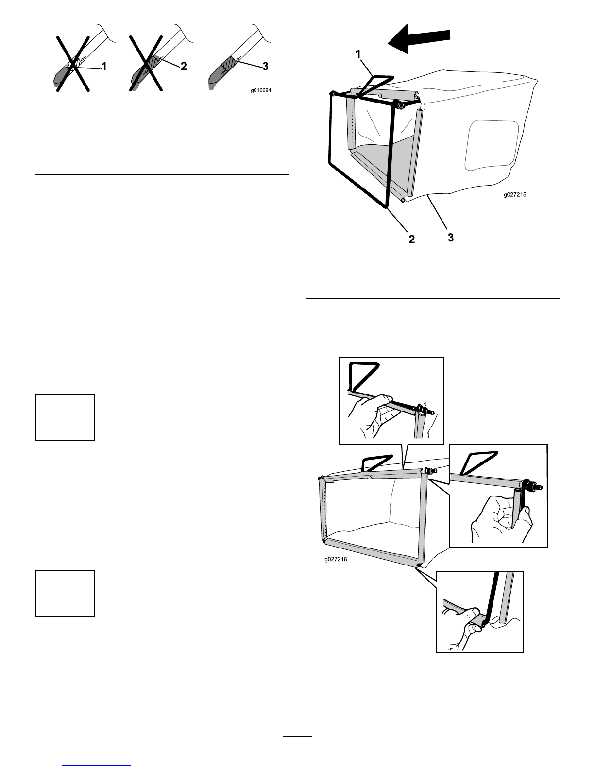
5AssemblingtheGrassBag......................................7
ProductOverview..........................................................8
Operation.....................................................................9
FillingtheFuelTank................................................9
CheckingtheEngine-OilLevel..................................9
AdjustingtheCuttingHeight....................................10
AdjustingtheHandleHeight....................................11
StartingtheEngine.................................................11
UsingtheSelf-PropelDrive.....................................11
StoppingtheEngine...............................................12
EngagingtheBlade.................................................12
DisengagingtheBlade.............................................12
CheckingtheBlade-StopSystemOperation................13
RecyclingtheClippings...........................................13
BaggingtheClippings.............................................13
Side-DischargingtheClippings.................................14
OperatingTips......................................................15
Maintenance.................................................................16
RecommendedMaintenanceSchedule(s)......................16
PreparingforMaintenance.......................................16
ServicingtheAirFilter............................................17
ChangingtheEngineOil.........................................17
ChargingtheBattery...............................................18
ReplacingtheFuse..................................................18
ReplacingtheBattery..............................................18
AdjustingtheSelf-PropelDrive................................19
ServicingtheBlade-DriveSystem.............................20
ServicingtheCuttingBlades.....................................20
CheckingforBentBlades........................................21
RemovingtheBlades..............................................22
InstallingtheBlades................................................22
CleaningundertheMachine.....................................23
Storage........................................................................24
GeneralInformation...............................................24
PreparingtheFuelSystem.......................................24
PreparingtheEngine..............................................24
RemovingtheMachinefromStorage.........................24
Safety
ThislawnmowermeetsorexceedstheCPSCbladesafety
requirementsforwalk-behindrotarylawnmowersandthe
B71.1specicationsoftheAmericanNationalStandards
Instituteineffectatthetimeofproduction.
Readandunderstandthecontentsofthismanualbefore
youstarttheengine.
Thesafetyalertsymbol(Figure2)isusedtoalertyouto
potentialpersonalinjuryhazards.Obeyallsafetymessages
thatfollowthissymboltoavoidpossibleinjuryordeath.
Improperlyusingormaintainingthismowercouldresultin
injuryordeath.Toreducethispotential,complywiththe
followingsafetyinstructions.
Thefollowinginstructionshavebeenadaptedfromthe
ANSI/OPEIstandardB71.1-2012.
Thiscuttingmachinecanamputatehandsandfeetand
throwobjects.Failuretoobservethefollowingsafety
instructionscouldresultinseriousinjuryordeath.
GeneralOperation
•Read,understand,andfollowallinstructionsonthe
machineandinthemanual(s)beforestartingtheengine.
•Donotputhandsorfeetnearorunderthemachine.
Keepclearofthedischargeopeningatalltimes.
•Onlyallowresponsibleadultswhoarefamiliarwiththe
instructionstooperatethismachine.
•Cleartheareaofobjectssuchasrocks,wire,toys,etc.,
whichcouldbethrownbytheblade.Staybehindthe
handlewhentheengineisrunning.
•Besuretheareaisclearofbystandersbeforeoperating.
Stopmachineifanyoneentersthearea.
•Donotoperatethemachinebarefootedorwhilewearing
sandals.Alwayswearsubstantialfootwear.
•Donotpullthemachinebackwardunlessitisabsolutely
necessary.Alwayslookdownandbehindbeforeand
whilemovingbackwardwiththemachine.
•Neverdirectdischargedmaterialtowardanyone.Avoid
dischargingmaterialagainstawallorobstruction.
Materialmayricochetbacktowardyouorbystanders.
Stopthebladewhencrossinggravelsurfaces.
•Donotoperatethemachinewithouttheentiregrass
catcher,dischargeguard,rearguard,orothersafety
protectivedevicesinplaceandworking.
•Neverleavearunningmachineunattended.
•Stoptheengineandwaituntilthebladecomestoa
completestopbeforecleaningthemachine,removing
grasscatcher,oruncloggingthedischargeguard.
•Operatethemachineonlyindaylightorgoodarticial
light.
•Donotoperatethemachinewhileundertheinuence
ofalcoholordrugs.
2

•Neveroperatethemachineinwetgrass.Alwaysbesure
ofyourfooting;walk;neverrun.
•Disengagethedrivesystem,ifsoequipped,before
startingtheengine.
•Ifthemachineshouldstarttovibrateabnormally,stop
theengineandcheckforthecauseimmediately.Vibration
isgenerallyawarningoftrouble.
•Alwaysweareyeprotectionwhenoperatingthemachine.
•Seethemanufacturer'sinstructionsforproperoperation
andinstallationofaccessories.Useonlyaccessories
approvedbythemanufacturer.
SlopeOperation
Slopesareamajorfactorrelatedtoslipandfallaccidents,
whichcanresultinsevereinjury.Operationonallslopes
requiresextracaution.Ifyoufeeluneasyonaslope,donot
mowit.
•Mowacrossthefaceofslopes;neverupanddown.
Exerciseextremecautionwhenchangingdirectionon
slopes.
•Watchforholes,ruts,bumps,rocks,orotherhidden
objects.Uneventerraincouldcauseaslip-and-fall
accident.Tallgrasscanhideobstacles.
•Donotmowonwetgrassorexcessivelysteepslopes.
Poorfootingcouldcauseaslip-and-fallaccident.
•Donotmowneardrop-offs,ditches,orembankments.
Youcouldloseyourfootingorbalance.
Children
Tragicaccidentscanoccuriftheoperatorisnotalerttothe
presenceofchildren.Childrenareoftenattractedtothe
machineandthemowingactivity.Neverassumethatchildren
willremainwhereyoulastsawthem.
•Keepchildrenoutofthemowingareaandunderthe
watchfulcareofaresponsibleadultotherthanthe
operator.
•Bealertandturnthemachineoffifachildentersthearea.
•Neverallowchildrentooperatethemachine.
•Useextracarewhenapproachingblindcorners,shrubs,
trees,orotherobjectsthatmayblockyourviewofachild.
Service
SafeHandlingofGasoline
Toavoidpersonalinjuryorpropertydamage,use
extremecareinhandlinggasoline.Gasolineisextremely
ammableandthevaporsareexplosive.
•Extinguishallcigarettes,cigars,pipes,andothersources
ofignition.
•Useonlyanapprovedgasolinecontainer.
•Neverremovethefuelcaporaddfuelwiththeengine
running.Allowtheenginetocoolbeforerefueling.
•Neverrefuelthemachineindoors.
•Neverstorethemachineorfuelcontainerwherethereis
anopename,spark,orpilotlight,suchasonawater
heateroronotherappliances.
•Neverllcontainersinsideavehicleoronatruckor
trailerbedwithaplasticliner.Alwaysplacecontainerson
theground,awayfromyourvehiclebeforelling.
•Removegas-poweredequipmentfromthetruckortrailer
andrefuelitontheground.Ifthisisnotpossible,then
refuelsuchequipmentwithaportablecontainerrather
thanfromagasolinedispensernozzle.
•Keepthenozzleincontactwiththerimofthefueltank
orcontaineropeningatalltimesuntilfuelingiscomplete.
Donotuseanozzlelock-opendevice.
•Iffuelisspilledonclothing,changeclothingimmediately.
•Neveroverllthefueltank.Replacethefuelcapand
tightenitsecurely.
WARNING
Exhaustcontainscarbonmonoxide,anodorless,
deadlypoisonthatcankillyou.
Donotruntheengineindoorsorinanenclosed
area.
GeneralService
•Neveroperatethemachineinaclosedarea.
•Keepallnutsandboltstighttobesurethattheequipment
isinsafeworkingcondition.
•Nevertamperwithsafetydevices.Checktheirproper
operationregularly.
•Keepmachinefreeofgrass,leaves,orotherdebris
build-up.Cleanupoilorfuelspillageandremoveany
fuel-soakeddebris.Allowthemachinetocoolbefore
storingit.
•Ifyoustrikeaforeignobject,stopandinspectthe
machine.Repairthemachine,ifnecessary,beforestarting
it.
•Nevermakeanyadjustmentsorrepairswiththeengine
running.Disconnectthespark-plugwireandground
againsttheenginetopreventitfromunintentionally
starting.
•Checkthegrasscatchercomponentsandthedischarge
guardfrequentlyandreplacethemwiththemanufacturer's
recommendedpartswhennecessary.
•Mowerbladesaresharp.Wrapthebladeorweargloves,
anduseextracautionwhenservicingthem.
•Donotchangetheenginegovernorsettingoroverspeed
theengine.
3

•Maintainorreplacesafetyandinstructionlabelsas
necessary.
•Tobestprotectyourinvestmentandmaintainoptimal
performanceofyourToroequipment,countonToro
genuineparts.Whenitcomestoreliability,Torodelivers
replacementpartsdesignedtotheexactengineering
specicationsofourequipment.Forpeaceofmind,insist
onTorogenuineparts.
SafetyandInstructionalDecals
Important:Safetyandinstructiondecalsarelocatednearareasofpotentialdanger.Replacedamageddecals.
Manufacturer'sMark
1.Indicatesthebladeisidentiedasapartfromtheoriginal
machinemanufacturer.
94-8072
104-7953
Electric-startmodelonly
1.Warning—readtheOperator'sManualforinformationonchargingthebattery;containslead;donotdiscard.
2.ReadtheOperator'sManual.
108-8117
108-9751
Electric-startmodelonly
1.Engine—stop3.Engine—start
2.Engine—run
117-2718
120-9570
1.Warning—stayawayfrommovingparts,keepallguards
andshieldsinplace.
4

131-0894
TractionAdjustment
1.Attention;readtheOperator'sManual—1)Loosenthe
knobbyturningitcounterclockwise;2)Pullthecable(s)
awayfromtheenginetodecreasethetraction,orpush
thecable(s)towardtheenginetoincreasethetraction;3)
Tightentheknobbyturningitclockwise.
131–4514
1.Warning—readtheOperator'sManual.
2.Cutting/dismembermenthazardofhandorfoot,mower
blade—stayawayfrommovingparts;keepallguardsand
shieldsinplace.
3.Cutting/dismembermenthazardofhandorfoot,mower
blade—disconnectthespark-plugwireandreadthe
instructionsbeforeservicingorperformingmaintenance.
4.Thrownobjecthazard—keepbystandersasafedistance
fromthemachine;stoptheenginebeforeleavingthe
operatingposition;pickupanydebrisbeforemowing.
5.Cutting/dismembermenthazardofhandorfoot,mower
blade—donotoperateupanddownslopes;operatesideto
sideonslopes;lookbehindyouwhenbackingup.
Setup
Important:Removeanddiscardtheprotectiveplastic
sheetthatcoverstheengine.
1
AssemblingtheHandle
NoPartsRequired
Procedure
WARNING
Assemblingandunfoldingthehandleimproperly
candamagethecables,causinganunsafeoperating
condition.
•Donotdamagethecableswhenunfoldingthe
handle.
•Ifacableisdamaged,contactanAuthorized
ServiceDealer.
1.Rotatetheupperhandlesothatitneststogetherwith
thelowerhandle(Figure3),andtightenbothknobson
thehandletolocktheupperhandleinplace(Figure4).
1
G016547
2
Figure3
1.Upperhandle2.Knob(2)
5

1
G016551
Figure4
1.Handle-locklever
2.Releasethehandle-locklever(Figure4).
3.Pullthehandlerearwardandlockitintoposition
(Figure4).
2
InstallingtheBlade-Control
Bar
NoPartsRequired
Procedure
Installtheblade-controlbarintotheupperhandle(Figure5).
Figure5
3
FillingtheEnginewithOil
NoPartsRequired
Procedure
Important:Yourmachine
does not
comewithoilin
theengine.Beforestartingtheengine,lltheengine
withoil.
Max.ll:0.59L(20oz),type:SAE30detergentoilwithan
APIserviceclassicationofSF,SG,SH,SJ,SL,orhigher.
Note:Whenthecrankcaseisempty,pourabout3/4of
thecrankcasecapacityofoilinthecrankcase,thendothe
following:
1.Movethemachinetoalevelsurface.
2.Removethedipstickbyrotatingthecap
counterclockwiseandpullingitout(Figure6).
G017514
Figure6
3.Wipethedipstickcleanwithacleancloth.
4.Insertthedipstickfullyintotheoil-lltube,then
removethedipstick.
5.Readtheoillevelonthedipstick(Figure6).
6

Figure7
1.Theoillevelistoolow;
addoiltothecrankcase.
3.Theoilleveliscorrect.
2.Theoillevelistoohigh;
removeoilfromthe
crankcase.
•Iftheoillevelistoolow,slowlypourasmall
amountofoilintotheoil-lltube,wait3minutes,
andrepeatsteps3through5untiltheoillevelon
thedipstickiscorrectasshowninFigure7.
•Iftheoillevelistoohigh,draintheexcessoiluntil
youobtainthecorrectoillevelonthedipstick.To
draintheexcessoil,refertoChangingtheEngine
Oil(page17).
Important:Iftheoillevelinthecrankcaseistoo
lowortoohighandyouruntheengine,youmay
damagetheengine.
6.Installthedipsticksecurely.
Important:
Change the engine oil after the r st 5
operating hour s
;changeityearlythereafter.Refer
toChangingtheEngineOil(page17).
4
ChargingtheBattery
NoPartsRequired
Procedure
Electric-startmodelonly
RefertoChargingtheBattery(page18).
5
AssemblingtheGrassBag
NoPartsRequired
Procedure
1.SlipthegrassbagovertheframeasshowninFigure8.
1
23
g027215
Figure8
1.Handle3.Grassbag
2.Frame
Note:Donotslipthebagoverthehandle(Figure8).
2.Hookthebottomchannelofthebagontothebottom
oftheframe(Figure9).
g027216
Figure9
3.Hookthetopandsidechannelsofthebagontothetop
andsidesoftheframe,respectively(Figure9).
7

ProductOverview
2
14
113
3
4
5
67
8
9
10
11
12
g027390
15
16
17
Figure10
1.Side-dischargedeector10.Ignitionswitch
(electric-startmodelonly)
ortoggleswitch(standard
modelonly)
2.Sparkplug11.Battery(electric-start
modelonly;notshown)
3.Oilll/dipstick(notshown)12.Rearcutting-heightlever
4.Recoil-starthandle13.Rear-dischargedeector
5.Fuel-tankcap14.Fuse
6.Handle-locklever15.Airlter
7.Handleknob(2)16.Washoutport
8.Adjustmentknobforthe
self-propeldrive
17.Frontcutting-heightlever
9.Upperhandle
2
1
3
4
5
g027394
Figure11
Upperhandle
1.Adjustmentknobforthe
self-propeldrive
4.Blade-controlbar
2.Traction-assisthandle5.Ignitionswitch
(electric-startmodelonly)
ortoggleswitch(standard
modelonly)
3.Blade-control-barlock
g017219
1
2
34
Figure12
1.Grassbag3.Side-dischargechute
2.Rear-dischargeplug
(installed)
4.Batterycharger
(electric-startmodelonly)
8

Operation
FillingtheFuelTank
DANGER
Gasolineisextremelyammableandexplosive.A
reorexplosionfromgasolinecanburnyouand
others.
•Topreventastaticchargefromignitingthe
gasoline,placethecontainerand/ormachine
directlyonthegroundbeforelling,notina
vehicleoronanobject.
•Fillthetankoutdoorswhentheengineiscold.
Wipeupspills.
•Donothandlegasolinewhensmokingoraround
anopenameorsparks.
•Storegasolineinanapprovedfuelcontainer,out
ofthereachofchildren.
•Forbestresults,useonlyclean,fresh,unleadedgasoline
withanoctaneratingof87orhigher((R+M)/2rating
method).
•Oxygenatedfuelwithupto10%ethanolor15%MTBE
byvolumeisacceptable.
•Donotuseethanolblendsofgasoline,suchasE15
orE85,withmorethan10%ethanolbyvolume.
Performanceproblemsand/orenginedamagemayresult,
whichmaynotbecoveredunderwarranty.
•Donotusegasolinecontainingmethanol.
•Donotstorefueleitherinthefueltankorinfuel
containersoverthewinterunlessfuelstabilizerhasbeen
addedtothefuel.
•Donotaddoiltogasoline.
Important:Toreducestartingproblems,addfuel
stabilizertothefuelallseason,mixingitwithgasoline
lessthan30daysold.
1.Cleanaroundthefuel-tankcap,andremovethecap
fromthetank(Figure13).
6 mm (1/4 inch)
G027619
Figure13
2.Fillthefueltank,leavingatleast6mm(1/4inch)from
thebottomoftheneckemptytoallowthegasoline
roomtoexpand(Figure13).
3.Installthefuel-tankcapandtightenitsecurelybyhand.
CheckingtheEngine-OilLevel
ServiceInterval:Beforeeachuseordaily
Note:Max.ll:0.59L(20oz),type:SAE30detergent
oilwithanAPIserviceclassicationofSF,SG,SH,SJ,SL,
orhigher.
1.Movethemachinetoalevelsurface.
2.Removethedipstick(Figure14).
G017514
Figure14
3.Wipethedipstickcleanwithacleancloth.
4.Insertthedipstickfullyintotheoil-lltube,then
removethedipstick.
5.Readtheoillevelonthedipstick(Figure15).
9

Figure15
1.Theoillevelistoolow;
addoiltothecrankcase.
3.Theoilleveliscorrect.
2.Theoillevelistoohigh;
removeoilfromthe
crankcase.
•Iftheoillevelistoolow,slowlypourasmall
amountofoilintotheoil-lltube,wait3minutes,
andrepeatsteps3through5untiltheoillevelis
correctasshowninFigure15.
•Iftheoillevelistoohigh,draintheexcessoiluntil
youobtainthecorrectoillevelonthedipstick.To
draintheexcessoil,refertoChangingtheEngine
Oil(page17).
Important:Iftheoillevelinthecrankcaseistoo
lowortoohighandyouruntheengine,youmay
damagetheengine.
6.Installthedipsticksecurely.
AdjustingtheCuttingHeight
WARNING
Adjustingthecuttingheightmaybringyouinto
contactwiththemovingblade,causingserious
injury.
•Stoptheengineandwaitforallmovingparts
tostop.
•Donotputyourngersunderthehousingwhen
adjustingthecuttingheight.
Adjustthecuttingheightasdesired;refertoFigure14and
Figure15.
Note:Toraisethemachine,movethefrontandrear
cutting-heightleversforward;tolowerthemachine,movethe
cutting-heightleversrearward.Setthefrontandrearwheels
tothesameheightunlessspecialcircumstancesrequire
otherwise;refertoOperatingTips(page15).
12345
6
7
G017634
Figure16
Frontcutting-heightlever
1.A:10.8cm(4-1/4inches)5.E:5.7cm(2-1/4inches)
2.B:9.5cm(3-3/4inches)6.F:4.4cm(1-3/4inches)
3.C:8.3cm(3-1/4inches)7.G:3.2cm(1-1/4inches)
4.D:7.0cm(2-3/4inches)
1
2345
6
7
G017635
Figure17
Rearcutting-heightlever
1.A:10.8cm(4-1/4inches)5.E:5.7cm(2-1/4inches)
2.B:9.5cm(3-3/4inches)6.F:4.4cm(1-3/4inches)
3.C:8.3cm(3-1/4inches)7.G:3.2cm(1-1/4inches)
4.D:7.0cm(2-3/4inches)
10

AdjustingtheHandleHeight
Youcanraiseorlowerthehandletoapositionmore
comfortableforyou.
1.Liftthehandleslightlyandpullthehandle-locklever
rearwardtodisengagethehandle-lockpins(Figure18).
2
G016488
3
1
Figure18
1.Handle-locklever3.Notches
2.Handle-lockpin(2)
2.Rotatethehandleandalignthedesirednotchinthe
handlebrackettothehandle-lockpins;refertoFigure
18.
3.Releasethehandle-locklevertosecurethehandlein
place.
StartingtheEngine
StandardModel
Pulltherecoilhandleslowlyuntilyoufeelresistance,thenpull
itsharply.Allowtheropetoreturntotheengineslowly.
Note:Ifthemachinedoesnotstartafterseveralattempts,
contactanAuthorizedServiceDealer.
Electric-startModel
Youcanstarttheengineonanelectric-startmodelbyusing
eithertheignitionkeyortherecoil-starthandle.
•IgnitionKey:
TurnandholdtheignitionkeytotheStartposition
(Figure19);whentheenginestarts,releasethekey.
Important:Donotattempttostarttheenginewith
theblade-controlbarengaged;otherwise,youmay
blowthefuse.
Note:DonotholdtheignitionkeyintheStartposition
forlongerthan5secondstopreventburningoutthe
startermotor.
G017516
Figure19
•Recoil-StartHandle:
1.TurntheignitionkeytotheRunposition(Figure
19).
2.Pulltherecoilhandleslowlytotherearuntilyou
feelresistance,thenpullsharply.Allowtheropeto
returntotheengineslowly.
UsingtheSelf-PropelDrive
Tooperatetheself-propeldrive,simplywalkwithyourhands
ontheupperhandleandyourelbowsatyoursides,andthe
machinewillautomaticallykeeppacewithyou(Figure20).
Note:Youcanself-propelthemachinewiththeblades
engagedordisengaged.
G017595
Figure20
Note:Usethetraction-assisthandleinsituationswhenyou
needmorecontrolthanyouhavewiththeself-propeldrive
alone.
11

StoppingtheEngine
StandardModel
Pressthetoggleswitch(Figure21)totheStoppositionand
holdituntiltheenginestops.
G017636
Figure21
1.Toggleswitch
Electric-startModel
1.TurnthekeytotheOffposition(Figure22).
G017517
Figure22
2.Whentheenginestops,removetheignitionkeyand
takeitwithyouwhenyouleavethemachine.
EngagingtheBlade
Whenyoustartyourengine,thebladedoesnotturn.You
mustengagethebladetomow.
1.Pulltheblade-control-barlockbacktotheblade-control
bar(Figure23).
g016484
1
2
Figure23
1.Blade-controlbarlock2.Blade-controlbar
2.Slowlypulltheblade-controlbarbacktothehandle
(Figure23).
3.Holdtheblade-controlbaragainstthehandle(Figure
24).
g016485
Figure24
DisengagingtheBlade
Releasetheblade-controlbar(Figure25).
Figure25
Important:Whenyoureleasetheblade-controlbar,
thebladeshouldstopwithin3seconds.Ifitdoesnot
stopproperly,stopusingyourmachineimmediatelyand
contactanAuthorizedServiceDealer.
12

CheckingtheBlade-Stop
SystemOperation
ServiceInterval:Beforeeachuseordaily
Checkthatthebladesstopwithin3secondsofreleasingthe
blade-controlbar.
UsingtheGrassBag
Youcanusethegrassbagtochecktheblade-stopsystem.
1.Removetherear-dischargeplug.
2.Installtheemptygrassbagonthemachine.
3.Starttheengine.
4.Engagetheblade.
Note:Thebagshouldbegintoinate,indicatingthat
thebladesarerotating.
5.Whilewatchingthebag,releasetheblade-controlbar.
Note:Ifthebagdoesnotdeatewithin3secondsof
releasingtheblade-controlbar,theblade-stopsystem
maybedeterioratingand,ifignored,couldresultin
anunsafeoperatingcondition.Havethemachine
inspectedandservicedbyanAuthorizedService
Dealer.
6.Stoptheengineandwaitforallmovingpartstostop.
NotUsingtheGrassBag
1.Movethemachineontoapavedsurfaceinanon-windy
area.
2.Setall4wheelstothe89mm(3-1/2inch)cutting
heightsetting.
3.Takeahalfsheetofnewspaperandcrumpleitintoa
ballsmallenoughtogounderthemachinehousing
(about76mm(3inches)indiameter).
4.Placethenewspaperballabout13cm(5inches)in
frontofthemachine.
5.Starttheengine.
6.Engagetheblade.
7.Releasetheblade-controlbarandbegincountingout3
seconds.
8.Onthecountof3,pushthemachinequicklyforward
overthenewspaper.
9.Stoptheengineandwaitforallmovingpartstostop.
10.Gotothefrontofthemachineandcheckthe
newspaperball.
Note:Ifthenewspaperballdidnotgounderthe
machine,repeatsteps4through10.
11.Ifthenewspaperisunravelledorshredded,theblades
didnotstopproperly,whichcouldresultinanunsafe
operatingcondition.ContactanAuthorizedService
Dealer.
RecyclingtheClippings
Thismachinecomesfromthefactoryreadytorecyclegrass
andleafclippingsbackintothelawn.Topreparethemachine
torecycle,dothefollowing:
•Iftheside-dischargechuteisonthemachine,removeit
andlowertheside-dischargedeector;refertoRemoving
theSide-DischargeChute(page15).
•Ifthegrassbagisonthemachine,removeit;referto
RemovingtheGrassBag(page14).
•Iftherear-dischargeplugisnotinstalled,gripitbythe
handle,raisethereardeector,andinsertitintothe
rear-dischargechuteuntilthelatchlocksintoplace;refer
toFigure26.
1
2
G016490
3
Figure26
1.Reardeector3.Therear-dischargeplug
installed
2.Inserttherear-discharge
plug
WARNING
Ensurethattherear-dischargeplugisinplace
beforeyourecycletheclippings.Neverengagethe
bladeswithouteithertherear-dischargeplugorthe
grassbaginstalled.
BaggingtheClippings
Usethegrassbagwhenyouwanttocollectgrassandleaf
clippingsfromthelawn.
WARNING
Aworngrassbagcouldallowsmallstonesand
othersimilardebristobethrowntowardyouor
bystanders,resultinginseriouspersonalinjuryor
death.
Checkthegrassbagfrequently.Ifitisdamaged,
installanewTororeplacementbag.
13

Iftheside-dischargechuteisonthemower,removeitbefore
baggingtheclippings;refertoRemovingtheSide-Discharge
Chute(page15).
InstallingtheGrassBag
1.Raiseandholdupthereardeector(Figure27).
1
2
G017408
3
Figure27
1.Reardeector3.Latch
2.Rear-dischargeplug
2.Removetherear-dischargeplugbypullingdownonthe
latchwithyourthumbandpullingtheplugoutfrom
themachine(Figure27).
3.Installthebagrodintothenotchesatthebaseofthe
handleandrockthebagbackandforthtoensurethat
therodisseatedatthebottomofbothnotches;refer
toFigure28.
G016513
12
Figure28
1.Bagrod2.Notch(2)
4.Lowerthereardeectoruntilitrestsonthegrassbag.
RemovingtheGrassBag
Toremovethebag,reversethestepsinInstallingtheGrass
Bag(page14).
Side-Dischargingthe
Clippings
Usethesidedischargeforcuttingverytallgrass.
Ifthebagisonthemachine,removeitandinsertthe
rear-dischargeplug;refertoRemovingtheGrassBag(page
14)beforeside-dischargingtheclippings.
Important:Ensurethattherear-dischargeplugisin
placebeforeyourecycletheclippings(Figure26).
WARNING
Thebladeissharp;contactingthebladecanresult
inseriouspersonalinjury.
Stoptheengineandwaitforallmovingpartstostop
beforeleavingtheoperatingposition.
InstallingtheSide-DischargeChute
1.Liftopentheside-dischargedeector(Figure29).
G017521
1
2
Figure29
1.Side-dischargedeector2.Side-dischargechute
2.Installtheside-dischargechuteasshowninFigure29
andFigure30,andclosethedeectorontothechute.
14

G017522
Figure30
RemovingtheSide-DischargeChute
Toremovetheside-dischargechute,reversethestepsin
InstallingtheSide-DischargeChute(page14).
OperatingTips
GeneralMowingTips
•Cleartheareaofsticks,stones,wire,branches,andother
debristhatthebladecouldhit.
•Avoidstrikingsolidobjectswiththeblade.Never
deliberatelymowoveranyobject.
•Ifthemachinestrikesanobjectorstartstovibrate,
immediatelystoptheengine,disconnectthewirefrom
thesparkplug,andexaminethemachinefordamage.
•Forbestperformance,installanewbladebeforethe
cuttingseasonbegins.
•ReplacethebladewhennecessarywithaToro
replacementblade.
CuttingGrass
•Cutonlyaboutathirdofthegrassbladeatatime.Donot
cutbelowthe51mm(2-inch)settingunlessthegrassis
sparseoritislatefallwhengrassgrowthbeginstoslow
down.RefertoAdjustingtheCuttingHeight(page10).
•Whencuttinggrassover15cm(6inches)tall,mowatthe
highestcuttingheightsettingandwalkslower;thenmow
againatalowersettingforthebestlawnappearance.If
thegrassistoolong,themachinemayplugandcause
theenginetostall.
•Mowonlydrygrassorleaves.Wetgrassandleavestend
toclumpontheyardandcancausethemachinetoplug
ortheenginetostall.
WARNING
Wetgrassorleavescancauseseriousinjuryif
youslipandcontacttheblade.Mowonlyindry
conditions.
•Beawareofapotentialrehazardinverydryconditions,
followalllocalrewarnings,andkeepthemachinefree
ofdrygrassandleafdebris.
•Alternatethemowingdirection.Thishelpsdispersethe
clippingsoverthelawnforevenfertilization.
•Ifthenishedlawnappearanceisunsatisfactory,try1
ormoreofthefollowing:
–Replacethebladeorhaveitsharpened.
–Walkataslowerpacewhilemowing.
–Raisethecuttingheightonyourmachine.
–Cutthegrassmorefrequently.
–Overlapcuttingswathsinsteadofcuttingafullswath
witheachpass.
–Setthecuttingheightonthefrontwheelsonenotch
lowerthantherearwheels.Forexample,setthefront
wheelsat51mm(2-inches)andtherearwheelsat64
mm(2-1/2inches).
CuttingLeaves
•Aftercuttingthelawn,ensurethathalfofthelawnshows
throughthecutleafcover.Youmayneedtomakemore
thanasinglepassovertheleaves.
•Iftherearemorethan13cm(5inches)ofleavesonthe
lawn,setthefrontcuttingheight1or2notcheshigher
thantherearcuttingheight.
•Slowdownyourmowingspeedifthemachinedoesnot
cuttheleavesnelyenough.
15

Maintenance
Note:Determinetheleftandrightsidesofthemachinefromthenormaloperatingposition.
RecommendedMaintenanceSchedule(s)
MaintenanceService
IntervalMaintenanceProcedure
Aftertherst5hours•Changetheengineoil.
Beforeeachuseordaily
•Checktheengine-oillevel.
•Checktheblade-brake-clutchoperation.
•Checktheaircleanerandcleanorreplaceit,ifnecessary.
•Checkthecuttingblades.
•Cleangrassclippingsanddirtfromunderthemachine.
Every25hours•Chargethebattery(electric-startmodelonly).
Every50hours•Changetheengineoil.
•Servicetheblade-drivesystem.
Yearly
•Servicetheairlter;replaceitmorefrequentlyindustyoperatingconditions.
•Changetheengineoil.
•Servicethecuttingblades.
•Refertoyourengineoperator'smanualforanyadditionalyearlymaintenance
procedures.
Yearlyorbeforestorage•Chargethebattery(electric-startmodelonly).
•Emptythefueltankbeforerepairsasdirectedandbeforeyearlystorage.
Important:Refertoyourengineowner'smanualforadditionalmaintenanceprocedures.
PreparingforMaintenance
1.Stoptheengineandwaitforallmovingpartstostop.
2.Disconnectthespark-plugwirefromthesparkplug
(Figure31).
G017520
1
Figure31
1.Spark-plugwire
3.Afterperformingthemaintenanceprocedure(s),
connectthespark-plugwiretothesparkplug.
Important:Beforetippingthemachinetochange
theoilorreplacetheblade,allowthefueltankto
rundrythroughnormalusage.Ifyoumusttip
themachinepriortorunningoutoffuel,usea
handfuelpumptoremovethefuel.Alwaystipthe
machineontoitsside,withthedipstickdown.
WARNING
Tippingthemachinemaycausethefueltoleak.
Gasolineisammableandexplosiveandcancause
personalinjury.
Runtheenginedryorremovethegasolinewitha
handpump;neversiphon.
16

ServicingtheAirFilter
ServiceInterval:Beforeeachuseordaily
Yearly
1.Loosenthefastenerandremovetheair-ltercover
(Figure32).
G017216
2
1
3
4
Figure32
1.Cover3.Filter
2.Fastener4.Base
2.Removeandinspectthelter.
•Ifthelterisdamagedoriswetwithoilorfuel,
replaceit.
•Ifthelterisdirty,tapitonahardsurfaceseveral
timesorblowthedebrisoutwardfromtheinterior
ofthelterusingcompressedairatlessthan207
kPa(30psi).
Note:Donotbrushorblowdirtfromtheoutside
ofthelter;eitherforcesdirtintothebers.
3.Cleantheair-lterbodyandcoverusingadamprag.
Keepdirtawayfromtheairopening.
4.Installthelterontothebase.
5.Installthecoverandscrewthefastenerdownsecurely.
ChangingtheEngineOil
ServiceInterval:Aftertherst5hours
Every50hours
Yearly
Note:Runtheengineafewminutesbeforechangingthe
oiltowarmit.Warmoilowsbetterandcarriesmore
contaminants.
1.Ensurethatthefueltankcontainslittleornofuelso
thatfueldoesnotleakoutwhenyoutipthemachine
ontoitsside.
2.Movethemachinetoalevelsurface.
3.Disconnectthewirefromthesparkplug.Referto
PreparingforMaintenance(page16).
4.Tipthemachineontoitsside,withthedipstickdown,
untiltheupperhandlerestsontheground.
5.Setanoil-drainpanunderthedipstick.
6.Removethedipstickanddraintheusedoilintothe
oil-drainpan(Figure33).
G017281
Figure33
7.Afterdrainingtheusedoil,returnthemachinetothe
operatingposition.
8.Pourabout3/4ofthecrankcasecapacityofoilinthe
crankcase.
Note:Max.ll:0.59L(20oz),type:SAE30
detergentoilwithanAPIserviceclassicationofSF,
SG,SH,SJ,SL,orhigher.
9.Waitabout3minutesfortheoiltosettleinthe
crankcase.
10.Wipethedipstickcleanwithacleancloth.
11.Insertthedipstickfullyintotheoil-lltube,then
removethedipstick.
12.Readtheoillevelonthedipstick(Figure34).
Figure34
1.Theoillevelistoolow;
addoiltothecrankcase.
3.Theoilleveliscorrect.
2.Theoillevelistoohigh;
removeoilfromthe
crankcase.
•Iftheoillevelistoolow,slowlypourasmall
amountofoilintotheoil-lltube,wait3minutes,
andrepeatsteps10through12untiltheoillevelis
correctasshowninFigure34.
•Iftheoillevelistoohigh,draintheexcessoiluntil
youobtainthecorrectoillevelonthedipstick.
17

Important:Iftheoillevelinthecrankcaseistoo
lowortoohighandyouruntheengine,youmay
damagetheengine.
13.Installthedipsticksecurely.
14.Recycletheusedoilproperly.
ChargingtheBattery
ServiceInterval:Every25hours
Yearlyorbeforestorage
Electric-startmodelonly
WARNING
Batteryposts,terminals,andrelatedaccessories
containleadandleadcompounds,chemicals
knowntotheStateofCaliforniatocausecancerand
reproductiveharm.
W ash y our hands after handling
the batter y .
Chargethebatteryfor24hoursinitially,thenmonthly(every
25starts)orasneeded.Alwaysusethechargerinasheltered
area,andchargethebatteryatroomtemperature(about22°
C,or70°F)wheneverpossible.
Note:Themachineisequippedwithanalternatorcharging
system.
1.Connectthechargertothewireharness,whichis
locatedbelowtheignitionkey(Figure35).
G017518
Figure35
2.Plugthechargerintoawalloutlet.
Note:Yourbatterychargermayhavea2-colorLED
displaythatindicatesthefollowingstatesofcharging:
•Aredlightindicatesthatthechargerischarging
thebattery.
•Agreenlightindicatesthatthechargerisfully
chargedorisdisconnectedfromthebattery.
•Aashinglightthatalternatesbetweenredand
greenindicatesthatthebatteryisnearlyfully
charged.Thisstatelastsonlyafewminutesuntil
thebatteryisfullycharged.
Note:Whenthebatterynolongerholdsacharge,
recyclethelead-acidbatteryaccordingtolocalcodes.
ReplacingtheFuse
Electric-startmodelonly
Ifthebatterydoesnotchargeortheenginedoesnotturn
withtheelectricstarter,thefusemaybeblown;replaceitwith
a40-ampplug-intypefuse.
Important:Youcannotstartthemachinewiththe
electricstarterorchargethebatteryunlessaworking
fuseisinstalled.
1.Openthesealedfuseholderandreplacethefuse
(Figure36).
G020856
1
Figure36
1.Fuseholder
2.Closethecovertothefuseholder,andensurethatit
issealedtightly.
ReplacingtheBattery
Electric-startmodelonly
RemovingtheOldBattery
1.ContactanAuthorizedToroPartsDealertoobtaina
replacementbattery.
2.Removethebeltcover;refertostep1ofServicingthe
Blade-driveSystem(page20).
3.Removetherear-dischargeplug.
4.Movethehandletotheverticalposition.
5.Removethe4smallboltsthatholdtherear-deector
andhandle-lockleverassemblyinplace.
6.Foldthehandleallthewayforward.
7.Removetherear-deectorandhandle-locklever
assembly(Figure36).
18

G017523
1
Figure37
1.Rear-deectorandhandle-lockleverassembly
8.Removethecoverfromthebattery.
9.Disconnecttheleadsfromthebattery.
10.Removeandbatteryandrecycleit.
Note:Recyclethebatteryaccordingtoyourstateand
localregulations.
InstallingtheNewBattery
1.Cleanthebattery-holdingareaonthemachinehousing.
2.Setthenewbatteryinplaceonthemachinehousing.
3.Connecttheleadstothenewbattery.
Note:Ensurethatyouconnecttheblack(negative)
wiretothenegative(-)terminalandthered(positive)
wiretothepositive(+)terminal.
4.Installthecoverontothebattery.
Note:Ensurethatthecovertsproperlyoverthe
wiringharness.
5.Installtherear-deectorandhandle-lockleverassembly
ontothemachine.
6.Raisethehandletotheverticalposition.
7.Securetheshroudwiththe4smallboltsthatyou
removedinstep5ofRemovingtheOldBattery(page
18).
8.Installtherear-dischargeplug.
9.Returnthehandletotheoperatingposition.
AdjustingtheSelf-PropelDrive
Wheneveryouinstallanewself-propelcableorifthe
self-propeldriveisoutofadjustment,adjusttheself-propel
drive.
1.Turntheadjustmentknobcounterclockwisetoloosen
thecableadjustment(Figure38).
g027709
Figure38
1.Handle(leftside)3.Self-propel-drivecable
2.Adjustmentknob
2.Adjustthetensiononthecable(Figure38)bypullingit
backorpushingitforwardandholdingthatposition.
Note:Pushthecabletowardtheenginetoincrease
thetraction;pullthecableawayfromtheengineto
decreasethetraction.
3.Turntheadjustmentknobclockwisetotightenthe
cableadjustment.
Note:Tightentheknobrmlybyhand.
19

ServicingtheBlade-Drive
System
ServiceInterval:Every50hours
1.Removetheblade-drivesystemcover(Figure39).
G016491
1
2
Figure39
1.Bolts2.Cover
2.Brushorblowoutdebrisfromtheinsideoftheshield
andaroundalltheparts.
3.Holda0.25mm(0.010-inch)feelergauge,apieceof
paper,oranotecardagainstthewallandslideitdown
behindthebelttensionspring.
Note:Ifthereisavisiblegapbetweenthegaugeand
thespring,tightentheadjustingboltandthenutuntil
thepaperbarelyslidesfreelyinandoutofthegap
(Figure40).
g017221
2
1
34
5
6
Figure40
1.Belt-tensionspring4.Adjustingnut
2.Adjustingbolt5.Blade-drivebelt
3.Gap6.Wall
Important:Donotovertightentheadjustingbolt.
Thiscoulddamagetheblade-drivebelt.
4.Installtheblade-drivesystemcoverthatyoupreviously
removed.
ServicingtheCuttingBlades
ServiceInterval:Yearly
Important:
Y ou will need a torque wr ench to install the
blades pr oper l y .
Ifyoudonothaveatorquewrenchor
areuncomfortableperformingthisprocedure,contact
anAuthorizedServiceDealer.
Examinethebladesforsharpnessandanywearordamage
wheneveryourunoutofgasoline.Ifthebladeedgesare
dullornicked,havethemsharpenedorreplacetheblades.
Ifabladeisworn,bent,damagedorcracked,replaceit
immediatelywithagenuineTororeplacementblade.
DANGER
Awornordamagedbladecanbreak,andapiece
ofthebladecouldbethrowntowardtheoperator
orabystander,resultinginseriouspersonalinjury
ordeath.
•Inspectthebladesperiodicallyforwearor
damage.
•Replaceawornordamagedblade.
Note:Maintainsharpbladesthroughoutthecuttingseason,
becausesharpbladescutcleanlywithouttearingorshredding
thegrassblades.
PreparingtoServicetheCuttingBlades
1.Lockthehandleintheverticalposition(Figure41);
refertoAdjustingtheHandleHeight(page11).
1
G025927
Figure41
1.Handlelockedintheverticalposition
2.Tipthemachineontoitsside,withthedipstickdown,
untiltheupperhandlerestsontheground.
20
Other manuals for TimeMaster 20199
3
This manual suits for next models
1
Table of contents
Other Toro Lawn Mower manuals

Toro
Toro 70082 User manual

Toro
Toro GrandStand 74568TE User manual

Toro
Toro 30881 User manual

Toro
Toro Greensmaster TriFlex 3300 User manual

Toro
Toro 74279TE User manual

Toro
Toro 75501 User manual

Toro
Toro Super Recycler 20062 User manual

Toro
Toro Z Master Revolution Series User manual

Toro
Toro timecutter 19-52ZX User manual

Toro
Toro GrandStand 74583 User manual