Toro 500 EFI User manual

Side By Side Off Road Utility Vehicle
500 EFI & 700 EFI
LCE/Residential Products
Service Manual

FOREWORD
This Toro Service Manual contains service, maintenance, and troubleshooting information for the 2015 Toro UTV500/
UTV700. The complete manual is designed to aid service personnel in service-oriented applications.
This manual is divided into sections. Each section covers a specific vehicle component or system and, in addition to the
standard service procedures, includes disassembling, inspecting, and assembling instructions. When using this manual
as a guide, the technician should use discretion as to how much disassembly is needed to correct any given condition.
This service manual is designed primarily for use by a Toro USD (Unlisted Service Dealer). The procedures found in
this manual are of varying difficulty, and certain service procedures in this manual require one or more special tools to
be completed. The technician should use sound judgement when determining which procedures can be completed
based on their skill level and access to appropriate special tools.
All Toro publications and decals display the words Warning, Caution, Note, and At This Point to emphasize important
information. The symbol ! WARNING identifies personal safety-related information. Be sure to follow the
directive because it deals with the possibility of serious personal injury or even death. A CAUTION identifies
unsafe practices which may result in vehicle-related damage. Follow the directive because it deals with the possibility
of damaging part or parts of the vehicle. The symbol NOTE: identifies supplementary information worthy of partic-
ular attention. The symbol AT THIS POINT directs the technician to certain and specific procedures to pro-
mote efficiency and to improve clarity.
At the time of publication, all information, photographs, and illustrations were technically correct. Some photographs
used in this manual are used for clarity purposes only and are not designed to depict actual conditions. Because Toro-
Exmark constantly refines and improves its products, no retroactive obligation is incurred.
All materials and specifications are subject to change without notice.
Keep this manual accessible in the shop area for reference.
Product Service and
Warranty Department
Toro
© 2015 Toro April 2015
®™ Trademarks of Toro

1
Table of Contents
General Information ........................................................ 2
General Specifications.........................................................2
Torque Specifications ..........................................................3
Torque Conversions (ft-lb/N-m)............................................5
Gasoline - Oil - Lubricant.....................................................5
Genuine Parts......................................................................6
Special Tools........................................................................6
Preparation For Storage ......................................................6
Preparation After Storage....................................................6
Periodic Maintenance...................................................... 7
Periodic Maintenance Chart ................................................7
Lubrication Points ................................................................8
Air Inlet Pre-Filter.................................................................8
Air Filter ...............................................................................8
Valve/Tappet Clearance.......................................................9
Testing Engine Compression.............................................10
Spark Plug .........................................................................10
Muffler/Spark Arrester .......................................................10
Engine/Transmission Oil - Filter.........................................11
Front Differential - Rear Drive Lubricant ............................12
Driveshaft/Coupling ...........................................................13
Nuts/Bolts/Cap Screws......................................................13
Headlight/Taillight-Brakelight .............................................13
Shift Lever..........................................................................14
Hydraulic Brake System ....................................................15
Burnishing Brake Pads ......................................................16
Checking/Replacing V-Belt ................................................17
Steering/Frame/Controls............................................... 19
Steering Wheel ..................................................................19
Tie Rods ............................................................................19
Steering Assembly.............................................................20
Upper Steering Shaft .........................................................21
Intermediate Steering Shaft Assembly ..............................22
Steering Knuckles..............................................................23
Accelerator Pedal ..............................................................25
Shift Lever..........................................................................25
Shift Cable .........................................................................25
LCD Gauge........................................................................26
Checking/Adjusting Front Wheel Alignment.......................27
Front Bumper Assembly ....................................................28
Hood ..................................................................................28
Fenders..............................................................................29
Floor ..................................................................................29
Dashboard .........................................................................30
Belly Panel.........................................................................30
Exhaust System.................................................................31
Cargo Box..........................................................................31
Taillight Assembly ..............................................................32
Seat ...................................................................................32
Troubleshooting .................................................................33
Engine/Transmission .................................................... 34
Troubleshooting .................................................................35
Removing Engine/Transmission ........................................37
Servicing Engine (500) ......................................................40
Servicing Engine (700) ......................................................77
Installing Engine/Transmission ........................................115
Fuel/Lubrication/Cooling............................................ 118
Throttle Body................................................................... 118
Gas Tank .........................................................................119
Gas/Vent Hoses ..............................................................121
Oil Filter/Oil Pump ...........................................................121
Liquid Cooling System ....................................................122
Radiator........................................................................... 122
Thermostat ...................................................................... 123
Fan ..................................................................................123
Water Pump ....................................................................124
Troubleshooting ...............................................................125
Electrical System ........................................................ 126
Battery.............................................................................126
Accessory Receptacle/Connector ...................................126
Brakelight Switch.............................................................127
Engine Coolant Temperature (ECT) Sensor.................... 127
Fan Motor ........................................................................128
Power Distribution Module (PDM) ................................... 128
Ignition Coil .....................................................................128
EFI Sensors/Components ...............................................129
Speed Sensor .................................................................130
RPM Limiter ....................................................................131
Ignition Switch .................................................................131
Headlight Switch .............................................................131
Drive Select Switch .........................................................132
Reverse Override Switch.................................................132
Front Drive Actuator ........................................................132
Stator Coil .......................................................................133
Starter Motor ...................................................................134
Starter Relay ...................................................................134
Electronic Control Module (ECM).................................... 135
Fuel Pump/Fuel Level Sensor ......................................... 135
Regulator/Rectifier ..........................................................136
Headlights .......................................................................137
Taillight-Brakelight ...........................................................137
Ignition Timing ................................................................. 137
Tilt Sensor .......................................................................137
Throttle Position Sensor (TPS)........................................139
EFI Diagnostic System.................................................... 139
Troubleshooting ...............................................................144
Drive System ............................................................... 145
Front Drive Actuator ........................................................145
Front Differential ..............................................................146
Drive Axles ...................................................................... 157
Rear Gear Case ..............................................................160
Hub.................................................................................. 162
Hydraulic Brake Caliper...................................................164
Universal Joints ............................................................... 167
Troubleshooting Drive System......................................... 169
Troubleshooting Brake System........................................ 170
Suspension.................................................................. 171
Shock Absorbers ............................................................. 171
Front A-Arms ................................................................... 171
Rear A-Arms ................................................................... 174
Wheels and Tires ............................................................ 175
Troubleshooting ...............................................................176
2
General Information
NOTE: Some photographs and illustrations used in
this manual are used for clarity purposes only and
are not designed to depict actual conditions.
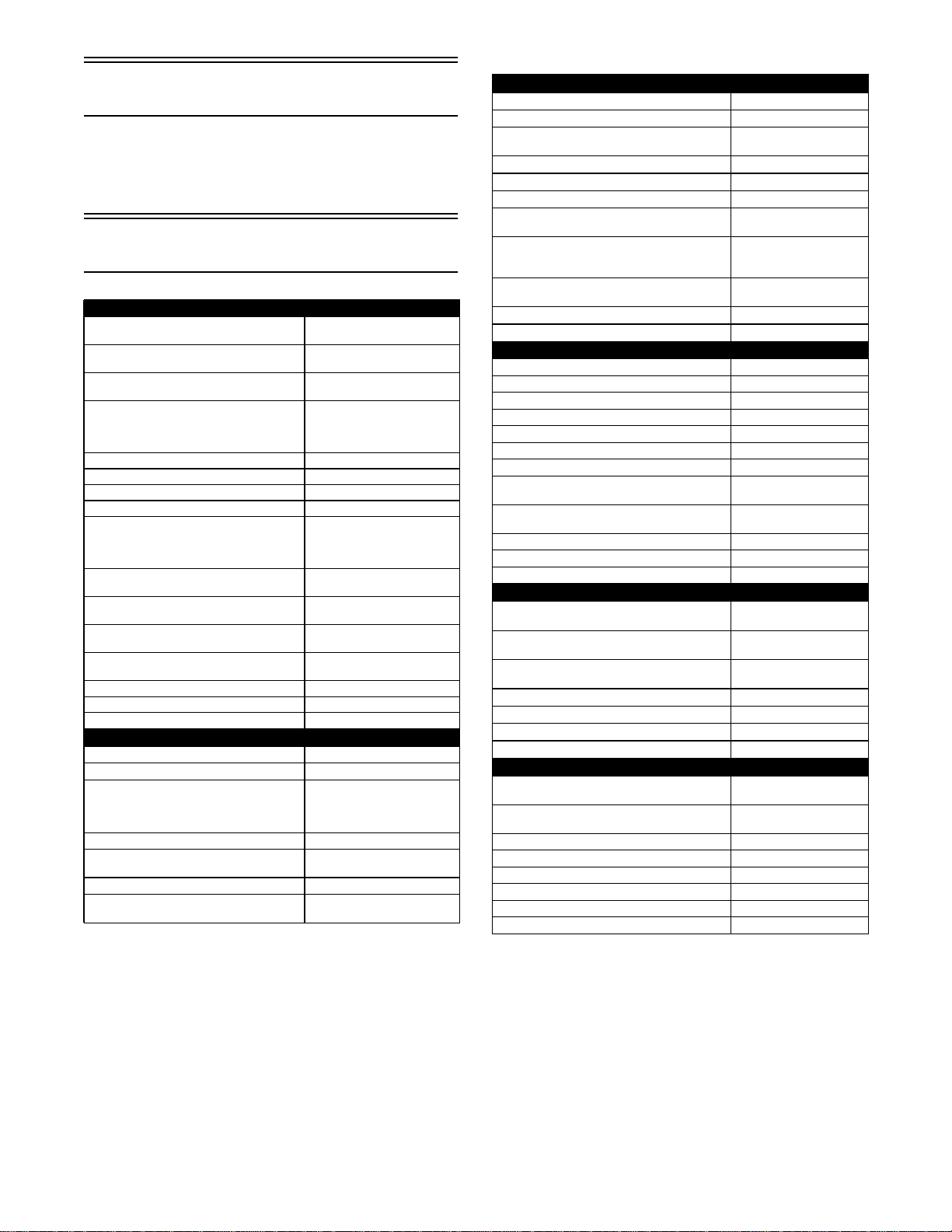
General Specifications
Specifications subject to change without notice.
MISCELLANY
Tire Size (front)
(rear)
26 x 10R-14
26 x 12R-14
Tire Inflation Pressure 1.12 kg/cm² (16 psi) - 500
1.41 kg/cm² (20 psi) - 700
Spark Plug Type NGK CR7E - 500
NGK CPR8E - 700
Spark Plug Gap 0.7-0.8 mm (0.028-0.031 in.)
-500
0.5-0.6 mm (0.019-0.024 in.)
- 700
Gas Tank Capacity 31 L (8.2 U.S. gal.)
Coolant Capacity 2.9 L (3.0 U.S. qt)
Front Differential Capacity 275 ml (9.3 fl oz)*
Rear Drive Capacity 250 ml (8.5 fl oz)*
Engine Oil Capacity (approx) (500)
(700)
3.3 L (3.5 U.S. qt) - Overhaul
2.8L(3.0U.S.qt)-Change
2.5 L (2.6 U.S. qt) - Overhaul
1.9 L (2.0 U.S. qt) - Change
Gasoline (recommended) 87 Octane Regular
Unleaded
Engine Oil (recommended) Toro ACX All Weather Syn-
thetic
Front Differential/Rear Drive Lubricant
(One inch below plug threads)
SAE Approved 80W-90 Hyp-
oid
Belt Width (minimum) 28.5 mm (1.12 in.) - 500
35.0 mm (1.38 in.) - 700
Brake Fluid DOT 4
Taillight/Brakelight 12V/8W/27W
Headlight 12V/27W (4)
ELECTRICAL SYSTEM
Ignition Timing 10° BTDC @ 1500 RPM
Spark Plug Cap 5000 ohms
Ignition Coil Resistance (primary)
(secondary)
Less than 5.0 ohms - 500
Less than 1 ohm - 700
12k-19k ohms - 500
1.8M ohms - 700
Ignition Coil Primary Voltage Battery Voltage
Stator Coil Resistance (CKP Sensor)
(AC generator)
104-156 ohms
Less than 1 ohm
AC Generator Output (no load) 60 AC volts @ 5000 RPM
Crankshaft Position Sensor AC Voltage 2.5 volts or more - 500
2.0 volts or more - 700
CYLINDER, PISTON, AND RINGS (500)
Piston Skirt/Cylinder Clearance 0.025-0.055 mm
Piston Diameter 8 mm from Skirt End 88.96-88.98 mm
Piston Ring Free End Gap (max) (1st)
(2nd)
11.6 mm
10.1 mm
Bore x Stroke 89.0 x 71.2 mm
Cylinder Trueness (max) 0.01 mm
Piston Ring End Gap - Installed (min) 0.15 mm
Piston Ring to Groove Clearance (max) (1st/
2nd)
0.06 mm
Piston Ring Groove Width (1st)
(2nd)
(oil)
1.01-1.03 mm
1.21-1.23 mm
2.01-2.03 mm
Piston Ring Thickness (1st)
(2nd)
0.97-.99 mm
1.17-1.19 mm
Piston Pin Bore (max) 20.008 mm
Piston Pin (min) 19.994 mm
CYLINDER, PISTON, AND RINGS (700)
Piston Skirt/Cylinder Clearance (min) 0.06 mm
Cylinder Bore 101.992-102.008 mm
Piston Diameter 15 mm from Skirt End 101.930-101.949 mm
Piston Ring Free End Gap (1st/2nd) 12.5 mm
BorexStroke 102x85mm
Cylinder Trueness (max) 0.01 mm
Piston Ring End Gap - Installed (min) 0.38 mm
Piston Ring to Groove Clearance (max)
(1st/2nd)
0.03 mm
Piston Ring Groove Width (1st/2nd)
(oil)
1.202-1.204 mm
2.01-2.03 mm
Piston Ring Thickness (1st/2nd) 1.970-1.990 mm
Piston Pin Bore (max) 23.0 mm
Piston Pin Outside Diameter (min) 22.99 mm
VALVES AND GUIDES (500)
Valve Face Diameter (intake)
(exhaust)
35.0 mm
30.5 mm
Valve/Tappet Clearance (intake)
(cold engine) (exhaust)
0.10 mm
0.17 mm
Valve Guide/Stem (intake)
Clearance (max) (exhaust)
0.10 mm
0.30 mm
Valve Guide Inside Diameter 5.000-5.012 mm
Valve Seat Angle (intake/exhaust) 45°
Valve Spring Free Length (min) 44.73 mm
Valve Spring Tension @ 35.2 mm 17.23 kg (37.98 lb)
VALVES AND GUIDES (700)
Valve Face Diameter (intake)
(exhaust)
31.6 mm
27.9 mm
Valve/Tappet Clearance (intake)
(cold engine) (exhaust)
0.1016 mm
0.1524 mm
Valve Guide/Stem Clearance 0.013 mm
Valve Guide Inside Diameter 5.000-5.012 mm
Valve Head Thickness (min) 2.3 mm
Valve Seat Angle 45° +15’/+30’
Valve Spring Free Length (min) 38.7 mm
Valve Spring Tension @ 31.5 mm 19.0 kg (42 lb)
3
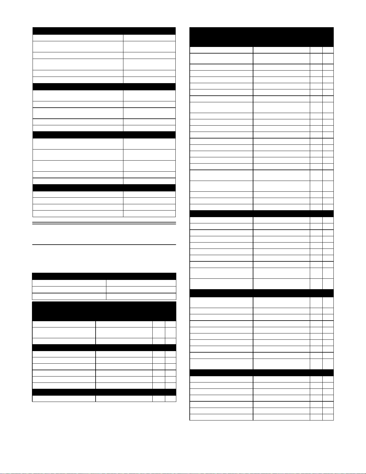
Torque Specifications
NOTE: Torque specifications have the following tol-
erances:
* w/Blue Loctite #243 ** w/Red Loctite #271
*** w/Green Loctite #270 **** w/“Patch-Lock”
CRANKSHAFT (500)
Connecting Rod (small end) (max) 20.021 mm
Connecting Rod (big end side-to-side)
(max) 0.7 mm
Connecting Rod (big end width) 21.95-22.00 mm
Connecting Rod (small end deflection)
(max) 3.0 mm
Crankshaft (web-to-web) 60.9 mm
Crankshaft Runout (max) 0.03 mm
CRANKSHAFT 700)
Connecting Rod (small end inside (max)
(diameter)
23.021 mm
Connecting Rod (big end side-to-side)(min) 0.6 mm
Connecting Rod @ 150 mm (max)
(small end deflection)
0.3 mm
Crankshaft (web-to-web) (min) 71 mm
Crankshaft Runout (max) 0.03 mm
CAMSHAFT AND CYLINDER HEAD (500)
Cam Lobe Height (min) (intake)
(exhaust)
34.71 mm
34.48 mm
Camshaft Journal Holder(right & center)
Inside Diameter (left)
22.01-22.04 mm
17.51-17.54 mm
Camshaft Journal Outside(right & center)
Diameter (left)
17.466-17.480 mm
21.966- 21.980 mm
Camshaft Runout (max) 0.03 mm
Cylinder Head/Cover Distortion (max) 0.05 mm
CAMSHAFT AND CYLINDER HEAD (700)
Cam Lobe Height (min) 33.53 mm
Camshaft Journal Oil Clearance (max) 0.04 mm
Camshaft Runout (max) 0.05 mm
Cylinder Head/Cover Distortion (max) 0.05 mm
Torque (ft-lb) Tolerance
0-15 ±20%
16-39 ±15%
40+ ±10%
EXHAUST COMPONENTS
Part Part Bolted To Torque
ft-lb N-m
Exhaust Pipe Cylinder Head 20 27
Spark Arrester Muffler 50
in.-lb
5
O2 Sensor Exhaust Pipe 19 26
BRAKE COMPONENTS
Brake Disc** Hub 15 20
Brake Hose Caliper 20 27
Brake Hose Master Cylinder 20 27
Master Cylinder Frame 25 34
Caliper**** Knuckle 20 27
Rear Driveline **** Rear Differential 12 16
ELECTRICAL COMPONENTS
Coil* Frame 811
DRIVE TRAIN COMPONENTS
Part Part Bolted To Torque
ft-lb N-m
Rear Differential/Gear Case Frame 38 48
Front Engine Mounting
Bracket
Frame 45 61
Rear Engine Mounting Bracket Frame 45 61
Engine Mounting Through-Bolt Frame 40 54
Front Differential Frame/Differential Bracket 38 52
Rear Output Flange Rear Driven Flange 40 54
Input Shaft Assembly Gear Case Housing 23 31
Pinion Housing Differential Housing 23 31
Secondary Shaft Bearing
Housing
Crankcase 28 38
Rear Cradle Frame 25 34
Driveshaft (Front/Rear) Engine 20 27
Shift Cable Bracket Engine 811
Front Input Drive Flange Front Drive Yoke Flange 20 27
Differential Housing Cover*** Differential Housing 23 31
Thrust Button** Gear Case Cover 811
Drive Bevel Gear Nut*** Shaft 87 118
Lock Collar Differential Housing 125 170
Hub Nut Front/Rear Shaft/Axle (min) 200 272
Oil Drain Plug Front Differential - Rear
Drive 45
in.-lb
5
Oil Fill Plug Front Differential - Rear
Drive 16 22
Oil Drain Plug Engine 16 22
Wheel (Aluminum) Hub 80 108
Wheel (Steel) Hub 40 54
STEERING COMPONENTS
Steering Wheel** Steering Wheel Shaft 25 34
Steering Wheel Shaft*** Intermediate Shaft (Upper) 31 42
Intermediate Shaft (Lower)*** Steering Pinion Shaft 36 49
Rack and Pinion Assembly Frame 35 48
Tie Rod Rack 37 50
Tie Rod End** Knuckle 30 41
Jam Nut Tie Rod End 10 14
Intermediate Shaft Coupler Intermediate Shaft 31 42
Steering Shaft Housing (6
mm)
Frame 811
Steering Shaft Housing (8
mm)
Frame 20 27
CHASSIS/ROPS ASSEMBLY
Shift Axle Support Frame 48
in.-lb
5
Front/Rear ROPS Tube Arm Rest/Steering Support 35 48
Top ROPS Support Front/Rear ROPS Tubes 35 48
Rear ROPS Tube Lower ROPS Support 35 48
Shift Cable Shift Arm Stud 834
Shift Cable Mounting/Adjuster Shift Cable 20 27
Cargo Box Hinge Cargo Box Frame 20 27
Side Panel/Spacer Cargo Box Frame 25 34
Tilt Pivot Bushing Cargo Box Frame 15 20
Latch Striker Cargo Box Liner 60
in.-lb
7
SUSPENSION COMPONENTS
A-Arm Frame 35 48
Knuckle Ball Joint 35 48
Shock Absorber Frame/Upper A-Arm 35 48
Shock Absorber (Front) Lower A-Arm 20 27
Shock Absorber (Rear) Lower A-Arm 35 48
Knuckle A-Arm 35 48
Sway Bar Bracket (Rear) Frame 35 48
This manual suits for next models
2
Table of contents


