Torrot KIDS10/12 Operating instructions

REPAIR MANUAL FOR THE ELECTRICAL SYSTEM / ELECTRONIC
MOTORCYCLES TORROT KIDS10/12
(Rev.1.0)

2 of 20 www.torrotelectric.com Rev. 1.0
REPAIR MANUAL
KIDS10/12
fdsafasdfasdf
R

3 of 20 www.torrotelectric.com Rev. 1.0
REPAIR MANUAL
KIDS10/12
fdsafasdfasdf
R
INDEX
Connection scheme V1.0 (P.4)
Connection scheme V1.1 (P.5)
System elements V1.0 (P.6)
System elements V1.1 (P.8)
Troubleshooting V1.0 (P.10)
Troubleshooting V1.1 (P.12)
Battery check (P.14)
Correct use of the battery (P.15)
Installation modifications (P.17)
Sequence of motor sensors (P.19)

4 of 20 www.torrotelectric.com Rev. 1.0
REPAIR MANUAL
KIDS10/12
fdsafasdfasdf
R
CONNECTION SCHEME (V1.0)
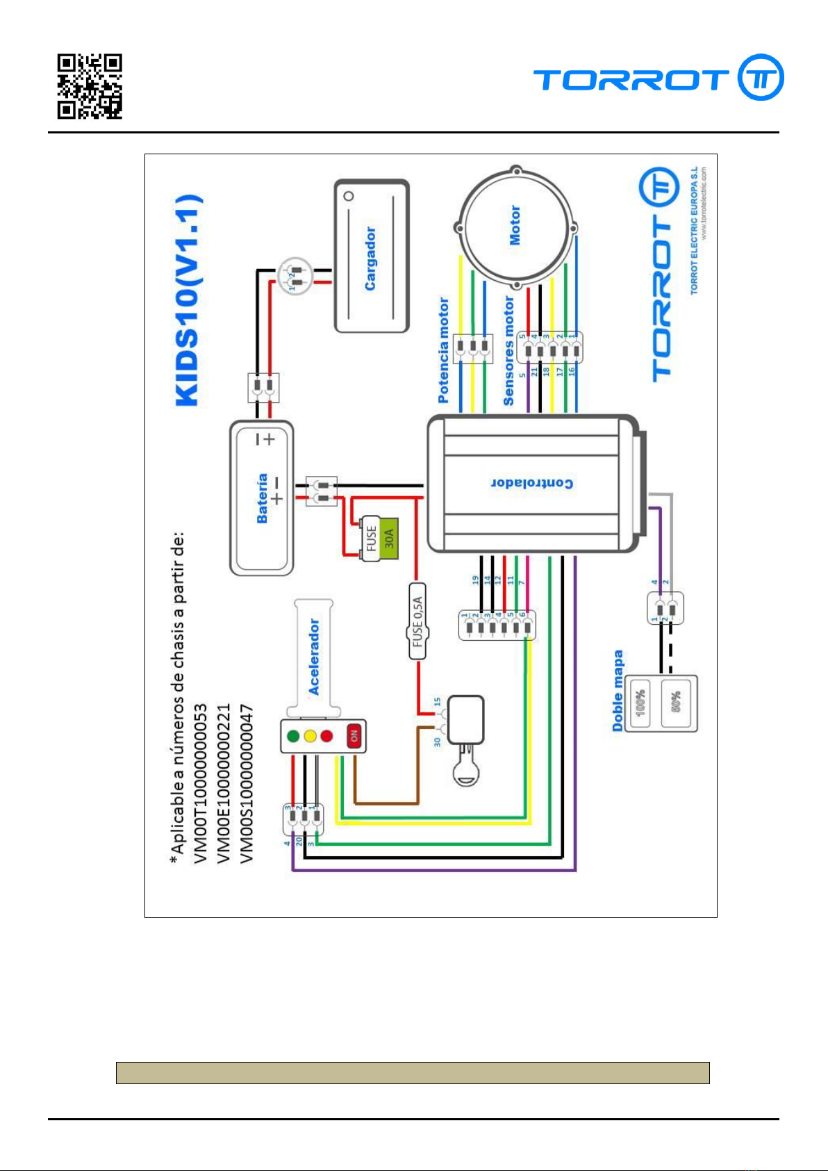
CONNECTION SCHEME (V1.1)
5 of 20 www.torrotelectric.com Rev. 1.0
REPAIR MANUAL
KIDS10/12
fdsafasdfasdf
R
RESUMEN DE ELEMENTOS (V1.0)
1: BATTERY
6 of 20 www.torrotelectric.com Rev. 1.0
REPAIR MANUAL
KIDS10/12
fdsafasdfasdf
R
Cables:
Red 1 and 2: Output, 48V
Cables:
Black 1: Common discharge
Cables:
Black 2: Common charge
2: CONTROLLER
Power
Cables:
Red: Input , direct battery voltage
Black: Common
Double map
Cables:
Yellow (4): Output, 4.3V
White (2): Common
Hall connector
Cables:
Yellow (4): Output, 4.5V
Black (21): Common
Yellow (18): Input Hall C, 4.5V
Green (17): Input Hall B, 4.5
Blue (16): Input Hall A, 4.5V
Motor phases
Cables:
Yellow: Output, Phase C
Green: Output, Phase B
Blue: Output, Phase A
Throttle
Cables:
Yellow (4): Output, 5V
Black (20): Common
Grey (3): Input, 0.8-4.2V
Connector E/S
Cables:
Black (19): Not connected
Black, Blue (14): Not connected
White (12): Not connected
Grey (11): Not connected
Pink (7): Input Start, Direct battery voltage
Start Line
Cables:
Red: Direct battery voltage
3: FUSES
Main fuse
Calibre
30A
Starting fuse
Calibre
0.5A
4: MOTOR
Hall connector
Cables:
Red: Input, 4.5V
Black: Common
Yellow (Output Hall C, 4.5V)
Green (Output Hall B, 4.5V)
Blue (Output Hall A, 4.5V)
7 of 20 www.torrotelectric.com Rev. 1.0
REPAIR MANUAL
KIDS10/12
fdsafasdfasdf
R
Motor phases
Cables:
Yellow (Input, Phase A)
Green (Input, Phase B)
Blue (Input, Phase C)
Winding resistance:
0,2-0,3 Ohms between terminals
5: DOUBLE MAP SELECTOR
Cables:
Black: Input, 4.5V
White / Black: Common
6: THROTTLE
Cables:
Red: Input, 5V
Black: Common
White: Output, 0.8-4.2V
Green: Output Start, direct battery voltage.
Yellow: Input Start, direct battery voltage.
8 of 20 www.torrotelectric.com Rev. 1.0
REPAIR MANUAL
KIDS10/12
fdsafasdfasdf
R
RESUMEN DE ELEMENTOS (V1.1)
1: BATTERY
Cables:
Red 1 and 2: Output, 48V
Cables:
Black 1: Common discharge
Cables:
Black 2: Common charge
2: CONTROLLER
Power
Cables:
Red: Input, direct battery voltage
Black: Common
Double map
Cables:
Violet (4): Output, 4.3V
Grey: Common
Hall connector
Cables:
Violet (4): Output, 4.5V
Black (21): Common
Yellow (18): Input Hall A, 4.5V
Green (17): Input Hall B, 4.5
Blue (16): Input Hall C, 4.5V
Motor phases
Cables:
Yellow: Output, Phase A
Green: Output, Phase B
Blue: Output, Phase C
Throttle
Cables:
Violet (4): Output, 5V
Black (20): Common
Green (3): Input, 0.8-4.2V
Connector E/S
Cables:
Black (19): Not connected
Black (14): Not connected
Red (12): Not connected
Green (11): Not connected
Pink (7): Input Start, direct battery voltage
Start Line
Cables:
Red: Direct battery voltage
3: FUSES
Main fuse
Calibre
30A
Starting fuse
Calibre
0.5A
9 of 20 www.torrotelectric.com Rev. 1.0
REPAIR MANUAL
KIDS10/12
fdsafasdfasdf
R
4: MOTOR
Hall connector
Cables:
Red: Input, 4.5V
Negro: Common
Amarillo (Output Hall A, 4.5V)
Green (Output Hall B, 4.5V)
Blue ( Output Hall C , 4.5V)
Phases motor
Cables:
Yellow (Input, Phase A)
Green (Input, Phase B)
Blue (Input, Phase C)
Winding resistance:
0,2-0,3 Ohms between terminals
5: DOUBLE MAP SELECTOR
Cables:
Black: Input, 4.5V
White / Black: Common
6: THROTTLE
Cables:
Red: Input, 5V
Black: Common
White: Output, 0.8-4.2V
Yellow + Green: Output Start + input indicator, direct battery
voltage.
Brown: Input Start, direct battery voltage.
7: KEY SWITCH
Cables:
Contact 15: Input, direct battery voltage
Contact 30: Output, direct battery voltage
10 of 20 www.torrotelectric.com Rev. 1.0
REPAIR MANUAL
KIDS10/12
fdsafasdfasdf
R
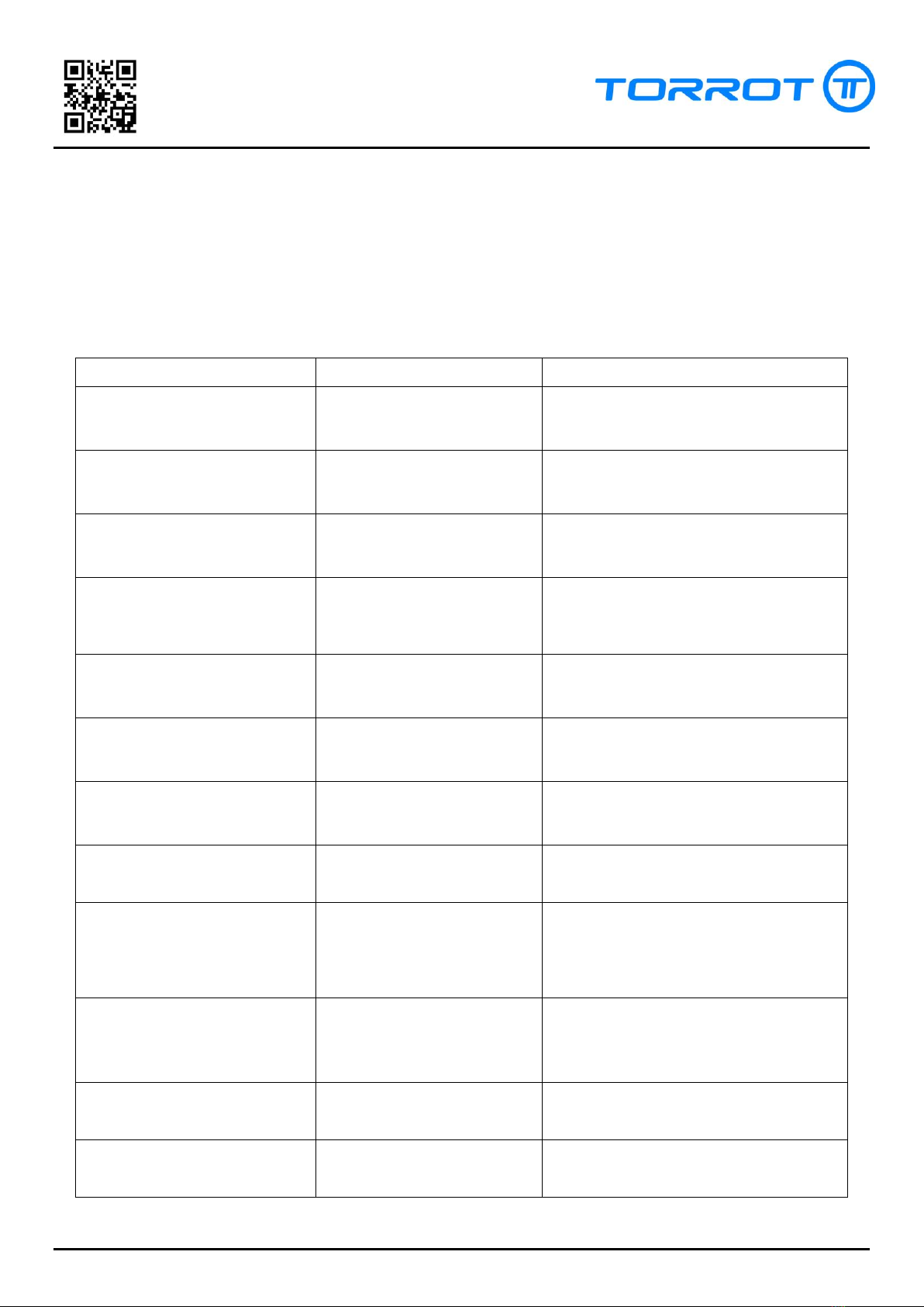
TROUBLESHOOTING (V1.0)
The following table helps you to detect and solve common problems. Before using it and as
a step prior to the solution of problems, make sure that the battery is fully charged and that you
have entered a set of parameters known in the controller, in this order. If you cannot charge the
battery or enter the parameters in the controller, please read first the corresponding possible
causes in the table.
PROBLEM
POSSIBLE CAUSES
ERROR DETECTION/ SOLUTION
Pressing the ON button the motor
does not respond
Low battery
Check voltage in the discharge terminals of
the battery. Charge the battery.
Main fuse damaged
Check the 30A power fuse. Check for possible
short circuits in the wiring / controller.
Replace the fuse when it is safe.
Starting fuse damaged
Check the 0.5A starting fuse. Check for
possible short circuits in the wiring /
controller. Replace the fuse when it is safe.
The Start signal does not reach
the E/S connector
Check the wiring of the whole circuit and that
the battery voltage reaches cable 7 (pink) of
the E/S connector. Replace defective points of
the installation.
There is tension in the Start line but
the motor does not respond
The controller does not transmit
voltage to the throttle
Disconnect the throttle and check that there is
supply voltage in the supply line of the
throttle. Replace the controller if necessary.
The throttle is defective
Once checked that there is supply voltage
check the analogue signal of the throttle.
Replace the throttle if necessary.
When the motor is activated, it
emits an unusual sound or vibrates
excessively
Connection error in the Hall
sensors
Check the connection of the Hall sensors.
Check the continuity on both sides of the
connector. Replace the connector if necessary.
Disconnection of any of the
motor phases or error in the
order of the connections.
Check the connectors of the motor phases.
The controller does not supply
voltage to the sensors correctly.
Disconnect the controller and check the
power supply of the Hall sensors. Connect and
check again. Check that the sensors are
correctly supplied with voltage. According to
the results replace controller and/or motor.
One or more sensors do not
generate position signals.
With the motor in start position, turn the
motor manually. Check if the signals of the
Hall sensors vary by turning the motor.
Replace the motor if necessary.
One or more of the phases have
deteriorated.
Check that the resistance of the windings is
the correct one and that there are no
derivations to the chassis.
Excessive resistance to the
rotation of the motor.
Check manually if the wheel can turn easily.
Solve possible problems in the chassis /
braking system.
11 of 20 www.torrotelectric.com Rev. 1.0
REPAIR MANUAL
KIDS10/12
fdsafasdfasdf
R
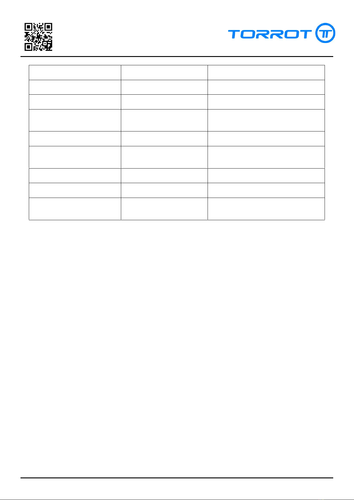
Dual map button does not work
Connection error in the switch.
Check connections of the dual map switch.
Replace defective parts.
Dual map switch defective
Check the continuity in the switch. Replace if
necessary.
Programming error.
Programme a parameter set in the controller.
Restart the controller and check the function.
The controller does not supply
voltage to the dual map switch
Disconnect the switch. Check that there is the
necessary voltage in the supply line of the
switch.
When the charger is connected the
indicator light stays green.
Battery is fully charged
Check the battery voltage. If fully charged it
will not accept any more charging.
Wiring error
Check that there is battery voltage in the
circular chassis connector and in the battery
charging connector. Replace defective parts.
The battery is defective
Follow the instructions of the battery check.
Replace battery if necessary.
It is not possible to programme the
controller.
The controller is not supplied with
power and in position Start.
Check all steps of the initial section. Keep the
motor activated in order to programme.
Wrong connection cable
Check that the connection cable is in good
condition and correctly connected and
installed on your PC.

12 of 20 www.torrotelectric.com Rev. 1.0
REPAIR MANUAL
KIDS10/12
fdsafasdfasdf
R
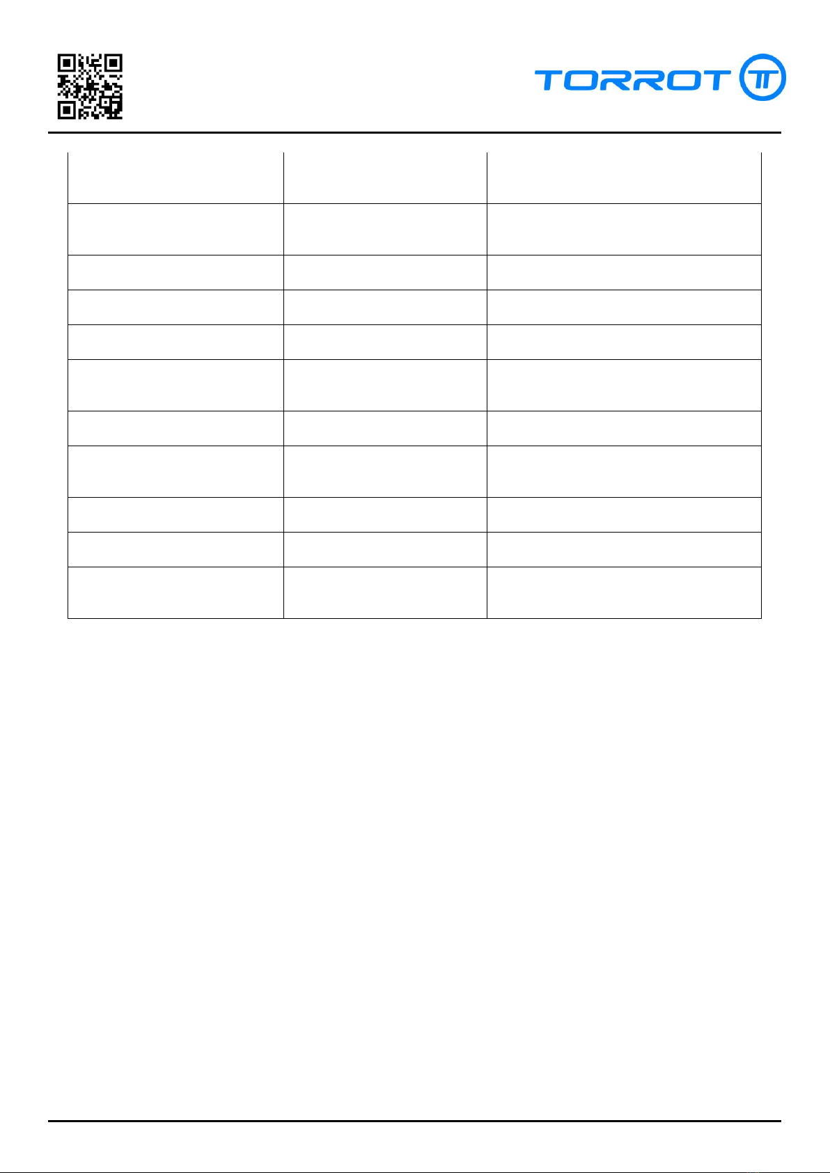
TROUBLESHOOTING (V1.1)
The following table helps you to detect and solve common problems. Before using it and as
a step prior to the solution of problems, make sure that the battery is fully charged and that you
have entered a set of parameters known in the controller, in this order. If you cannot charge the
battery or enter the parameters in the controller, please read first the corresponding possible
causes in the table.
PROBLEM
POSSIBLE CAUSES
ERROR DETECTION/ SOLUTION
Pressing the ON button the
indicator does not light up and the
motor does not respond
Low battery
Check voltage in the discharge terminals of
the battery. Charge the battery.
Main fuse damaged
Check the 30A power fuse. Check for possible
short circuits in the wiring / controller.
Replace the fuse when it is safe.
Starting fuse damaged
Check the 0.5A starting fuse. Check for
possible short circuits in the wiring /
controller. Replace the fuse when it is safe.
The key switch does not start
Check that the key switch is in the ON
position. Turn the key to the correct position.
The key switch does not work
Check that there is battery voltage in the
terminal before turning the key and that the
terminals 15 and 30 connect when starting the
switch. Replace the switch if necessary.
The Start signal does not reach
the E/S connector
Check the wiring of the whole circuit and that
the battery voltage reaches cable 7 (pink) of
the E/S connector. Replace defective points of
the installation.
The indicator responds and there is
tension in the Start line but the
motor does not respond
The controller does not transmit
voltage to the throttle
Disconnect the throttle and check that there is
supply voltage in the supply line of the
throttle. Replace the controller if necessary.
The throttle is defective
Once checked that there is supply voltage
check the analogue signal of the throttle.
Replace the throttle if necessary.
When the motor is activated, it
emits an unusual sound or vibrates
excessively
Connection error in the Hall
sensors
Check the connection of the Hall sensors.
Check the continuity on both sides of the
connector. Replace the connector if necessary.
Disconnection of any of the
motor phases or error in the
order of the connections.
Check the connectors of the motor phases.
The controller does not supply
voltage to the sensors correctly.
Disconnect the controller and check the
power supply of the Hall sensors. Connect and
check again. Check that the sensors are
correctly supplied with voltage. According to
the results replace controller and/or motor.
One or more sensors do not
generate position signals.
With the motor in start position, turn the
motor manually. Check if the signals of the
Hall sensors vary by turning the motor.
Replace the motor if necessary.
13 of 20 www.torrotelectric.com Rev. 1.0
REPAIR MANUAL
KIDS10/12
fdsafasdfasdf
R
One or more of the phases have
deteriorated.
Check that the resistance of the windings is
the correct one and that there are no
derivations to the chassis.
Excessive resistance to the
rotation of the motor.
Check manually if the wheel can turn easily.
Solve possible problems in the chassis /
braking system.
Dual map button does not work
Connection error in the switch.
Check connections of the dual map switch.
Replace defective parts.
Dual map switch defective
Check the continuity in the switch. Replace if
necessary.
Programming error.
Programme a parameter set in the controller.
Restart the controller and check the function.
The controller does not supply
voltage to the dual map switch
Disconnect the switch. Check that there is the
necessary voltage in the supply line of the
switch.
When the charger is connected the
indicator light stays green.
Battery is fully charged
Check the battery voltage. If fully charged it
will not accept any more charging.
Wiring error
Check that there is battery voltage in the
circular chassis connector and in the battery
charging connector. Replace defective parts.
The battery is defective
Follow the instructions of the battery check.
Replace battery if necessary.
It is not possible to programme the
controller.
The controller is not supplied with
power and in position Start.
Check all steps of the initial section. Keep the
motor activated in order to programme.
Wrong connection cable
Check that the connection cable is in good
condition and correctly connected and
installed on your PC.
14 of 20 www.torrotelectric.com Rev. 1.0
REPAIR MANUAL
KIDS10/12
fdsafasdfasdf
R
BATTERY CHECK
The lithium-ion battery of KIDS10/12 has an integrated electronic energy
management, different from lead batteries that work without electronic control. This means
that the charging and discharging battery drivers are independent from each other being
able to have supply voltage in only one of them and not in the other.
During normal functioning there must always be supply voltage in the loading port
while the tension of the discharge port is 0V at the time when the battery is fully charged
and it stays like this until the battery is charged above the minimum limit.
There are some checks that can be done in case you think that the battery might not
work correctly.
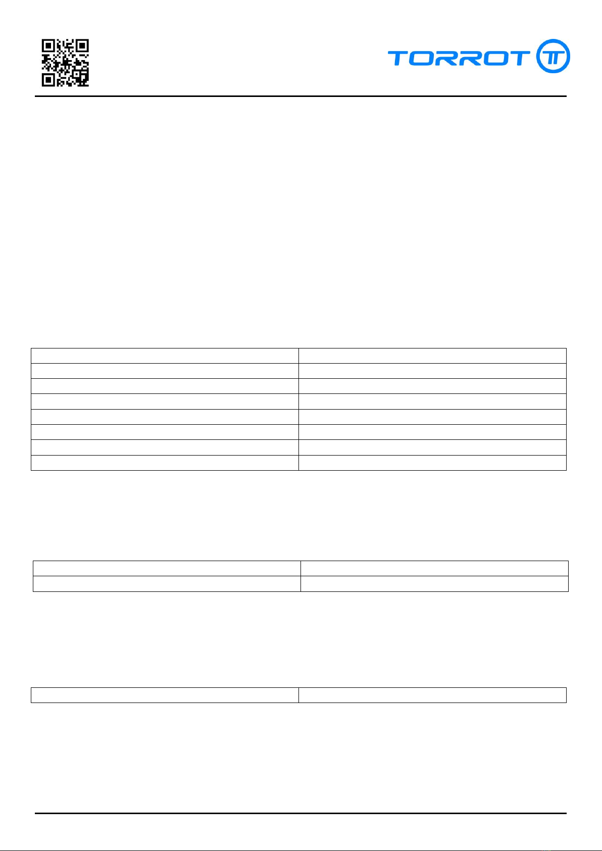
Checking the battery voltage: Although the battery's nominal voltage is 48V it should
reach 54.6V by the end of the charging process. If at the end of charging the battery
remains below this value it is an indication that there is an internal battery error. Usually this
error occurs with the fact that the LED indicator of the charger changes the colour from red
to blue instead of to green. A third check is to measure the voltage at the charging and
discharging ports. With the values obtained consult the following table:
BATTERY STATES
Voltage at charging port
Voltage at discharging port
State
36V –54.6V (equal to
discharging port)
36V –54.6V (equal to
charging port)
Ok
0V
36V –54.6V
Internal error
36V –54.6V
0V
Battery discharged
0V
0V
Internal error / overheating

15 of 20 www.torrotelectric.com Rev. 1.0
REPAIR MANUAL
KIDS10/12
fdsafasdfasdf
R
CORRECT USE OF THE BATTERY
1. General
a. The motorcycle battery is composed of lithium-ion cells with high energy
density. In no case it must be manipulated. Non-compliance with this advice
involves electrical and chemical risks and can result in material damage and
serious personal injuries.
b. It is strictly prohibited that personnel not authorized explicitly by the
manufacturer carry out inspection, repair or replacement of the battery or any
of its elements.
2. Damages to the battery
a. All abusive treatment of the vehicle can affect the life of the battery. To keep it
in good condition and to extend its life the following instructions must be
followed:
i. Avoid using the motorcycle in conditions of extreme heat or cold that
exceed the limits specified by the manufacturer.
ii. Avoid charging the battery in conditions of extreme heat or cold that
exceed the limits specified by the manufacturer.
iii. In periods when the vehicle is not used it must be stored in a dry place
away from sources of cold and/or heat as well as from direct sunlight.
iv. Avoid unnecessary blows and vibrations on your motorcycle. Check
regularly that the insulation between the battery and the chassis of the
vehicle is in good condition. If it is not replace it.
v. The auto discharge is a natural characteristic of the battery and must be
controlled. For long periods of inactivity periodically connect the charger
and charge the battery completely.
vi. Avoid partial charges of the battery. For a correct daily use the battery
must always be charged until the charger completes the process
indicating it with the green light.
vii. As a general rule it is recommended to keep the battery connected to
the charger for a few minutes after the completion of charging.
viii. Do not use any charger that has not been directly supplied by the
manufacturer.
ix. Avoid forcing the vehicle in an abnormal way during its use.
16 of 20 www.torrotelectric.com Rev. 1.0
REPAIR MANUAL
KIDS10/12
fdsafasdfasdf
R
x. The battery is provided with internal protections against electrical
hazards that can work automatically. Go to the section on battery check
to know how to proceed.
xi. Keep the battery clean and in good condition, carefully remove dust, dirt
and other external elements that could get into the battery
compartment during its use.
xii. In case of detecting damage in the drivers of the electrical system,
disconnect the vehicle and remove it from the power supply before
proceeding with the repair. Do not reconnect until you have made sure
that there are no unwanted derivations.
xiii. Avoid direct contact of the electrical system of the motorcycle with
water, mud or similar. If water accidentally gets into any electrical
element of the vehicle disconnect it and wait for it to dry naturally prior
to its inspection/repair.
17 of 20 www.torrotelectric.com Rev. 1.0
REPAIR MANUAL
KIDS10/12
fdsafasdfasdf
R
MODIFICATIONS IN THE INSTALLATION
To make the modifications listed below check the schemes of both installations and compose the
installation as shown in the document. Pay special attention to the position of the cables in the contacts
and to their type. The diagram shows the types of contacts that are inside the connectors.
Before modifying the installation remove as many elements of the fairing as necessary to work
comfortably and remove the battery
REPLACEMENT OF CONTROLLER V1.0 FOR V1.1
Reference manufacturer kit:
01EL-000A0-ZZ
KIT CONNECTOR WP 2 PINS
01EL-000B0-ZZ
KIT CONNECTOR WP 3 PINS
01EL-000C0-ZZ
KIT CONNECTOR WP 5 PINS
01EL-000D0-ZZ
KIT CONNECTOR WP 6 PINS
01EL-000E0-ZZ
KIT ANDERSON PP30 RED
01EL-000F0-ZZ
KIT ANDERSON PP30
01EL-000G0-ZZ
KIT ANDERSON PP30
01EL-000H0-ZZ
KIT ANDERSON PP30 GREEN
REPLACEMENT OF THROTTLE CONTROL V1.0 FOR V1.1
Reference manufacturer kit:
01EL-00020-ZZ
THROTTLE ELEC. LOAD LEVEL WP.
01EL-000B0-ZZ
KIT CONNECTOR WP 3 PINS
ADDITION OF KEY SWITCH TO INSTALLATION V1.0
Reference manufacturer kit:
01EL-00110-ZZ
KEY SWITCHED ON
CHANGE OF ALL CONNECTORS V1.0 FOR V1.1 (WATERPROOF)
Reference manufacturer kit:
18 of 20 www.torrotelectric.com Rev. 1.0
REPAIR MANUAL
KIDS10/12
fdsafasdfasdf
R
01EL-000E0-ZZ
KIT ANDERSON PP30 RED
01EL-000F0-ZZ
KIT ANDERSON PP30 BLACK
01EL-000G0-ZZ
KIT ANDERSON PP30 YELLOW
01EL-000H0-ZZ
KIT ANDERSON PP30 GREEN
01EL-000I0-ZZ
KIT ANDERSON PP30 BLUE
01EL-00110-ZZ
KEY SWITCHED ON REF. 6553
01EL-00210-ZZ
FUESE HOLDER RUBBER WP. 30A
01EL-000A0-ZZ
KIT CONNECTOR WP 2 PINS
01EL-000B0-ZZ
KIT CONNECTOR WP 3 PINS
01EL-000C0-ZZ
KIT CONNECTOR WP 5 PINS
01EL-000D0-ZZ
KIT CONNECTOR WP 6 PINS
INSTALLATION OF REMOVABLE BATTERY IN INSTALLATION V1.0
Reference manufacturer kit:
01EL-000E0-ZZ
KIT ANDERSON PP30 RED
01EL-000F0-ZZ
KIT ANDERSON PP30 BLACK
REPLACING OF CHARGING CONNECTOR V1.0 FOR V1.1
Reference manufacturer kit:
01EL-000A0-ZZ
KIT CONNECTOR WP 2 PINS
01PW-00041-ZZ
BATTERY CHARGING CABLE WAT.

19 of 20 www.torrotelectric.com Rev. 1.0
REPAIR MANUAL
KIDS10/12
fdsafasdfasdf
R
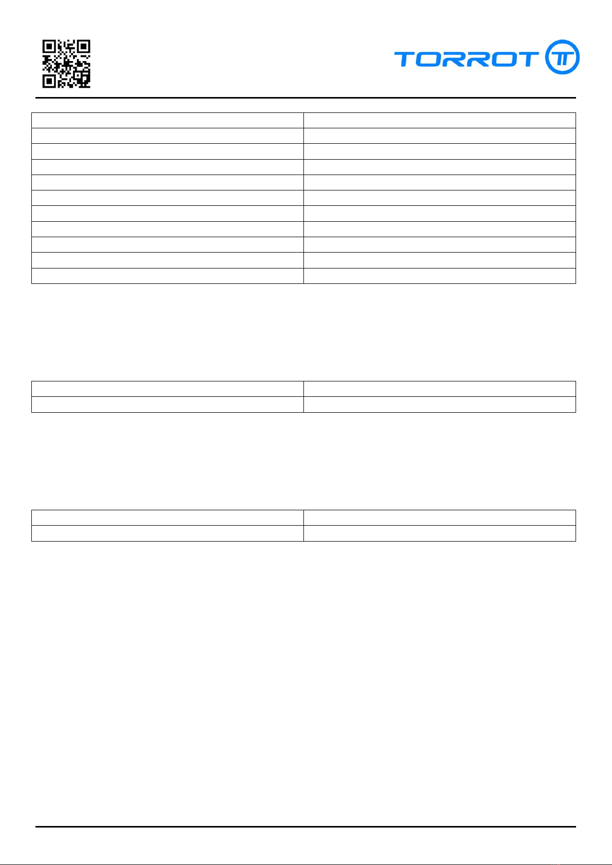
ANNEX 1: SEQUENCE OF MOTOR SENSORS
Sequence of the motor Hall sensors (1= On, 0=Off)
Hall A (Blue)
Hall B (Green)
Hall C (Yellow)
1
0
0
1
1
0
0
1
0
0
1
1
0
0
1
1
0
1

20 of 20 www.torrotelectric.com Rev. 1.0
REPAIR MANUAL
KIDS10/12
fdsafasdfasdf
R
Table of contents
Other Torrot Motorcycle manuals


Popular Motorcycle manuals by other brands


KTM
KTM 250 EXC-F EU 2012 Setup instructions

BMW Motorrad
BMW Motorrad R 1250 RT special vehicle 2018 Rider's manual

MOTO GUZZI
MOTO GUZZI Stelvio 1200 NTX ABS MY10 Service station manual

Yamaha
Yamaha 2001 V Star XVS1100AN owner's manual

Yamaha
Yamaha XSR 700 owner's manual

Zontes
Zontes ZT310T-M Maintenance manual


