TRACE ELLIOT ACOUSTIC P.A User manual

OPERATING
INSTRUCTIONS
DEDICATED
ACOUSTIC PA
SYSTEM
ACOUSTIC P.A

TRACE ACOUSTIC P.A. is a high quality, compact sound system that is unique in its ability
to accept signal inputs from virtually any source.
Inputs and channels are provided that will accept inputs from any of the following sound
sources: Acoustic instruments with built in preamp ( Active )
Acoustic instruments with just a Piezo pick up ( Passive )
Acoustic instruments with microphone pick up
Direct from electric guitars
Direct from Bass guitars
Direct from stereo guitar multi effects units
Stereo keyboards
Midi voice modules
CD players
Mini Disc
Tape or cassette machines
Drum machines
Vocal microphones etc. etc.
The use of the mixer section with all of the above will be covered within the descriptions of
the various channels available on this unit.
TRACE ACOUSTIC P.A. was developed with specific applications in mind. Firstly for a small
group of acoustic musicians that require some appropriate, high quality sound
reinforcement that can be completely
self contained and be used as a full system catering for acoustic
instruments, vocals, keyboards and backing tapes if required all with
built in digital effects adjustable in level for each individual mixer channel. With the MONO
MIX output that can be used to drive monitors everything that would be required in a
modest live situation is catered for.
Secondly for the single performer or Duo entertainer with either a keyboard or guitar
( acoustic or electric ) based act with backings from a variety of sources.
The requirement here is for a good quality system capable of a fair bit of power if required
( thus the powered Sub Bass option ) with a suitable range of inputs to allow everything to
go through the P.A. and thus minimise the need for any other ancillary
or backline equipment ( less to carry around ).
TRACE ACOUSTIC PA is a complete system including the mixer, the power amplifiers and
the specially developed speakers. It is able to be a very compact system because it has
been developed as a system, where the internal power amplifiers and electronic
crossovers have been designed to exactly compliment the abilities of the speaker cabinets.
3
Internal electronic processor systems have been used to dynamically modify the response
of the speakers to maintain a high quality sound at what ever level the system is used at.
THE SYSTEM
The system is supplied with
1. The powered mixer.
2. The speaker cabinets x 2.
3.The Speakon cables x 2 for connecting the powered mixer to the speaker cabinets.
4. The mains power cable.
The Speakon cables are attached to the sockets on the rear of the powered mixer. To do
this insert the Speakon plug into the socket with the large locating key uppermost, then
turn the plug to the right until the latch clicks into place. Do the same at the speaker
cabinet end.
The mains power cable is connected to the mains socket also on the rear of the
powered mixer. The mains fuse is located just below this socket and in the event of having
to replace this check the type and rating as printed on the rear panel and replace only with
one of the correct type and rating.
Once connected to the mains power and the speaker cabinets the system may be turned
on with the mains switch also located on the rear panel. An LED located just above the
bargraphs on the front panel will illuminate to indicate when the unit is powered up.
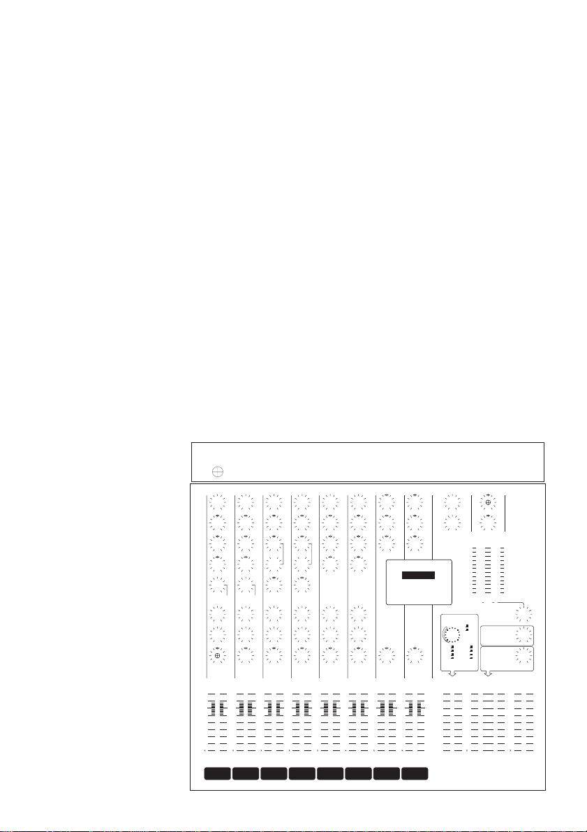
THE MIXER
ACOUSTIC CHANNELS
Channels 1 & 2 are
ACOUSTIC INSTRUMENT
channels with a range of
facilities and EQ
specifically
designed to best suit
acoustic
instruments. These
channels
are unique to this mixer
and
provide facilities not
usually
found on mixers.
-20
-10
-7
-4
-3
-2
-1
+1
+2
+3
+4
-20
-10
-7
-4
-3
-2
-1
+1
+2
+3
+4
GAIN
HIGH
MID
LOW
NOTCH
AUX 2
PAN
DSP / AUX 1
IN/OUT
+
_
+
_
+
_
RL
GAIN
HIGH
MID
LOW
NOTCH
AUX 2
PAN
DSP / AUX 1
IN/OUT
+
_
+
_
+
_
RL
GAIN
HIGH
MID
+
_
+
_
MID FREQ
LOW +
_
AUX 2
PAN
DSP / AUX 1
RL
200 8k
2k
GAIN
HIGH
MID
+
_
+
_
MID FREQ
LOW +
_
AUX 2
PAN
DSP / AUX 1
RL
200 8k
2k
AUX 2
BALANCE
DSP / AUX 1
RL
AUX 2
DSP / AUX 1
RL
BALANCE
GAIN
HIGH
MID
LOW
+
_
+
_
+
_
GAIN
HIGH
MID
LOW
+
_
+
_
+
_
HIGH
MID
LOW
+
_
+
_
+
_
HIGH
MID
LOW
+
_
+
_
+
_
HIGH +
_
LOW +
_
AUX 2
AUX 1
SOLO
SUB LEVEL
PHONES
POWER AMP
LEVEL
SOLO SOLO SOLO SOLO SOLO SOLO SOLO SOLO
-10
-5
0dB
-15
-20
-25
-30
-40
-oo
-10
-5
0dB
-15
-20
-25
-30
-40
-oo
1 2 3 4 5/6 7/8 DSP EFFECT
LEVEL MASTER
FADERS MONO MIX
LEVEL
LR
MIN
DECAY / DELAY BRIGHT
DARK
DELAY
PLATE
ROOM
HALL
21 3 4 5/6 7/8 9/10 11/12
DESIGNED AND MADE IN ENGLAND BY:-
TRACE ELLIOT LIMITED, MALDON, ESSEX.
RL
AUX SENDS OUTPUT EQ
SYSTEM PA 12-2/300
300 WATT, TRI-AMPED
ACOUSTICALLY ENGINEERED
HIGH QUALITY PA SYSTEM
IN/OUT
STEREO GUITAR
SPEAKER EMULATION
RL
BALANCE RL
BALANCE
DSP (Digital Signal
Processor) CONTROL
USE 'POWER AMP LEVEL' IN
COMBINATION WITH
'MASTER FADERS' TO SET
OVERALL PERFORMANCE
VOLUME
FOR USE WITH ADDITIONAL
'SUB BASS' ENCLOSURE
AND AMPLIFIER
( FOR MONITORS )
0dB
+5
+10
-5
-10
-20
-30
-40
-oo
0dB
+5
+10
-5
-10
-20
-30
-40
-oo
0dB
+5
+10
-5
-10
-20
-30
-40
-oo
0dB
+5
+10
-5
-10
-20
-30
-40
-oo
0dB
+5
+10
-5
-10
-20
-30
-40
-oo
0dB
+5
+10
-5
-10
-20
-30
-40
-oo
0dB
+5
+10
-5
-10
-20
-30
-40
-oo
0dB
+5
+10
-5
-10
-20
-30
-40
-oo
SHAPE SHAPE
PEAK PEAK PEAK PEAK PEAK PEAK PEAK PEAK
0dB 0dB
ACOUSTIC
TRACE
9/10 11/12
SOLO
SUB LEVEL
PHONES
POWER AMP
LEVEL
1 2 3 4 5/6 7/8 DSP EFFECT
LEVEL MASTER
FADERS MONO MIX
LEVEL
LR
21 3 4 5/6 7/8 9/10 11/12
TRACE ELLIOT LIMITED, MALDON, ESSEX.
RL
SYSTEM PA 12-2/300
0dB 0dB
0dB0dB
0dB 0dB 0dB 0dB 0dB 0dB 0dB 0dB
ACOUSTIC
TRACE
9/10 11/12
12
ACOUSTIC
CHANNELS
34
MIC CHANNELS STEREO
CHANNELS
5/6 7/8
STEREO
RETURNS
9/10 11/12
4

Inputs
There are 2 x inputs on each acoustic channel, these are PIEZO and ACTIVE.
The ACTIVE input is for use with any acoustic instrument that has a built in preamplifier
within the instrument itself and is designed to suit the lower impedance and higher
headroom that these preamps require.
The PIEZO input has a very high input impedance to suit that of any type of piezo
transducer, and should be used where there is no preamp between instrument and
amplifier. This will give the best possible quality of tone from the instrument. Should you
have an ACTIVE instrument that has a very low signal output then it may be better for you
to also use this input as it has a far greater signal sensitivity.
Gain Control
The GAIN control is used to set the level of signal through the channel. This should be set
so that the PEAK LED at the bottom of the channel just flashes on with playing peaks. It is
important to set this correctly as it ensures that you achieve the best
possible signal to noise ratio without adding distortion from signal clipping.
A better way to set this control accurately is to depress the SOLO button ( just above the
channel slider ) and read out the playing signal level on the Right and Left Bargraphs on
the right hand side of the mixer. Set the GAIN control so that the bargraphs just go into
the red on playing peaks.
After adjusting the EQ on the channel it may be necessary to readjust the GAIN
control to compensate for any increase or decrease in signal level provided by the
equalisation.
Equalisation - High, Mid, Low
The equalisation on the ACOUSTIC CHANNELS is specifically tailored to best suit acoustic
instruments, particularly acoustic guitar.
The 3 x EQ controls each provide 12dB of cut and boost at the following frequencies:
HIGH - 16kHz, MID - 630Hz, LOW - 100Hz.
Notch Filter
The NOTCH filter is a special circuit that removes a narrow band of frequencies from the
amplified signal in order to minimise the possibility of feedback at low frequencies due to
the body resonance of the instrument. This frequency ‘Notch’ is tuneable with the notch
control within the range 50Hz to 250Hz and is switched in and out of circuit with the
IN/OUT switch just below and to the right of the NOTCH control.
5

The NOTCH filter is IN circuit when the push button is depressed. If you have
problems with low frequency feedback then switch the notch filter into circuit and then
adjust the NOTCH control until the feedback goes away. If you continue to have problems
then the only answer is either move further away from the speakers or reduce the LOW EQ
or the overall volume slightly. In most cases the NOTCH filter alone will do the trick.
Shape Switch
Below the NOTCH control and to the left is the SHAPE switch. This switches a preset
equalisation that is appropriate to acoustic instruments into the channel when the push
button is depressed.
The SHAPE facility adds an instant ‘Sparkle’ to the sound that is useful for both rhythm
and fingerpicking styles of playing. It adds a boost at high and low frequencies and a slight
cut at mid frequencies.
DSP/Aux 1 Control
The DSP/AUX 1 control adjusts the level of signal from the channel sent to the internal
DIGITAL EFFECTS PROCESSOR ( DSP ) and also the level of signal sent to the
AUX 1 SEND jack socket for use with an external effects processors.
This control is post fader so that the level of effects set for the channel always stays in the
same proportion to the direct signal regardless of the position of the fader.
Aux 2 Control
The AUX 2 control adjusts the level of signal from the channel that is sent to the AUX 2
jack socket for use with an external effects processor. This control is also post fader as
explained above.
Pan Control
The PAN control sets the position of the channel signal within the stereo field.
It PANS the signal between the Right and Left master outputs.
Solo Button
The SOLO button allows the signal level through the channel to be read on the LEFT and
RIGHT BARGRAPH LED’s, this gives a clear indication of signal level and makes it easier to
set the channel GAIN control to the correct position.
When the SOLO button is depressed the channel PEAK LED is illuminated to indicate
which channel has its SOLO button down. Also the two LED’s below the bargraphs are
illuminated to indicate that these are now reading a solo channel.
The SOLO button also routes the channel signal to the PHONES output to allow the signal
to be monitored individually from all other signals going through the mixer. If no SOLO
buttons are depressed then the PHONES output monitors the Left and Right MASTER
outputs.
6

The SOLO facility is pre fader so that you can monitor the signal into the channel
even when the channel fader is fully down. This also routes the signal to the PHONES
output so that the incoming signal can still be listened to even when the channel fader is
fully down.
Channel Fader
The CHANNEL FADER sets the level of signal from each individual channel in the overall
mix.
For best results always try to keep the CHANNEL FADER around the 0dB ( Green Line )
position, this will give you maximum signal through the mixer and also minimum
background noise.
As a general rule keep the channel faders as high as possible and the MASTER FADERS as
low as possible for the best signal to noise ratio.
MIC CHANNEL
Inputs
The MIC CHANNEL has 2 x Inputs, the XLR input is a balanced low
impedance input to suit most kinds of microphone. The JACK input is a
line level input to suit such things as keyboard, tape, CD etc.
This channel is a fairly standard channel as found on most mixers.
The MIC CHANNELS on the TRACE ACOUSTIC PA are the only
conventional channels on this mixer.
Gain Control
The GAIN control is used to set the level of signal through the channel.
This should be set so that the PEAK LED at the bottom of the channel just
flashes on with signal peaks. It is important to set this correctly as it
ensures that you achieve the best possible signal to noise ratio without
adding distortion from signal clipping.
GAIN
HIGH
MID
+
_
+
_
MID FREQ
LOW +
_
AUX 2
PAN
DSP / AUX 1
RL
200 8k
2k
GAIN
HIGH
MID
+
_
+
_
MID FREQ
LOW +
_
AUX 2
PAN
DSP / AUX 1
RL
200 8k
2k
SOLO SOLO
345
34
0dB
+5
+10
-5
10
20
30
40
oo
0dB
+5
+10
-5
-10
-20
-30
-40
-oo
0d
+5
+1
-5
-1
-2
-3
-4
-o
PEAK PEAK
345
34
0dB 0dB 0d
7

A better way to set this control accurately is to depress the SOLO button ( just above the
channel slider ) and read out the signal level on the Right and Left Bargraphs on the right
hand side of the mixer. Set the GAIN control so that the bargraphs just go into the red on
signal peaks.
After adjusting the EQ on the channel it may be necessary to readjust the GAIN control to
compensate for any increase or decrease in signal level provided by the equalisation.
Equalisation - High, Mid, Mid Freq, Low
The equalisation on the MIC channel is fairly conventional with HIGH and LOW boost and
cut on separate controls and a swept MID allowing the frequency at which the MID is
boost or cut to be selected with the MID FREQ control.
All controls provide 12dB of boost or cut with the HIGH and LOW frequencies set at 10kHz
and 80Hz respectively and the MID able to be swept between 200Hz and 8kHz.
DSP/Aux 1 Control
The DSP/AUX 1 control adjusts the level of signal from the channel sent to the internal
DIGITAL EFFECTS PROCESSOR ( DSP ) and also the level of signal sent to the AUX 1
SEND jack socket for use with an external effects processors.
This control is post fader so that the level of effects set for the channel always stays in the
same proportion to the direct signal regardless of the position of the fader.
Aux 2 Control
The AUX 2 control adjusts the level of signal from the channel that is sent to the AUX 2
jack socket for use with an external effects processor. This control is also post fader as
explained above.
Pan Control
The PAN control sets the position of the channel signal within the stereo field. It PANS the
signal between the Right and Left master outputs.
Solo Button
The SOLO button allows the signal level through the channel to be read on the LEFT and
RIGHT BARGRAPH LED’s, this gives a clear indication of signal level and makes it easier to
set the channel GAIN control to the correct position.
8

When the SOLO button is depressed the channel PEAK LED is illuminated to indicate
which channel has its SOLO button down. Also the two LED’s below the bargraphs are
illuminated to indicate that these are now reading a solo channel.
The SOLO button also routes the channel signal to the PHONES output to allow the signal
to be monitored individually from all other signals going through the mixer. If no SOLO
buttons are depressed then the PHONES output monitors the Left and Right MASTER
outputs.
The SOLO facility is pre fader so that you can monitor the signal into the channel even
when the channel fader is fully down. This also routes the signal to the PHONES
output so that the incoming signal can still be listened to even when the channel fader is
fully down.
Channel Fader
The CHANNEL FADER sets the level of signal from each individual channel in the overall
mix.
For best results always try to keep the CHANNEL FADER around the 0dB ( Green Line )
position, this will give you maximum signal through the mixer and also minimum
background noise.
As a general rule keep the channel faders as high as possible and the MASTER FADERS as
low as possible for the best signal to noise ratio.
STEREO CHANNELS
The STEREO CHANNELS are once again special channels
unique to this mixer and provide facilities not usually found on mixers.
Inputs
The inputs to these channels are unique in that they are very high
impedance allowing either a guitar, bass or another acoustic
instrument to be plugged directly into the mixer and still maintain
a perfect tone from the instrument. Ever tried plugging directly into
a mixer before? It kills your tone, just try plugging your guitar into
the line input on the MIC channel if you want a comparison.
AUX 2
BALANCE
DSP / AUX 1
RL
AUX 2
DSP / AUX 1
RL
BALANCE
GAIN
HIGH
MID
LOW
+
_
+
_
+
_
GAIN
HIGH
MID
LOW
+
_
+
_
+
_
SOLO SOLO
5/6 7/8
5/6 7/8
IN/OUT
STEREO GUITAR
SPEAKER EMULATION
0dB
+5
+10
-5
-10
-20
-30
-40
-oo
0dB
+5
+10
-5
-10
-20
-30
-40
-oo
0d
+5
+1
-5
-10
-20
-30
-40
-oo
PEAK PEAK
9/5/6 7/8
5/6 7/8
0dB 0dB 0d
9/
9

These channels also have an FET front end adding a small amount of 2nd harmonic to the
signal ( that old valve/tube tone ) which not only helps with guitars but also warms up the
signal from CD players, MINI DISC players, Tape or cassette machines, keyboards, Drum
machines or MIDI voice modules and these stereo channels are in fact ideal for any of
these uses.
Being STEREO CHANNELS these have 2 x inputs, LEFT/MONO and RIGHT. Plugging a
signal into the LEFT/MONO input only will route the signal to both the left and right
channels. Once a second signal is plugged into the RIGHT input then the two signals are
separated, one going through the LEFT channel and the other going through the RIGHT
channel.
The channel controls are common to both channels although the signals are kept
separated throughout the entire mixer to the output.
Gain Control
The GAIN control is used to set the level of signal through the channel. This should be set
so that the PEAK LED at the bottom of the channel just flashes on with signal peaks. It is
important to set this correctly as it ensures that you achieve the best possible signal to
noise ratio without adding distortion from signal clipping.
A better way to set this control accurately is to depress the SOLO button ( just above the
channel slider ) and read out the stereo signal level on the Right and Left Bargraphs on the
right hand side of the mixer. Set the GAIN control so that the bargraphs just go into the
red on signal peaks.
After adjusting the EQ on the channel it may be necessary to readjust the GAIN control to
compensate for any increase or decrease in signal level provided by the equalisation.
EQ High, Mid, Low
The EQ provided has been tailored to best suit electric guitars and basses with frequencies
being chosen to get the best from these instruments. The EQ is still sufficiently versatile
for use with all the other possible input sources mentioned above and for the most part
things like keyboards and CD players will require very little EQ added when used through
this PA because of the high quality of the system and the addition of the small amount of
2nd harmonic as mentioned above.
12dB of cut and boost is provided at the following frequencies: HIGH - 8kHz, MID -1.3kHz,
LOW - 100Hz.
Stereo Guitar Speaker Emulation
Provided on one of the 2 x Stereo Channels is STEREO GUITAR SPEAKER EMULATION.
This is full STEREO emulation and adds to the channels the characteristic of a 4 x 12”
speaker cabinet.
10

This allows a guitarist to plug the stereo outputs from his effects processor directly into
the mixer in stereo without the need for any backline amplifier.
Try it, directly from your guitar effects unit, in stereo, into the mixer. Then switch the
SPEAKER EMULATION IN and OUT. Previously to do this you would need a collection of
expensive external gadget boxes, probably two of each for full stereo.
DSP/Aux 1 Control
The DSP/AUX 1 control adjusts the level of signal from both the left and right channels
sent to the internal DIGITAL EFFECTS PROCESSOR ( DSP ) and also the level of signal
sent to the AUX 1 SEND jack socket for use with an external effects processors.
This control is post fader so that the level of effects set for the channel always stays in the
same proportion to the direct signal regardless of the position of the fader.
Aux 2 Control
The AUX 2 control adjusts the level of signal from both the left and right channel that is
sent to the AUX 2 jack socket for use with an external effects processor. This control is
also post fader as explained above.
Balance Control
The BALANCE control works like a conventional balance control on a Hi Fi, i.e. it balances
the stereo signal between the left and right outputs. Turning it to the right increases the
right signal level and decreases the left signal. Turning it to the left has the opposite effect.
Solo Button
The SOLO button allows the signal level through the channel to be read on the LEFT and
RIGHT BARGRAPH LED’s, this gives a clear indication of signal level and makes it easier to
set the channel GAIN control to the correct position.
When the SOLO button is depressed the channel PEAK LED is illuminated to indicate
which channel has its SOLO button down. Also the two LED’s below the bargraphs are
illuminated to indicate that these are now reading a solo channel.
11

The SOLO button also routes the channel signal to the PHONES output, in stereo, to allow
the signal to be monitored individually from all other signals going through the mixer. If no
SOLO buttons are depressed then the PHONES output monitors the Left and Right
MASTER outputs.
The SOLO facility is pre fader so that you can monitor the signal into the channel even
when the channel fader is fully down. This also routes the signal to the PHONES output so
that the incoming signal can still be listened to even when the channel fader is fully down.
Channel Fader
The CHANNEL FADER sets the level of signal from each individual channel in the overall
mix.
For best results always try to keep the CHANNEL FADER around the 0dB ( Green Line )
position, this will give you maximum signal through the mixer and also minimum
background noise.
As a general rule keep the channel faders as high as possible and the MASTER FADERS as
low as possible for the best signal to noise ratio.
STEREO RETURNS
These stereo channels can be used for stereo effects returns from external effects
processor units or they can be used as two additional stereo channels for keyboards, drum
machines, MIDI voice modules, tape or CD players.
The input sensitivity of these channels has been set to be suitable for the above uses
and consequently no GAIN control is provided.
Being STEREO CHANNELS these have 2 x inputs, LEFT/MONO and RIGHT. Plugging a
signal into the LEFT/MONO input only will route the signal to both the left and right
channels. Once a second signal is plugged into the RIGHT input then the two signals are
separated, one going through the LEFT channel and the other going through the RIGHT
channel.
The channel controls are common to both channels although the signals are kept
separated throughout the entire mixer to the output.
Peak LED
A Peak LED is provided at the bottom of these channels to allow visible indication of the
level of signal through the channel. This enables you to adjust the output level from your
external device to the optimum level for the mixer.
EQ High, Mid, Low
The EQ provided on these channels is sufficiently versatile for use with all the possible
input sources mentioned above.
12dB of cut and boost is provided at the following frequencies: HIGH - 10kHz, MID - 1kHz,
LOW - 100Hz.
12

Balance Control
The BALANCE control works like a conventional balance control on a Hi Fi, i.e. it balances
the stereo signal between the left and right outputs. Turning it to the right increases the
right signal level and decreases the left signal. Turning it to the left has the opposite effect.
Solo Button
The SOLO button allows the signal level through the channel to be read on the LEFT and
RIGHT BARGRAPH LED’s, this gives a clear indication of signal level and makes it easier to
set the channel GAIN control to the correct position.
When the SOLO button is depressed the channel PEAK LED is illuminated to indicate
which channel has its SOLO button down. Also the two LED’s below the bargraphs are
illuminated to indicate that these are now reading a solo channel.
The SOLO button also routes the channel signal to the PHONES output, in stereo, to allow
the signal to be monitored individually from all other signals going through the mixer. If no
SOLO buttons are depressed then the PHONES output monitors the Left and Right
MASTER outputs.
The SOLO facility is pre fader so that you can monitor the signal into the channel even
when the channel fader is fully down. This also routes the signal to the PHONES output so
that the incoming signal can still be listened to even when the channel fader is fully down.
Channel Fader
The CHANNEL FADER sets the level of signal from each individual channel in the overall
mix.
For best results always try to keep the CHANNEL FADER around the 0dB ( Green Line )
position, this will give you maximum signal through the mixer and also minimum
background noise.
As a general rule keep the channel faders as high as possible and the MASTER FADERS as
low as possible for the best signal to noise ratio.
13

MASTER CONTROL SECTION
DSP Effects
The internal DSP (Digital Signal Processor)
effects section consists of three push button
switches and a 16 way rotary control for
selection of the 128 available effects. A
slider sets the overall effects level within the
mix.
The DSP effects provided are all in stereo
and thus produce an impressive range of
reverbs and delays.
16 Way Rotary Switch
The 16 way rotary switch is marked with a
MIN position, this corresponds to the
shortest decay setting for each of the effects
types. Turning the switch clockwise
increases this decay time in steps giving a
total of 16 lengths of decay for each effects
type.
Effects Type Selection
Two push buttons are provided for selection
of the effects type groups. These groups are
- Hall, Room, Plate and Delay.
Bright/Dark Push Button
For the Reverb selections i.e. Hall, Room and Plate the Bright/Dark push button provides
two options on each of the 16 decay lengths. Bright is as it sounds a Bright reverb with
plenty of top end sparkle whereas Dark is a highly damped or Dark reverb type.
When the Delay group of effects is selected then the Bright/Dark push button actually
selects different types of effects including delay. These are all listed out below along with
details of the reverb decay lengths.
SOLO
SUB LEVEL
PHONES
POWER AMP
LEVEL
-10
-5
0dB
-15
-20
-25
-30
-40
-oo
-10
-5
0dB
-15
-20
-25
-30
-40
-oo
DSP EFFECT
LEVEL MASTER
FADERS MONO MIX
LEVEL
LR
MIN
DECAY / DELAY
BRIGHT
DARK
DELAY
PLATE
ROOM
HALL
DESIGNED AND MADE IN ENGLAND BY:-
TRACE ELLIOT LIMITED, MALDON, ESSEX.
EM
DSP (Digital Signal
Processor) CONTROL
USE 'POWER AMP LEVEL' IN
COMBINATION WITH
'MASTER FADERS' TO SET
OVERALL PERFORMANCE
VOLUME
FOR USE WITH ADDITIONAL
'SUB BASS' ENCLOSURE
AND AMPLIFIER
( FOR MONITORS )
SOLO
SUB LEVEL
PHONES
POWER AMP
LEVEL
DSP EFFECT
LEVEL MASTER
FADERS MONO MIX
LEVEL
LR
TRACE ELLIOT LIMITED, MALDON, ESSEX.
0dB0dB
14

Effects Listing
The Reverb effects are listed in order of increasing decay taking the MIN position on the
rotary switch as position 1.
HALL ROOM PLATE
1. 1.0 sec 0.5 sec 0.3 sec
2. 1.2 sec 0.8 sec 0.5 sec
3. 1.5 sec 1.0 sec 0.8 sec
4. 1.8 sec 1.2 sec 1.0 sec
5. 2.0 sec 1.5 sec 1.2 sec
6. 2.5 sec 1.8 sec 1.5 sec
7. 3.0 sec 2.0 sec 1.8 sec
8. 3.5 sec 2.2 sec 2.0 sec
9. 4.0 sec 2.5 sec 2.2 sec
10. 4.5 sec 2.8 sec 2.5 sec
11. 5.0 sec 3.0 sec 2.8 sec
12. 6.0 sec 3.2 sec 3.0 sec
13. 7.0 sec 3.5 sec 3.2 sec
14. 8.0 sec 4.0 sec 3.5 sec
15. 9.0 sec 4.5 sec 3.8 sec
16. 10.0 sec 5.0 sec 4.0 sec
All the above are available in BRIGHT or DARK reverb types.
Delay Settings
BRIGHT DARK
1. 100 msec Gated Reverb 50 msec Single Repeat
2. 150 msec Gated Reverb 100 msec Single Repeat
3. 200 msec Gated Reverb 150 msec Single Repeat
4. 250 msec Gated Reverb 200 msec Single Repeat
5. 300 msec Gated Reverb 300 msec Single Repeat
6. 350 msec Gated Reverb 400 msec Single Repeat
7. 400 msec Gated Reverb 500 msec Single Repeat
8. 450 msec Gated Reverb 600 msec Single Repeat
9. 100 msec Reverse Reverb 50 msec Delay - 50% Regen
10. 150 msec Reverse Reverb 100 msec Delay - 50% Regen
11. 200 msec Reverse Reverb 150 msec Delay - 50% Regen
12. 250 msec Reverse Reverb 200 msec Delay - 50% Regen
13. 300 msec Reverse Reverb 300 msec Delay - 50% Regen
14. 350 msec Reverse Reverb 400 msec Delay - 50% Regen
15. 400 msec Reverse Reverb 500 msec Delay - 50% Regen
16. 450 msec Reverse Reverb 600 msec Delay - 50% Regen
15

DPS Effects Level Slider
The DPS Effect Level slider controls the stereo output level from the internal effects
processor and as such acts as an effects master level control for setting the required level
of effects in the mix.
The DPS/Aux1 controls on each channel set the level of signal to the input of the effects
processor allowing each channel to be adjusted for its own level of effects. The overall
combined effects level from the output of the effects processor is set with the above
control.
Reverb Footswitch
A reverb footswitch jack socket is provided at the top of the master section to allow
external muting of the internal effects. This requires an external closed contact to mute the
internal effects.
Aux Sends
The two Aux Send signal output jack sockets are at the top left of the master section and
each has its own output master level control to adjust the signal to suit a wide range of
external effects processor units.
Aux1/Aux2 Master Level Control
The level of effects required for each individual channel is set with each specific channels
own Aux 1 and Aux 2 control. These combine together to provide the signal sent to the
external effects unit from the Aux 1 and Aux 2 jack sockets. The overall level of signal sent
to the external effects unit is adjusted using the Aux 1 and Aux 2 Master level controls
located directly below these controls.
Master Left and Right Faders
The Master Faders are located close together as normally they will be increased and
decreased together to adjust the stereo output from the mixer.
The Master Faders control the signal level to the LEFT and RIGHT STEREO MASTER
OUTPUT jack sockets as well as the signal level to the internal power amplifiers via the
POWER AMP LEVEL control. They also adjust the level of signal sent to the SUB OUT jack
socket via the SUB LEVEL control.
Power Amp Level Control
The POWER AMP LEVEL control is used to set the overall level of the internal power
amplifiers in conjunction with the Master Faders. This is useful to balance the system
when you are using an additional power amplifier and speakers driven from the Left and
Right STEREO MASTER OUTPUT jack sockets.
As a general guide it is best to set this control at about half and then use the Master
Faders to adjust the overall performance volume.
16

Output EQ
There is overall EQ control of the stereo output signal with the HIGH and LOW EQ controls
located directly above the bargraph meters.
The frequency at which these controls operate has been set above and below the limits of
all other EQ on the mixer. This is to allow tailoring of the extreme top and bottom end of
the sound to best suit the acoustics of the room in which the system is being used as
these are the areas that normally need particular attention when moving from room to
room.
12dB of cut and boost is provided at the following frequencies: HIGH - 12.5kHz, LOW -
60Hz.
Sub Output
A SUB OUT jack socket is provided to allow the addition of a powered sub bass unit to the
system ( optional additional unit ). When a jack plug is inserted into the SUB OUT socket
an internal crossover is switched into circuit that removes the lower frequencies from the
internal power amplifiers and speakers and routes these frequencies to the SUB OUT
socket. This allows the internal power amplifiers and speakers to be driven considerably
harder as they no longer have to deal with the low frequencies and in conjunction with the
MONO SUB BASS unit provides a very powerful system.
Sub Level Control
A SUB LEVEL control is provided to balance the volume of the sub bass unit against the
internal power amplifiers and speakers. Once this has been done the overall level can be
controlled with the Master Faders as these adjust the internal power amplifier level and the
sub output level simultaneously.
Stereo Master Output Sockets
Left and Right STEREO MASTER OUTPUT sockets are provided to allow for linking to
additional power amplifier and speakers or for recording directly from the stereo output of
the mixer.
Left and Right Bargraphs
With no SOLO button down the Left and Right Bargraphs LED ladders will display the
output level from the Master Faders. When a SOLO button is depressed the two red LED’s
below the bargraphs illuminate to indicate that they are now reading the channel input
level.
17

Phones Output
A Stereo Headphones socket is provided with its own level control. With no SOLO buttons
depressed this will monitor the left and right master outputs. When a SOLO button is
depressed this then monitors the pre fader sound, in stereo, from the channel which have
their solo buttons selected.
Mono Mix Output
The MONO MIX OUTPUT provides a mono version of the mixer channel levels and effects
that has its own MONO MIX LEVEL fader adjustable independently of the master faders.
This is intended as a monitor output to be used as a simple yet convenient foldback
system. It is an exact copy of the master outputs but in mono and is therefore ideal to
monitor the overall mix from on stage.
18

Technical Specifications
Input Channels Acoustic Microphone Stereo Stereo Return
Impedance Piezo 4M ohms Mic 66 ohms 4M ohms 22k ohms
Active 47k ohms Line 22k ohms per side L/R per side L/R
Max Sensitivity Piezo 150mV Mic -55dBu 300mV 0dBu
Active 300mV Line -30dBu per side per side
EQ +-12dB High 16kHz High 10kHz High 8kHz High 10kHz
Mid 630Hz Mid 200 to 8kHz Mid 1.3kHz Mid 1kHz
Low 100Hz Low 80Hz Low 100Hz Low 100Hz
Notch -12dB @
50 to 250Hz
Shape +4dB @ 10k
-5dB @ 1k
+4dB @ 80Hz
Outputs
Aux 1 & 2 Impedance 1k ohms Nominal level 0dBu
L & R Master Impedance 1k ohms Nominal level 0dBu
Mono Mix Impedance 1k ohms Nominal level 0dBu
Sub Out Impedance 1k ohms Nominal level 0dBu
Phones Impedance to suit phones over 200 ohms Power 250mW
Master EQ High +- 12dB @ 12.5kHz
Low +- 12dB @ 60Hz
Output Power
Stereo top end 50 Watts RMS per side into 2 x 5” speakers crossed over above 350Hz
Mono Bass 200 Watts RMS into 2 x 10” speakers crossed over below 350Hz Roll off
-6dB/Octave below 70Hz
Sub Out Only frequencies below 160Hz sent from this socket (set by internal crossover).
Internal crossover switches in as jack is inserted into this socket to restrict the
lower frequencies sent to the 2 x satellite speakers to 160Hz.
19

SAFETY INSTRUCTIONS
Warning
For continued protection against the risk of fire, replace fuses only with fuses of the same type
and rating.
To reduce the risk of fire or electric shock, do not expose this equipment to rain or moisture.
In the event of a suspected malfunction, always refer this equipment to a qualified service
engineer.
This apparatus must be earthed. The wires in this mains are coloured in accordance with the
following code:-
Green& Yellow
- Earth
Blue
- Neutral
Brown
- Live
As the colours of the wires in the mains lead of this appliance may not correspond with the
coloured markings identifying the terminals in your plug, proceed as follows:-
The wire which is coloured Green & Yellow must be connected to the terminal in the plug which
is marked with the letter E or by the earth symbol or coloured green or Green and Yellow.
The wire which is coloured Blue must be connected to the terminal which is marked with the
letter N or coloured Black.
The wire which is coloured Brown must be connected to the terminal which is marked with the
letter L or coloured Red.
If A 13 amp (BS1363) plug is used a 13 amp fuse must be fitted, or if any other type of plug is
used a 15 amp fuse must be fitted either in the plug or adaptor or at the distribution board.
EMC Warning
It is inherent in the design of a loudspeaker and in the design of guitar pickups that they should
emit or be affected by electro magnetic fields. Trace Elliot loudspeaker enclosures should not be
used less than 2 metres away from equipment which is likely to be affected by electro magnetic
interference.
Likewise, guitars fitted with electro magnetic pickups should not be used less than 2 metres away
from any source of electro magnetic emissions such as loudspeakers.
Emissions from loudspeakers are dependent on the frequency characteristic of the drive unit.
Levels were measured direct from the drivers of 30 dBuV.
These levels are reduced to a safe level at a distance of 1.27 metres from the drivers.
CONSIGNES DE SECURITE
Attention
Pour une protection continue contre les incendies, ne remplacez les fusibles que par des fusibles
du mÍme type et du mÍme courant nominal.
Pour réduire le risque díincendie ou de décharge électrique, níexposez jamais cet équipement à la
pluie ou à líhumidité.
Si vous soupÁonnez une défaiilance, faites toujours appel à un ingénieur qualifié.
Cet appareil doit Ítre mis à la masse. Les fils de cette conduite díamenée de secteur sont colorés
selon le code suivant:
Vert & Jaune
- Masse
Bleu
- Neutre
Marron
- Tension
Etant donné que les couleurs des fils de la conduite díamenée de secteur de cet appareil risquent
parfois de ne pas correspondre aux couleurs identifiant les bornes de votre fiche, procédez
comme suit:
Le fil Vert & Jaune doit Ítre relié à la borne de la fiche marquée de la lettre E, du symbole de terre
ou colorée en Vert et Jaune.
Le fil Bleu doit Ítre relié à la borne marquée de la lettre N ou colorée en Noir.
Le fil Marron doit Ítre relié à la borne marquée de la lettre L ou colorée en Rouge.
Si vous utilisez une fiche 13 amp (BS1363) vous devez utiliser un fusible 13 amp. Si vous utilisez
un autre type de prise, installez un fusible 15 amp dans la prise, dans líadaptateur ou dans le
tableau de distribution.
Compatibilité électromagnétique - avertissement
La conception d’un haut-parleur et des pickups de guitare est telle qu’ils sont affectés par des
champs électromagnétiques ou en émettent les enceintes de haut-parleur Trace Elllot ne devraient
pas étre utilisées à moins de 2 mètres de l’équipement susceptible d’être affecté par les parasites
électromagnétiques.
Les émissions en provenance de haut-parleurs dépendent de la caractéristique fréquentielle de
l’émetteur piloté.
De même, les guitares équipées de pickups électromagnétiques ne devraient pas être utilisées à
moins de 2 mètres de toute source d’émissions électromagnétiques telles que des haut-parleurs.
Les niveaux ont été mesurés directement à partir des drivers de 30 dBuV.
Ces niveaux sont réduites à un niveau sûr à une distance de 1,27 mètre des drivers.
SICHERHEITS-ANWEISUNGEN
Warnung
Zum fortdauernden Schutz gegen Feuerrisiken die Sicherungen nur durch Sicherungen desselben
Typs und derselben Nennleistung austauschen.
Um das Risiko von Feuer oder Elektroschock zu reduzieren, dieses Gerät keinem Regen und
keiner Feuchtigkeit aussetzen.
Im Fall eines vermuteten Defekts muß dieses Gerät einem qualifizierten Service-Techniker
übergeben werden.
Dieses Gerät muß geerdet werden. Die Drähte im Stromkabel wurden dem folgende Code nach
koloriert:
Grün & Gelb
- Erde
Blau
- Neutral
Braun
- Stromführend
Da die Farben der Drähte dieses Geräts nicht notwendigerweise den Farbmarkierungen der Pole
in Ihrem Stecker entsprechen, sollten Sie wie folgt vorgehen:
Der grün/gelbe Draht muß an den Pol im Stecker angeschlossen werden, der mit dem
Buchstaben E oder dem Erde-Symbol oder der Farbe Grün oder Grün/Gelb markiert ist.
Der blaue Draht muß an den Pol angeschlossen werden, der mit dem Buchstaben N oder
schwarz markiert ist.
Der braune Draht muß an den Pol angeschlossen werden, der mit dem Buchstaben L oder rot
markiert ist.
Falls ein 13 amp (BS1363) Stecker benutzt wird, muß eine 13 amp Sicherung eingesetzt werden;
und falls ein Stecker anderer Art benutzt wird, muß eine 15 amp Sicherung entweder im Stecker
selbst oder an der Verteilertafel eingesetzt werden.
EMC Warnung
Es liegt im Design eines Lautsprechers und im Design von Gitarrenaufnehmern, daß sie
elektromagnetische Felder abgeben oder von solchen beeinflußt werden. Trace Elliot
Lautsprechergehäuse sollten daher nicht in unter 2 Metern Entfernung von Geräten benutzt
werden, die durch elektromagnetische Störungen beeinflußt werden könnten.
Auch sollten Gitarren, die mit elektromagnetischen Aufnehmern ausgestattet sind, nicht in unter
2 Metern Entfernung von Quellen elektromagnetischer Emissionen, wie z.B. Lautsprechern,
benutzt werden.
Die Lautsprecheremissionen sind von der Frequenzcharakteristik der Treiber-Einheit abhängig.
Die Werte wurden direkt von den Treibern von 30 dBuV gemessen.
Diese Werte reduzieren sich in einer Entfernung von 1,27 Metern von den Treibern auf ein
sicheres Maß.
INSTRUCCIONES DE SEGURIDAD
Advertencia
Para una protección continua contra el riesgo de incendio, reemplace siempre los fusibles con
otros del mismo tipo y valor.
Para reducir el riesgo de incendio o descarga eléctrica, no exponga este equipo a la lluvia o a la
humedad.
En caso de que sospeche que exista un desperfecto, refiera siempre este equipo a un ingeniero
de servicio calificado.
Este aparato debe tener conexión a tierra. Los cables de esta toma se colorean según el código
siguiente:-
Verde & Amarillo
- Tierra
Azul
- Neutro
Marrón
- Vivo
Como los colores de los cables de la toma principal de este aparato pueden no corresponder con
los colores marcados que identifican los terminales en su enchufe, proceda como se indica a
continuación:-
El cable verde y amarillo debe conectarse al terminal del enchufe marcado con la letra E, por el
símbolo de tierra, o pintado de verde o verde y amarillo.
El cable azul debe conectarse al terminal marcado con la letra N o pintado de negro.
El cable pintado de marrón debe conectarse al terminal marcado con la letra L o pintado de Rojo.
Si se usa un enchufe de 13 amperios (BS 1363), se deberá poner un fusible de 13 amperios, o un
fusible de 15 amperios si se usa cualquier otro tipo de enchufe, ya sea en el enchufe, en el
adaptador o en la placa de distribución.
Advertencia EMC (de compatibilidad electromagnética)
Es inherente en el diseño de un altavoz y en el de las pastillas de guitarra que emitan o se vean
afectados por campos electro magnéticos. Los recintos de los altavoces Trace Elliot no deberán
usarse a menos de 2 metros de distancia de cualquier equipo que pueda ser afectado por
interferencias electromagnéticas.
Asimismo, las guitarras que tienen pastillas electromagnéticas no deberán usarse a menos de 2
metros de distancia de ninguna fuente de emisiones electromagnéticas tales como los altavoces.
Las emisiones de los altavoces dependen de la característica de frecuencia del equipo de
accionamiento.
Los niveles se midieron directamente desde unidades de accionamiento de 30 dBuV.
Estos niveles se reducen a un nivel seguro a una distancia de 1,27 metros desde las unidades de
accionamiento.
20

SIKKERHETSANVISNINGER
Advarsel!
For å hindre fare for brann må du alltid skifte en røket sikring ut med en av samme type og
størrelse.
For å redusere faren for brann eller støt må høyttaleren ikke utsettes for regn eller fuktighet.
Hvis du har den minste mistanke om feil må høyttaleren repareres av en kvalifisert tekniker.
Høyttaleren må jordes. Ledningene har følgende fargekode:
Grønn og gul
- jord
Blå
- nøytral
Brun
- strømførende.
Hvis fargekoden ikke stemmer overens med støpselets fargekoder, går du frem slik:
Den grønne og gule ledningen må kobles til støpselets terminal merket E eller med
jord–symbolet, eller farget grønn og gul.Den blå ledningen må kobles til terminalen merket N eller
farget sort.Den brune ledningen må kobles til terminalen merket L eller farget rød.Høyttaleren må
kobles til en 16 ampere krets.
Advarsel – elektromagnetisk forenlighet
Alle høyttalere og pick–up'er til gitarer gir nødvendigvis fra seg eller påvirkes av
elektromagnetiske felter. Trace Elliot–høyttalerkabinetter må ikke brukes mindre enn 2 m fra utstyr
som trolig kan påvirkes av elektromagnetisk støy.
Gitarer med elektromagnetisk pick–up må likeledes ikke brukes mindre enn 2 m fra en
elektromagnetisk kilde, som f.eks. høyttalere.Utstrålingen fra en høyttaler avhenger av
frekvenskarakteristikken til driver–enheten.Nivåene ble målt direkte fra utganger på 30 dBuV.
Disse nivåene faller til et trygt nivå i en avstand av 1,27 m fra utgangene.
SÄKERHETSFÖRESKRIFTER
Varning
För oavbrutet skydd mot brandrisk, byta ut säkringar endast med samma typ av säkring och
styrka.
För att minska risken för brand eller elektriska stötar, utsätt inte utrustningen för regn eller fukt.
I händelse av en oförutsedd felaktig funktion så vänd er alltid en behörig serviceingenjör.
Denna apparat måste vara jordad. Ledningarna i stickproppen har färger enligt följande kod:
Grön och gul
- Jordning
Blå
- Neutral
Brun
- Spänningsförande
Eftersom färgerna i apparatens sladd kanske inte överensstämmer med färgmarkeringarna som
identifierar terminalerna i stickproppen, gör enligt följande:
Den ledning som är grön och gul måste anslutas till den terminal i stickproppen som markeras
med bokstaven E eller genom jordsymbolen eller grön och gul färg.
Den ledning som är blå måste anslutas till den terminal som är markerad med bokstaven N eller
svart färg.
Den ledning som är brun måste anslutas till den terminal som är markerad med bokstaven L eller
röd färg.
Om en A 13 amp (BS1363) stickpropp används måste en 13 amp säkring användas eller om
någon annan sorts stickpropp används måste en 15 amp säkring användas i stickproppen eller i
en förgreningspropp eller i fördelningstavla.
Emissionsströmsvarning
Det är ingår i konstruktionen på högtalare och gitarrers pick-uper att de skall påverkas av
elektromagnetiska fält. Trace Elliots högtalarlådor skall inte användas närmare än 2 meter från
utrustning som kan påverkas av elektromagnetiska störningar.
Gitarrer som har elektromagnetiska pick-uper monterade skall heller inte användas mindre än två
meter bort från någon källa med elektromagnetisk emission, som t ex högtalare.
Emissionen från högtalare beror på drivenhetens frekensfunktion.
Nivåer uppmätta direkt från drivenheten var på 30 dBuV.
Dessa nivåer reduceras till en säker nivå på ett avstånd av 1,27 meter från drivenheterna.
TURVAOHJEET
Varoitus
Palovaaran välttämiseksi käytä aina samantyyppisiä ja -tehoisia sulakkeita.
Vähentääkseksi tulipalo- ja sähköiskuvaaraa pidä tämä laite poissa sateesta äläkä altista sitä
kosteudelle.
Jos epäilet laitteen toimivan virheellisesti, ota aina yhteys ammattitaitoiseen huoltohenkilöön.
Tämä laite täytyy maattaa. Tämän laitteen johdot on koodattu seuraavasti:
Vihreä & keltainen
- maa
Sininen
- neutraali
Ruskea
- jännitteinen
Koska tämän laitteen verkkojohdon värit saattavat erota liittimen värimerkinnöistä, toimi
seuraavasti:
Vihreä & keltainen johto täytyy yhdistää pistokkeen liittimeen, joka on merkattu E:llä tai
maattosymbolilla tai joka on väriltään vihreä tai vihreä ja keltainen.
Sininen johto täytyy yhdistää liittimeen, joka on merkattu N-kirjaimella tai joka on väriltään musta.
Ruskea johto täytyy yhdistää liittimeen, joka on merkattu L-kirjaimella tai joka on punainen.
Käytettäessä 13 ampeerin (BS1363) pistoketta täytyy siihen laittaa 13 ampeerin sulake. Jonkin
muun tyyppistä pistoketta käytettäessä täytyy 15 ampeerin sulake laittaa joko pistokkeeseen,
adapteriin tai jakelutauluun.
Sähkömagneettista virtaa koskeva varoitus
Kaiuttimien ja kitaran mikrofonin suunnitteluun kuuluu lunnostaan se, että
niiden tulee säteillä sähkömagneettista kenttää tai tämän tulee vaikuttaa niihin. Trace
Elliot -kaiuttimia ei saisi käyttää 2 metriä lähempänä sellaisia laitteita joihin sähkömagneettinen
kenttä vaikuttaa häiritsevästi.
Myöskään kitaroita, joissa on sähkömagneettiset mikrofonit ei saisi käyttää 2 metriä lähempänä
mitään sähkömagneettista lähdettä, kuten kaiutinta.
Kaiuttimien päästöjen voimakkuudet ovat riippuvaisia teholähteen taajuudesta.
Voimakkuustasot mitattiin suoraan 30 dBuV:n lähteestä.
Nämä tasot laskevat turvalliselle tasolle oltaessa 1, 27 metrin etäisyydellä teholähteestä.
VEILIGHEIDSVOORSCHRIFTEN
Waarschuwing
Voor bestendige bescherming tegen het gevaar van brand dienen zekeringen alleen vervangen te
worden met zekeringen van hetzelfde type en van dezelfde waarde.
Om het risico van brand of elektrische schok te verminderen, wordt aanbevolen dat de uitrusting
niet wordt blootgesteld aan regen of vocht.
In het geval van een verdacht defect dient altijd de hulp ingeroepen te worden van een bevoegde
onderhoudsmonteur.
Deze apparatuur moet geaard worden. De draden in deze netspanning zijn gekleurd in
overeenstemming met de volgende code:
Groen & Geel
- Aardverbinding
Blauw
- Neutraal
Brown
- Stroomvoerend
Daar de kleuren van de draden in de netspanning niet overeenkomen met de gekleurde
markeringen van de klemmen in uw stekker, dient u als volgt te werk te gaan:
De Groen & Geel gekleurde draad dient verbonden te worden met de klem in de stekker die
gemarkeerd is met de letter E of met het aardesymbool of groen of Groen en Geel gekleurd is.
De Blauwe draad dient verbonden te worden met de klem die gemarkeerd is met de letter N of
zwart gekleurd is.
De Bruine Draad dient verbonden te worden met de klem die met de letter L gemarkeerd of Rood
gekleurd is.
Wanneer 13 amp. (BS1363) stekker gebruikt wordt dient een 13 amp. zekering aangebracht te
worden, wanneer een ander type stekker wordt gebruikt dient een 15 amp. zekering aangebracht
te worden in de stekker of adapter of in de verdeelkast.
EMC (Electromagnetic compatibility) [bestendigheid tegen elektromagnetische storingen]
Waarschuwing
Het is inherent in het ontwerp van een luidspreker en in het ontwerp van guitaar tastelementen
dat zij elektromagnetische velden emitteren of er door beïnvloed worden. Trace Elliot luidspreker
omkastingen dienen niet gebruikt te worden op een afstand van minder dan 2 meter van de
uitrusting, daar deze beïnvloed zouden kunnen worden door elektromagnetische storing.
Evenzo dienen guitaren uitgerust met elektromagnetische tastelementen niet gebruikt te worden
op een afstand van minder dan 2 meter van een bron van elektromagnetische emissies, zoals
luidsprekers.
Emissies van luidsprekers zijn afhankelijk van de frequentie die kenmerkend is voor de
aandrijfinrichting.
Niveaus van 30 dBuV werden rechtstreeks van de aandrijvers gemeten. Deze niveaus zijn
verminderd tot een veilig niveau op een afstand van 1.27m van de aandrijvers.
21
Table of contents


