Tracker Off-Road XTR1000 User manual

XTR1000
SERVICE MANUAL
p/n: 2262-827
7/19

1
Table of Contents
General Information/Foreword ......................................... 2
Specifications ............................................................... 2
Torque Specifications ................................................... 3
Torque Conversions (ft-lb/N-m) .................................... 4
Drive Belt Break-In Procedure...................................... 4
Gasoline — Oil — Lubricant ......................................... 4
Preparation for Storage ................................................ 5
Preparation after Storage ............................................. 6
Periodic Maintenance/Tune-Up ........................................ 7
Air Filter ........................................................................ 7
Spark Arrester .............................................................. 8
Valve/Tappet Clearance ............................................... 8
Testing Engine Compression........................................ 8
Spark Plugs .................................................................. 9
Engine Oil — Filter ....................................................... 9
Front Differential — Transaxle Lubricant/Fluid ........... 10
Headlight — Taillight — Brake Light........................... 11
Hydraulic Brake System ............................................. 14
Burnishing Brake Pads ............................................... 15
Replacing V-Belt ......................................................... 15
Steering/Body/Controls................................................... 17
Hood/Rear Cargo Tray/Grille ...................................... 17
Body Panels ............................................................... 18
Front Wheel Alignment ............................................... 23
Shift Lever .................................................................. 23
Shift Cable .................................................................. 24
LCD Gauge................................................................. 25
Exhaust System.......................................................... 25
Seats .......................................................................... 27
Deluxe Bimini Top ...................................................... 29
Front Bumper.............................................................. 29
Rear Bumper .............................................................. 29
Troubleshooting .......................................................... 30
Engine............................................................................... 31
Removing Engine ....................................................... 31
Installing Engine ......................................................... 34
Servicing..................................................................... 38
Disassembling ............................................................ 38
Servicing Components ............................................... 43
Assembling ................................................................. 51
Assembly Schematic .................................................. 59
Troubleshooting .......................................................... 61
Servicing Clutch Components .................................... 62
Fuel/Lubrication/Cooling................................................. 69
Gas Tank .................................................................... 69
Oil Pump..................................................................... 70
Fuel Pump...................................................................70
Fuel/Vent Hoses..........................................................70
Liquid Cooling System ................................................70
Radiator.......................................................................71
Thermostat ..................................................................73
Fans ............................................................................73
Water Pump ................................................................74
Troubleshooting ..........................................................76
Electrical System..............................................................77
Battery.........................................................................77
Electronic Power Steering (EPS) ................................78
Ignition Switch .............................................................80
Ignition Coils................................................................80
Accessory Receptacle/Connector ...............................81
Switches......................................................................81
Fan Motors ..................................................................83
Front Drive Actuator ....................................................83
Lights...........................................................................84
Power Distribution Module (PDM)...............................85
EFI Sensors/Components ...........................................86
Starter Motor ...............................................................92
Starter Relay ...............................................................93
Alternator/Regulator/ Rectifier/Stator ..........................93
Electronic Control Module (ECM)................................95
Gauge Diagnostic Menu..............................................96
Diagnostic Trouble Codes (DTC) ................................99
Troubleshooting ........................................................102
Drive and Brake Systems ..............................................103
Front Drive Coupler ...................................................103
Front Differential........................................................106
Drive Axles ................................................................115
Transaxle ..................................................................120
Driveshaft/Carrier Bearing.........................................135
Hydraulic Brake Caliper (Front Shown).....................139
Master Cylinder Assembly.........................................141
Disc Brake.................................................................142
Troubleshooting ........................................................143
Suspension .....................................................................144
Shock Absorbers.......................................................144
Front A-Arms.............................................................145
Rear Trailing Arms ....................................................149
Front Sway Bar .........................................................153
Rear Sway Bar ..........................................................154
Wheels and Tires ......................................................155
Troubleshooting ........................................................155

2
General
Information/Foreword
This Service Manual contains service, maintenance, and
troubleshooting information for the 2020 XTR1000 model.
The complete manual is designed to aid service personnel
in service-oriented applications.
This manual is divided into sections. Each section covers a
specific vehicle component or system and, in addition to
the standard service procedures, includes disassembling,
inspecting, and assembling instructions. When using this
manual as a guide, the technician should use discretion as
to how much disassembly is needed to correct any given
condition.
This service manual is designed primarily for use by a
basic level technician. The procedures found in this man-
ual are of varying difficulty, and certain service proce-
dures in this manual require one or more special tools to
be completed. The technician should use sound judgment
when determining which procedures can be completed
based on their skill level and access to appropriate special
tools.
NOTE: Whenever a part is worn excessively, cracked,
or damaged in any way, replacement is necessary.
When replacement of parts is necessary, use only genuine
parts. They are precision-made to ensure high quality and
correct fit. Refer to the appropriate Illustrated Parts Manual
for the correct part number, quantity, and description.
All publications and decals display the words Warning,
Caution, Note, and At This Point to emphasize important
information. The symbol !WARNING identifies
personal safety-related information. Be sure to follow the
directive because it deals with the possibility of serious
personal injury or even death. A CAUTION identifies
unsafe practices which may result in vehicle-related dam-
age. Follow the directive because it deals with the possi-
bility of damaging part or parts of the vehicle. The
symbol NOTE: identifies supplementary information
worthy of particular attention. The symbol AT
THIS POINT directs the technician to certain and
specific procedures to promote efficiency and to improve
clarity.
At the time of publication, all information, photographs,
and illustrations were technically correct. Some photo-
graphs used in this manual are used for clarity purposes
only and are not designed to depict actual conditions.
Because products are constantly refined and improved,
no retroactive obligation is incurred.
All materials and specifications are subject to change with-
out notice.
Specifications
NOTE: Specifications subject to change without notice.
* Visible at plug threads.
CHASSIS
Dry Weight (approx) 821 kg (1812 lb)
ROPS Tested Curb Weight 1179.4 kg (2600 lb)
Length (overall) 345.4 cm (136 in.)
Height (overall) 172.7 cm (68 in.)
Width (overall) 162.6 cm (64 in.)
Tire Size 30 x 10-15 — front
30 x 10-15 — rear
Tire Inflation Pressure 14 psi (96.5 kPa) — front
22 psi (151.7 kPa) — rear
MISCELLANEOUS
Spark Plug Type NGK CR9EB
Spark Plug Gap 0.7-0.8 mm (0.028-0.031 in.)
Gas Tank Capacity 37.85 L (10 U.S. gal)
Coolant Capacity (60% Antifreeze/40%
Water Mixture)
9.5 L (2.5 U.S. gal)
Front Differential Capacity 400 ml (13.5 fl oz)*
Transaxle Capacity 1.2 L (40.5 fl oz)
Engine Oil Capacity
(Approx. Capacity at oil change)
2.55 L (2.70 U.S. qt)
Compression Ratio 11.3:1
Gasoline (recommended) Regular gas 86 PON, 91 RON or
higher/ethanol content not to
exceed 10%
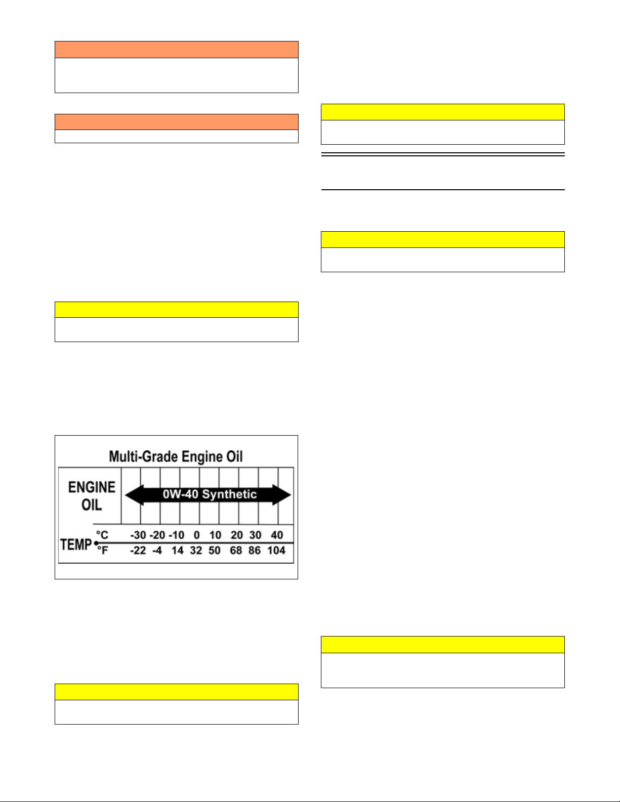
Engine Oil (recommended) ACX All Weather (Synthetic)
Front Differential Lubricant SAE-Approved 80W-90 Hypoid
Transaxle Lubricant Synthetic Transaxle Fluid with EP
Belt Width 38.4 mm
Brake Fluid DOT 4
Taillight/Brake Light LED
Headlight Halogen H13 with LED
Electric Starter Type Constant Mesh
COOLING SYSTEM
Cooling Fan 1 On 194° F (90° C)
Cooling Fan 1 Off 185° F (85° C)
Cooling Fan 2 On 203° F (95° C)
Cooling Fan 2 Off 194° F (90° C)
Thermostat Opening Temperature 156.2-163.4° F (69-73° C)
ELECTRICAL SYSTEM
Ignition Coil Resistance (primary)
(secondary)
1.40 ohm ± 15%
10,000 ohm ± 15%
Ignition Coil Primary Voltage Battery Voltage
Stator Coil Resistance 0.19 ohm ± 20%
Pickup Coil Resistance 495 ohm ± 20%
AC Magnetos Output 14 volts, 39 A @ 5000 RPM
Alternator Output 65 amps
Ignition Timing 8° BTDC @ 1500 RPM
Intake Air Temperature Sensor 315 ohm @ 176° F (80° C)
Coolant Temperature Sensor 5,740 ohm @32° F (0° C)
310-326 ohm @ 176° F (80° C)
183.6 ohm @ 212° F (100° C)
VALVES AND GUIDES
Valve Head Diameter (intake)
(exhaust)
30.90-31.10 mm
25.90-26.10 mm
Valve/Tappet Clearance (intake)
(cold engine) (max) (exhaust)
0.16 mm
0.22 mm
Valve Guide/Stem (intake)
Clearance (max) (exhaust)
0.08 mm
0.10 mm
Valve Guide Inside Diameter (max) 4.550 mm
Valve Head Thickness (min) 2.3 mm
Valve Seat Angle 45° +15’/+30’
Valve Spring Free Length (min) 37.59 mm
Valve Spring Tension @ 34.6 mm 112.30-129.30 N (25.25-29 lb)

3
Torque Specifications
CYLINDERS, PISTONS, AND RINGS
Piston/Cylinder Clearance
(max)
.035-.060 mm
0.120 mm
Cylinder Bore 80.000-80.010 mm
Piston Diameter 79.950-79.965 mm
Bore x Stroke 80.0 x 66.2 mm
Cylinder Trueness (max) 0.05 mm
Piston Ring End Gap Installed (Top)
(2nd)
(Oil)
.15-.25 mm
.30-.45 mm
.10-.35 mm
Piston Ring Side Clearance Installed (Top)
(2nd)
(Oil)
.030-.065 mm
.020-.055 mm
.040-.140 mm
Piston Ring Groove Width (1st/2nd)
(Oil)
1.202-1.204 mm
2.501-2.503 mm
Piston Ring Thickness (1st/2nd) 1.170-1.195 mm
Piston Pin Bore (max) 19.045 mm
Piston Pin Outside Diameter (min) 18.971 mm
CRANKSHAFT
Connecting Rod (small end diameter)
(big end diameter)
19.005-19.018 mm
41.00-41.018 mm
Crankshaft Runout (max) 0.05 mm
Crankshaft Thrust Clearance 0.05-0.25 mm
Torque (ft-lb) Tolerance
0-15 ±20%
16-39 ±15%
40+ ±10%
Part Part Bolted to Torque
ft-lb N-m
EXHAUST COMPONENTS
Manifold Engine 16 22
Muffler Transaxle Bracket 16 22
Spark Arrester Muffler 72 in-lb. 8
O2 Sensor Manifold 20 27
BRAKE COMPONENTS
Brake Disc Hub 16 22
Brake Hose Caliper 20 27
Brake Hose Master Cylinder 20 27
Brake Hose Frame 8 11
Master Cylinder Frame 25 34
Rear Caliper**** Bearing Housing 35 48
Front Caliper**** Knuckle 35 48
Remove Reservoir Frame 8 11
Front Brakeline Clip Upper A-Arm 6 8
Brake Pedal Frame 18 25
SUSPENSION COMPONENTS (Front)
A-Arm (Upper) Frame 75 102
A-Arm (Lower) Frame 75 102
A-Arm (Upper) Knuckle 75 102
A-Arm (Lower) Knuckle 75 102
Knuckle Tie Rod End 42 57
Shock Absorber**** Frame 75 102
Shock Absorber**** A-Arm 75 102
Knuckle Assembly** Axle 250 339
Sway Bar Mount Frame 42 57
Sway Bar Link A-Arm 35 48
SUSPENSION COMPONENTS (Rear)
Sway Bar Mount Frame 35 48
Sway Bar Sway Bar Link 35 48
Sway Bar Link Trailering Arm 35 48
Trailering Arm Frame 170 230
Bearing Housing Assembly Trailering Arm 35 48
Shock Trailering Arm 65 88
Shock Frame 65 88
Hub** Axle 250 339
Trailering Arm Rod End Trailering Arm 90 122

4
*w/Oil
**w/Red Loctite #271
***w/Green Loctite #270
****w/“Patch-Lock”
*****w/Anti-Seize
Torque Conversions
(ft-lb/N-m)
Drive Belt Break-In
Procedure
New drive belts require a break-in period of 25 miles.
During this period, drive the vehicle for 25 miles at 3/4
throttle or less while varying throttle position (but not
exceeding 40 mph). By varying throttle position, the
exposed cord on the side of a new belt will be condi-
tioned allowing the drive belt to gain its optimum flexi-
bility and will extend drive belt life.
Gasoline — Oil — Lubricant
FILLING GAS TANK
Since gasoline expands as its temperature rises, the gas tank
must be filled to its specified capacity only. Expansion room
must be maintained in the tank particularly if the tank is filled
with cold gasoline and then moved to a warm area.
Part Part Bolted to Torque
ft-lb N-m
STEERING COMPONENTS
Steering Rack Mount Bracket 20 27
Mount Bracket Frame 20 27
EPS Bracket EPS Unit 35 48
Lower Steering Shaft (Splined End) Steering Rack 35 48
Lower Steering Shaft (Adj. Yoke) Self 35 48
Lower Steering Shaft (Upper
Splined End)
EPS Unit 35 48
Upper Steering Shaft (Splined End) EPS Unit 20 27
Upper Steering Shaft (Adj. End) Self 35 48
Tilt Steering Sub Assembly Frame 20 27
Tilt Steering Shock Frame 8 11
Steering Shaft** Steering Wheel 25 34
SEAT BELT ASSEMBLY
Seat Belt Retractor Frame 60 82
Seat Belt Flange Frame 60 82
Seat Belt Buckle Frame 60 82
Seat Belt Rear ROPS 35 48
SHIFTER ASSEMBLY
Shift Knob Shift Lever 12 16
Shift Cable End Shift Lever 8 11
Shift Cable Threads Bracket/Transaxle 20 27
Shift Cable Bracket Transaxle 6 8
Shift Axle Shift Bracket 8 11
COOLING ASSEMBLY
Upper Radiator Bracket Frame 14 19
P-Clamp Frame 8 11
Overflow Bottle Support Bracket 8 11
Lower Radiator Bracket Frame 14 19
Radiator Fan Radiator Shroud 6 8
Shroud Assembly Radiator 8 11
CLUTCH ASSEMBLY
Drive Clutch Engine 60 81
Drive Clutch Fan Drive Clutch 60 in-lb. 7
Cam Arm Drive Clutch 50 in-lb. 6
Spider Stationary Sheave 250 339
Clutch Cover Movable Sheave 120 in-lb. 14
Torque Bracket Movable Sheave 120 in-lb. 14
Driven Clutch Transaxle 60 82
ENGINE/TRANSAXLE COMPONENTS
Engine Cradle Engine 35 48
Engine/Transaxle Mid Mount Cradle 35 48
Engine Mid Mount 65 88
Front Mount Engine Cradle 35 48
Isolator Front Mount 35 48
Isolator Frame/Rear Hanger 35 48
Transaxle Mid Mount 65 88
Mount Bracket Mid Mount 35 48
Transaxle Rear Mount 35 48
Isolator Rear Mount 35 48
Rear Hanger Frame 35 48
FRAME/ROPS COMPONENTS
Rear ROPS Assembly Frame 35 48
Lower Front Skid Frame 65 88
ROPS Frame 35 48
Front ROPS Rear ROPS 35 48
Lower Air Dam Lower Front Skid 8 11
Headlight Mount Frame 8 11
Shift Support Frame 20 27
Tire Hold Down Bracket Frame 20 27
Cargo Mount Frame 8 11
ft-lb N-m ft-lb N-m ft-lb N-m ft-lb N-m
11.4 26 35.4 51 69.4 76 103.4
22.7 27 36.7 52 70.7 77 104.7
34.1 28 38.1 53 72.1 78 106.1
45.4 29 39.4 54 73.4 79 107.4
56.8 30 40.8 55 74.8 80 108.8
68.2 31 42.2 56 76.2 81 110.2
79.5 32 43.5 57 77.5 82 111.5
810.9 33 44.9 58 78.9 83 112.9
912.2 34 46.2 59 80.2 84 114.2
10 13.6 35 47.6 60 81.6 85 115.6
11 15 36 49 61 83 86 117
12 16.3 37 50.3 62 84.3 87 118.3
13 17.7 38 51.7 63 85.7 88 119.7
14 19 39 53 64 87 89 121
15 20.4 40 54.4 65 88.4 90 122.4
16 21.8 41 55.8 66 89.8 91 123.8
17 23.1 42 57.1 67 91.1 92 125.1
18 24.5 43 58.5 68 92.5 93 126.5
19 25.8 44 59.8 69 93.8 94 127.8
20 27.2 45 61.2 70 95.2 95 129.2
21 28.6 46 62.6 71 96.6 96 130.6
22 29.9 47 63.9 72 97.9 97 131.9
23 31.3 48 65.3 73 99.3 98 133.3
24 32.6 49 66.6 74 100.6 99 134.6
25 34 50 68 75 102 100 136
! WARNING
Always fill the gas tank in a well-ventilated area. Never
add fuel to the gas tank near any open flames or with
the engine running. DO NOT SMOKE while filling the
gas tank.
Other manuals for XTR1000
1
This manual suits for next models
1
Table of contents
Other Tracker Off-Road Offroad Vehicle manuals