
No spare parts, tools, measuring equipment or any other
item shall be stored inside the high voltage enclosure. The
inside of the enclosure, terminals and cables shall be clean
and dry. If dust or water is present, the enclosure shall be
disconnected, earthed, cleaned and measures shall be
taken to prevent further ingress of dust or water. Measures
should be taken to prevent condensation inside the enclo-
sure.
An equipotential bonding wire should always be connected
to the enclosure. This is to ensure any fault current shall be
lead safely to earth, and that the enclosure in no way may
be dangerous to touch. The bonding wire should be of a
suitable cross section so that it may safely lead the fore-
seen fault-current to the ground.
Installation is to be performed by skilled personnel, fa-
miliar with high voltage installations and regulations,
“Ex” regulations, the ATEX Directive and/or IECEx
norms and standards. This includes but is not limited to:
IEC/EN 60079-0, IEC/EN 60079-7, IEC/EN 60079-14, com-
pany routines and national and international regulations.
Ferrules shall always be used on fine-stranded cables.
All clearance and creepage distances shall be according to
IEC/EN 60079-7 after installation.
Regardless of the regulations taking precedence in any in-
stallation, a dielectric strength test is highly recommended
after installation, before the equipment is put in service. In
most cases, this test will be mandatory.
Disposal/Recycling: When the apparatus is disposed of,
the respective national regulations shall be observed.
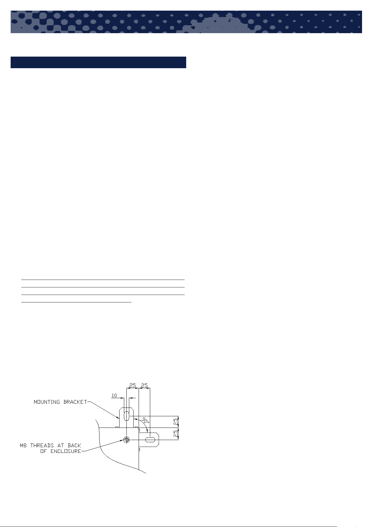
Mounting
The 1060 enclosure must be fastened by 4 pcs. of M10
bolts, or M8 bolt at holes in back of enclosure
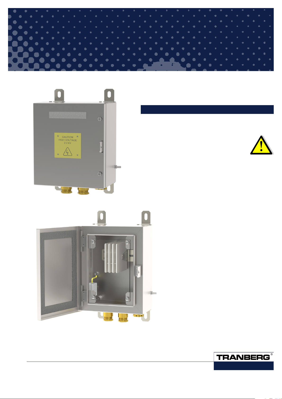
TEF 1060 HIGH VOLTAGE ENCLOSURE WITH A-BLOCK USER MANUAL
INSTALLATION
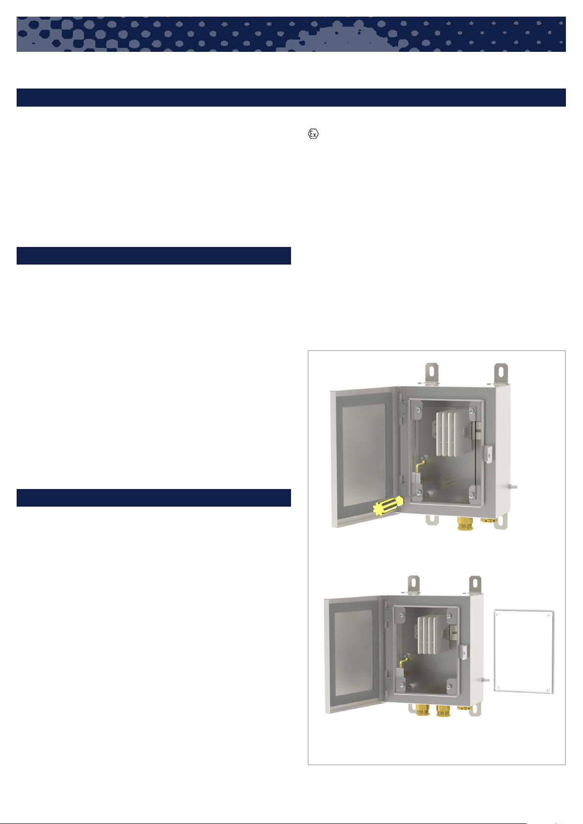
Connection
In order to maintain the mode of protection, the conductors
will have to be connected with special care. The insulation
must reach up to the terminal and the conductor must not
be damage. All screw and nut of the terminals, also those
remaining vacant, must be tighten down. For earth connec-
tion to stud or bar, cable shoes will have to be used.
Only certified cable entries and blinds may be used. Gland
has to be chosen according to cable diameter used.
To ensure the required minimum protection category glands
has to be tighten properly and unused holed has to be
closed with certified blinds according to hole diameter.
Close and lock door / lid. In case of bolt tight these firmly
with suitable tool by hand force. Over tightening may impair
the protection category.
Important
The panel must be mounted vertically to a wall or structure.
Make sure to use all four (and sometimes more) fixing
points, as the weight of the panel with components inside
may be considerable.
It is also very important that the rear of the panel stays level,
meaning that the fixing points on the structure must be in
the same plane. If one or more of the fixing points are out of
line, the panel is likely to be bent when fixed to the structure.
If the panel is bent it may result in several problems, such
as:
• Fault on IP degree of ingress protection, due to
certificate.
• Water intrusion (uneven pressure on door gaskets)
• Doors may not close completely or become difficult to
open
• The load on the fixing bolts may not be fully distributed
(excessive load on some points)
• Permanent deformation of the panel


 user manual")


