Trilithic Visionary HD/SD Overlay System Instruction sheet

Visionary HD/SD
Overlay System
Hardware Installation and
Configuration Manual


Visionary-HardwareInstallationandConfigurationManual
1
Trilithic Company Profile
Trilithicisaprivatelyheldmanufacturerfoundedin1986asanengineeringandassembly
companythatbuiltanddesignedcustomer-directedproducts for telecommunications, military,and
industrialcustomers. Fromitsmodestbeginningsasatwo-manengineeringteam,Trilithic grew
overtheyearsand broadened its offerings of RFandmicrowavecomponents by adding
broadbandsolutionstoits product line. This was accomplishedwiththeacquisition of
componentsmanufacturer Cir-Q-TelandinstrumentsmanufacturerTexscan.
Today,Trilithicisanindustryleader,providingtelecommunicationssolutionsformajorbroadband,
RFandmicrowavemarketsaroundtheworld. AsanISO 9000:2001 certified companywith over
40yearsof collective expertise in engineeringandcustom assembly,Trilithic is dedicated to
providingqualityproducts,servicesandcommunicationssolutionsthatexceedcustomer
expectations.
Trilithicis comprised of five majordivisions:
•Broadband Instruments and Systems
Offerstest,analysis,andqualitymanagementsolutionsforthemajor cable television
systemsworldwide.
•RF Microwave Components
Providescomponentsandcustomsubsystemsforcompanies specializing in cellular,
military, and other wireless applications.
•Emergency Alert Systems
Leadingsupplierofgovernment-mandatedemergencyalertsystemsusedbybroadcast
TV, cable TV, IPTV, DBS, and radio stations.
•XFTP
Offersaspecialtyline of field technical products for cableoperatorsand technicians, as
wellasalineofproductsforinstallingelectronicsinthehomeofthefuture.
•Network Services
Providesnetworkdatamanagementandsupportservices to safeguard and protect your
networkanddatabyemploying certified, experienced, and dedicated network engineers.

Visionary - Hardware Installation and Configuration Manual
2
Table of Contents
1. General Information..............................................................................................................5
UnpackingandInspection ......................................................................................................5
Claims for Damage in Shipment ............................................................................................5
HelpfulWebsite .....................................................................................................................6
WheretoGetTechnical Support.............................................................................................6
HowthisManualisOrganized................................................................................................7
ConventionsUsedinthisManual ...........................................................................................8
Precautions ...........................................................................................................................8
2. Understanding the Visionary...............................................................................................9
Introduction ............................................................................................................................9
WhatDoesthe Visionary HD/SD Overlay System Do?...........................................................9
Featuresand Capabilities ofthe Visionary System ..............................................................10
Custom EAS Messages.................................................................................................10
Logo Display..................................................................................................................10
HowtheVisionarySystemFunctionsinanEASActivation...................................................10
OverviewoftheVisionaryHD/SDOverlaySystem ...............................................................11
FrontPanelView............................................................................................................11
Rear Panel View ............................................................................................................12
RearPanel Details .........................................................................................................13
3. Installing and Wiring the Visionary ...................................................................................17
Overview .............................................................................................................................17
WiringRecommendations....................................................................................................17
EASyCASTandVisionaryIntegration(Sample) .............................................................18
4. Configuring the Visionary..................................................................................................19
Overview .............................................................................................................................19
ComputerSystemRequirements .........................................................................................19
InstallingtheConfigurationSoftware.....................................................................................19
ConfigurationProcedure......................................................................................................24
GeneralCommunicationConfiguration ...........................................................................24
VisionaryConfiguration ..................................................................................................26
ConfiguringMultiple,IndependentVisionarys..................................................................27
SystemTimeConfiguration.............................................................................................28
ConfigureStationIdentificationandTrigger Pages .........................................................29
AudioConfiguration........................................................................................................35
ImageConfiguration .......................................................................................................36
FontConfiguration..........................................................................................................37
UpgradingtheFirmware ......................................................................................................40
RemovingtheConfigurationSoftware ..................................................................................42

Visionary-HardwareInstallationandConfigurationManual
3
5. Specifications .....................................................................................................................42
TechnicalSpecifications.......................................................................................................43
Chassis..........................................................................................................................43
Serial Digital Video ........................................................................................................43
Audio .............................................................................................................................43
Character/GraphicsGeneration......................................................................................44
CommandandControl ...................................................................................................44
WarrantyInformation ............................................................................................................45

Visionary - Hardware Installation and Configuration Manual
4
THIS PAGE INTENTIONALLY LEFT BLANK

Visionary-HardwareInstallationandConfigurationManual
5
Chapter 1
1. General Information
Unpacking and Inspection
WhentheVisionaryHD/SDOverlaySystemarrives,immediatelyinspecttheshippingcontainer
andcontentsforvisible damage. Keep all packing materials untiltheequipment’s intended
performancecharacteristicshavebeen verified. If any of the equipmentisdamaged or fails to
operateproperlyduetotransportationdamage, immediately file a claim with the transportation
companyor, if insured separately,withtheinsurancecompany.
EachVisionarywillarriveinitsown shippingcontainer. The containerwill,ata minimum, include
thefollowingcomponents:
• 1CDwhichcontainsthe Windows-based configuration program
• 1CDwhich contains the Visionary Editorsoftware
• 1null-MODEM9-pinserial data cable
• 1AC power cord
• 1Ethernetcable
Claims for Damage in Shipment
Claimsforshipping damage should be directedto the shipping and/or freightdeliveryservice
used. Claimsshouldbemade within 7 days toinsureprompthandling of the claim.

Visionary - Hardware Installation and Configuration Manual
6
Helpful Website
Thefollowingwebsitecontainsgeneralinformationwhichmaybeofinterest:
http://www.trilithic.com
Trilithic’swebsitecontains product specifications and information, tips, release information,
marketinginformation,FrequentlyAsked Questions(FAQs), bulletins,andothertechnical
information. Thiswebsitecanbereferencedfor product updates.
Where to Get Technical Support
TrilithictechnicalsupportisavailableMondaythroughFridayfrom8:00AMto5:00PMEST.
CallersinNorthAmericacandial1-317-895-3600or 1-800-344-2412 (toll free). International
callersshoulddial 1-317-895-3600 or fax questionsto 1-317-895-3613. Youcan also e-mail
Forquickersupportresponsewhen calling or sending e-mail, please provide thefollowing
information:
• Your nameandyourcompanyname
• Thetechnicalpointofcontact(name,phonenumber,e-mail)
• TheserialnumberoftheVisionaryHD/SDOverlaySystem
• Adetaileddescriptionoftheproblemyouarehaving,includinganyerrororinformation
messages
BeforeanyTrilithic Visionarycanbereturnedforrepair,Trilithic will issue a return material
authorization(RMA)number. NORETURNEDEQUIPMENTWILLBEACCEPTEDWHICH
DOESNOTHAVEAN RMANUMBERPROMINENTLYDISPLAYEDONTHEOUTSIDE
SHIPPINGCARTONANDONTHE SHIPPING LABEL. Acompleteandfulldescription,inwriting,
regardingtheserviceissues with the equipment must be suppliedinsidetheshipping container
witheachpieceofequipmentforwhichanRMAnumber has been issued.
Hardwareorsoftware modificationsandchanges may occuratany
timeduringproduction,shipping,and/or duringtheequipment’slife
span. Thesechanges mayoccurorbeimplemented byTrilithic,
Inc.withoutpriorwrittennotice orwarning.

Visionary-HardwareInstallationandConfigurationManual
7
How this Manual is Organized
ThisinstallationmanualaddresseshardwareinstallationconcernsfortheVisionaryHD/SD
OverlaySystem.
Thismanualisdividedintothefollowingchapters:
• Chapter1,“GeneralInformation,”providesTrilithiccontactinformationanddescribeshow
thisinstallationmanualisstructured.
• Chapter2,“UnderstandingtheVisionary,” introduces the VisionaryHD/SDOverlaySystem
anddescribes what it does. The chapter discusses thepractical application of the
VisionaryandexplainstheVisionary’sindictorsandconnectionterminals.
• Chapter3,“InstallingandWiringtheVisionary,” describes the steps to installandconnect
theVisionary.
• Chapter4,“Configuringthe Visionary,”describesthe procedure to configure the Visionary,
usingtheprovidedconfigurationsoftware.
• Chapter5,“Specifications,” outlinesthetechnicalspecifications of the Visionary.

Visionary - Hardware Installation and Configuration Manual
8
Conventions Used in this Manual
Thismanualhasseveralstandardconventions for presentinginformation:
•Connections,menus,menuoptions,anduser-enteredtextandcommandsappearinbold.
• Section names, web and e-mail addresses appear in italics.
A NOTE is information that will be of assistance to you related
to the current step or procedure.
A CAUTION alerts you to any condition that could cause a
mechanical failure or potential loss of data.
A WARNING alerts you to any condition that could cause
personal injury.
Precautions
Do not use the Visionary HD/SD Overlay System in any manner
not recommended by the manufacturer.

Visionary-HardwareInstallationandConfigurationManual
9
Chapter 2
2. Understanding the Visionary
What Does the Visionary HD/SD Overlay System Do?
TheVisionaryHD/SDOverlaySystemenablesbroadcasterstopresentemergencyalert
messages,graphics, and station identificationlogos on digital broadcasts. The Visionary works
with Trilithic’s EASyCAST encoder/decoder to provide EAS messaging and logos for HD-SDI
and SD-SDI broadcast programming (1080i, 720p, and 480i), including embedded audio and six
channelsofAES-EBUaudio.
TheVisionaryreceives EAS alerts fromthe encoder/decoder and places themon a broadcast
channelasa message crawl, withEAS audio. The Visionary also allowsbroadcasters to display
stationlogos and other event-specific graphicswith broadcasted EAS message alerts.
TheVisionarycan display non-EAS messages as acrawl,static text, image, full-page graphic,or
acombination of text and images. If a broadcaster needs to displaymaintenance messages –
evenfromaremote location – the message can be presentedonthebroadcast channel using the
Visionarysystem. Non-EASmessaging is generally handled usinga PC and the VisionaryEditor
software.
TheVisionaryconnects to the EASyCASTencoder/decoderviaan Ethernet connection. Asingle
encoder/decodercancommunicatewithmultiple Visionary devices on a network. Broadcasters
canplaceaVisionaryon each program channel and only havetomaintainand program a single
EASyCAST encoder/decoder to distribute EAS messages.
Introduction
ThissectionincludesanoverviewanddescriptionoftheVisionaryHD/SDOverlaySystem,
includingfrontandrearpanelcontrols,connectors, and displays. Visitwww.trilithic.comtoviewor
downloadupdates,manuals,andapplicationnotesforTrilithic EAS products.
TheVisionaryisavailable in two formats: high-definition (HD) and standarddefinition(SD). The
HDversionsupportsbothhighandstandarddefinitionvideo. Thefollowing part numbers are
uniquetoeachoftheVisionarys:
Visionary HD SDI (high-definition) - P/N 2011186002
Visionary SD SDI (standard-definition) - P/N 2011186001

Visionary - Hardware Installation and Configuration Manual
10
Features and Capabilities of the Visionary System
Inaddition to receipt and redistribution of EAS messaging from the EASyCASTencoder/decoder,
theVisionarygivesstationoperatorsthe ability to create custom messages. Through the
VisionaryEditor software, custom messages andgraphics can be inserted intothe broadcast
display.
Custom EAS Messages
TheEditorsoftwareallowsthecreationof custom messaging in the form of static text,crawl
text,andcustomlogoinsertion. Statictextcanbeplacedanywhereonthescreen,andall
movementparametersfortextcrawlscanbecontrolled. Customizabletextpropertiesinclude
position,font,size,color,backgroundcolor,transparency, crawl speed, and the number of
timesthe crawl is repeated.
Logo Display
Multiplelogos/imagescanbeplacedonthescreen,withindependentcontroloverlocation,
transparency,andfadein/outforeachgraphic.
How the Visionary System Functions in an EAS Activation
Duringnormalbroadcasting,videoisrouted through the VisionarySDIinputandoutput. Audiois
routedthroughtheVisionaryembeddedintheSDI,orthrough the baseband audio orAES/EBU
inputsandoutputs.
During EAS activations, the EASyCAST encoder/decoder sends EAS crawl and custom image
informationtothe Visionary over the Ethernetinterface. EASaudio is supplied to the Visionary
basebandaudioinputs,orsentoverEthernetas an audio file (.wav).
Usingcontactclosureinputs,automationandcommercialinsertionequipmentcanbeusedtohold
offEASmessagesduring commercials or other importantprogramming. TheVisionarywill hold
allmessagesin queue until automation equipmentoran operator provides a trigger torelease
queuedmessages. Operatorscanalso trigger the Visionary using Ethernetcommandsfroma
PC-based software application.

Visionary-HardwareInstallationandConfigurationManual
11
Overview of the Visionary HD/SD Overlay System
Front Panel View
21
1. Power LED -Indicates whether the Visionary is powered onor off.
2. Status LED -Indicates whether the Visionary control firmware has been initializedand
isrunning. ThestatusLEDwillnotilluminateuntil the firmware has beenfullyinitialized.
Afterthefirmwarehas been initialized, the LED will blinkonandoff.
Visionary - Hardware Installation and Configuration Manual
12
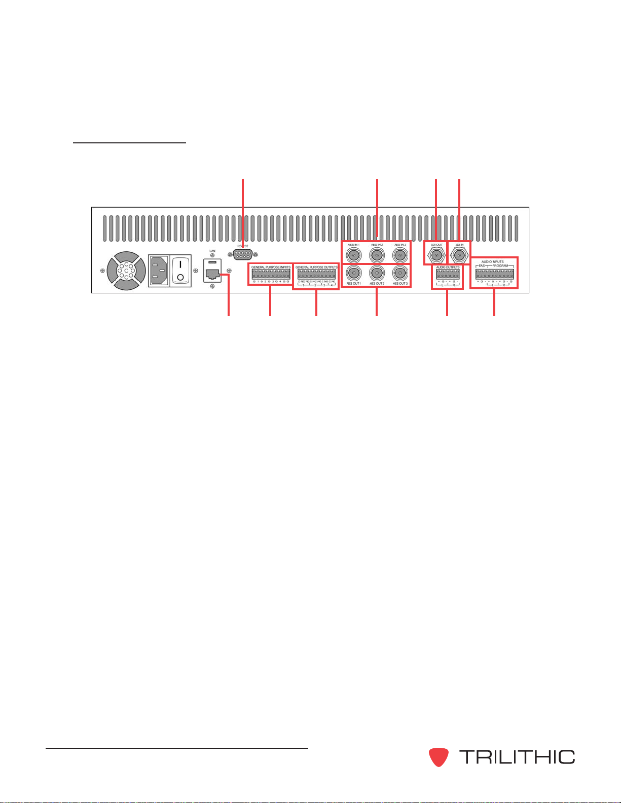
Rear Panel View
1. Ethernet port (RJ-45) - Ethernetportusedforconfiguration, control, and audio
deliveryfromthe EASyCASTEASencoder/decoderor a host computer.
2. COM 1 (RS-232) - Connectstoa host computer during initial configurationofthe
VisionaryIPaddress.
3. General purpose inputs - Contactclosureinputsallowsexternal devices – such as
commercialinsertionequipment– or operators to control messageactivation.
4. General purpose outputs - Usedfor distribution/routing equipment that requiresa
contactclosureforactivation. Alsousedtocontrolindicatorlampsoralarms for studio
personnel.
5. AES audio inputs - Normalprogram audio is routed to these inputs forreplacement
duringEASactivations.
6. AES audio outputs - Theseoutputs provide normal programaudio except during EAS
activations,atwhichtimetheycontainEAS audio.
7. SDI output - Thisoutputprovides normal program video (withembeddedaudio)
exceptduringoverlayoperations, at which time it can provideprogramvideowith a
graphicandtextoverlayandembeddedaudioreplacement.
8. SDI input - Inputfornormalprogramvideo with or without embedded audio.
9. Audio output - Thisoutputprovidesnormal program audio except duringEAS
activations,atwhich time it contains EASaudio.
10.Audio inputs - Baseband inputs for program audio, and EAS audio from the
EASyCASTencoder/decoder.
25
3 4 6
7
910
8
1

Visionary-HardwareInstallationandConfigurationManual
13
Rear Panel Details
Ethernet port (RJ-45 connection): Usedforconfiguration, control, and upgrading the
Visionary’sfirmware. EASmessaging is sent totheVisionary via the Ethernetport.
COM 1 (RS-232 connection): 9-pin RS-232C DTE interface used for initial configuration, via
a9-pinNULL-MODEM cable.
Pin 1: Notused
Pin 2: Receivedata*
Pin 3: Transmitdata*
Pin 4: Dataterminalready
Pin 5: Signalground*
Pin 6: Data set ready
Pin 7: Requesttosend
Pin 8: Clear to send
Pin 9: Ringindicator
*Requiredsignal
General purpose inputs: ContactclosureinputsforcontrollingtheoutputoftheVisionary;
includingEASmessagetiming,activation,orhold-offcontrol.
(G) - Groundforgeneralpurposeinput1
(1) -Abort message in progress: Whenclosed,causes the message currently being
playedtostopand the next message inqueuetobe played.
(G) - Groundforgeneralpurposeinput2
(2) - Trigger EAS message: Starts playback of the first EAS message in the message
queue.
(G) - Groundforgeneralpurposeinput3
(3) - Trigger normal message: If no EAS messages are in the queue, causes the first
normal-prioritymessageto be displayed. When the Visionaryis programmed with a
recurringGPI-controlledmessage,themessagewillbedisplayed while this contact is
closed,andremovedwhenthiscontactis opened.

Visionary - Hardware Installation and Configuration Manual
14
(G) - Groundforgeneralpurposeinput4
(4) - Hold-off: Prevents EAS or user-generated messages from being displayed or played
backuntilthe contact is opened. Once the hold-offisreleased (opened), closing it
againwillnot stop the message playback.
(G) - Unusedgroundedpin
(G) - Unusedgroundedpin
General purpose outputs: Usedascontactclosuresfor distribution/routing equipment that
requiresacontact closure for activation, or foroperatoralarms during EAS operations.
Contact closure 1, message queued: This contact closure is closed when a message
hasbeenreceived, but is waiting for anactivationtrigger.
(C) Commoncontact
(NC) Normallyclosedcontact
(NO) Normallyopencontact
Contact closure 2, message active: This contact closure is closed whenever a video
overlayoraudio playback is in progress. Itcan be used to controlindicator lights or
externalswitching/routingequipment.
(C) Commoncontact
(NC) Normallyclosedcontact
(NO) Normallyopencontact
Contact closure 3, audio active: This contact closure is closed whenever audio
playbackisinprogress. Itcan be used to control indicator lightsorexternalswitching/
routingequipment.
(C) Commoncontact
(NO) Normallyopencontact
Contact closure 4, programmable: This contact will close if a message is being played
inwhichtheuser-programmablecontact-closureoptionisturned on.
(C) Commoncontact
(NO) Normallyopencontact

Visionary-HardwareInstallationandConfigurationManual
15
AES/EBUAudio: Providesa synchronizedAES/EBUaudio pathfor in-line
replacementofprogramming audio during EAS operations. Ifan input is provided
(fromastationsource),theoutputsampleratewillbeequaltothe input sample rate. If
noinputisprovided, the output sample rate will be 48KHz.
AES/EBU input: 110 ΩΩ
ΩΩ
ΩXLR female
Pin 1: Ground/drain
Pin 2: Balanced(+)
Pin 3: Balanced(-)
AES/EBU output: 110 ΩΩ
ΩΩ
ΩXLR male
Pin 1: Ground/drain
Pin 2: Balanced(+)
Pin 3: Balanced(-)
SDI OUT: 75 ΩBNC serial digital interface output compliant with SMPTE 259M, 292M, and
274Mstandards. Supports embedded audio, audioreplacement, and video overlay. SDI
OUTissynchronizedwiththeSDIIN signal. If the SDIINsignalislost,SDIOUTcontinuesto
providevideoatthe last sampled input rate. On power failure,theSDI IN signal is routed to
theSDIOUTconnection using a fail-safe relay.
SDI IN: 75 ΩBNC serial digital interface input compliant with SMPTE 259M, 292M, and
274Mstandards.
Audio outputs: 600 Ωbalanced audio stereo pair provides the program audio input signal
duringnormaloperation. DuringEASorauxiliary audio operations the Visionary internal
audioissuppliedto these outputs.
Audio inputs (program): 600 Ωbalanced audio stereo pair routed to the audio outputs
throughrelaysduringnormaloperation. Duringaudioreplacementoperationstheprogram
audioinputsaredisconnectedfromtheaudiooutputs.
Audio inputs (EAS): 600Ωbalancedaudio input is normally connectedtoan audio output
from the EASyCAST EAS encoder/decoder. It provides a means to deliver EAS audio to the
internalcircuitryoftheVisionaryforaudioreplacementoperations.

Visionary - Hardware Installation and Configuration Manual
16
THIS PAGE INTENTIONALLY LEFT BLANK

Visionary-HardwareInstallationandConfigurationManual
17
Overview
TypicalinstallationoftheVisionary involves routingthenormalstationaudioandvideothroughthe
Visionary, sothatthey can be modified orreplaced during message operations. In addition,the
Visionarymustbe connected and configured fornetworkoperation and the EASyCAST EAS
encoder/decodermustbeconfiguredtocommunicatewiththeVisionary.
• Thestation’s final SDI video signal should be routed totheSDIINonthe Visionary,andthe
SDIOUToftheVisionary connected to complete the signal path. Typically, the Visionary
willbeinsertedjustpriortotheMPEGencoderorchannelmultiplexer.
• Thestation’saudioisinterceptedand routed through the Visionary audio inputs and
outputs. UptosixAES/EBU channels, two baseband balanced audio channels, andeight
channelsofembedded audio can be processed bytheVisionary. Typicallythe audio input
totheMPEGencoderisreroutedthroughthe Visionary.
• TheVisionaryEthernetportisconnectedto a switch or router on the station’s network. The
Visionarymust beconfiguredforavalid IPaddress,subnet,andgateway. Routers and
firewallsmayneedtobeconfiguredto allow communications between the EASyCAST
EASencoder, the Visionary,andany PCs used for configuration or controloverthe
Visionary.
• Ifpossible,one of the audio outputsfromthe EASyCAST EAS encoder shouldbe
connectedtothe EAS audio input on theVisionary. This reducesnetworktrafficand
increasesaudioqualityduringnational EAS alerts.
• Ifused,theVisionaryconfigurationsoftware,editingsoftware, and EAS Console
applicationshouldbeinstalledonaPCwithIPconnectivitytotheVisionary. Thedefault
TCP/UDPportsused by the Visionary are 59901(configurationand control), 59902
(streamingaudio),21 (FTP audio), and 123(SNTP).
• InitialIPconfigurationisperformed using a Windows PC with an RS-232connectiontothe
Visionary,oroveranEthernetconnectionifthe PC can be re-configured for an IPwithinthe
10.1.65subnet(thedefaultIPoftheVisionaryis10.1.65.80).
Wiring Recommendations
Shieldedaudiowirefor all contact closures and audio connections
• Shielded RS-232 cables
• Shielded(coaxial) SDI video cables
• Category5or 6 Ethernet cable
Chapter 3
3. Installing and Wiring the Visionary

Visionary - Hardware Installation and Configuration Manual
18
EASyCAST and Visionary Integration (Sample)
Table of contents


