Trinity Amps 18 Watt User manual

The 18 Watt Amp
Builder's Guide
April 2018, Version 3.0
For the sole personal use of Trinity Amps Customers.
Parts © Trinity Amps 2005 - 2017
www.trinityamps.com

Trinity Amps 18 Watt uilder’s Guide. Version 3.0
Page - 2

TableofContents
Table of Contents .................................................................................................................................................. 3
Thank ou! ............................................................................................................................................................ 5
Introduction .......................................................................................................................................................... 7
Acknowledgements ............................................................................................................................................... 7
WARNING............................................................................................................................................................ 8
Version Control ..................................................................................................................................................... 9
Fender and Marshall Tone controls ..................................................................................................................................................... 13
VOX Tone controls ................................................................................................................................................................................ 17
Distortion .................................................................................................................................................................................................. 19
General Amplifier Operation ................................................................................................................................................................ 21
Some DO NOTS ..................................................................................................................................................................................... 21
Some DOs ................................................................................................................................................................................................ 21
Introduction to Vacuum Tubes and Common Terms ......................................................................................... 23
Input Jack Theory ............................................................................................................................................... 26
Building an Amp ................................................................................................................................................. 27
Introduction .............................................................................................................................................................................................. 27
Switches and wire .................................................................................................................................................................................... 27
Physical layout .......................................................................................................................................................................................... 27
Grounding ................................................................................................................................................................................................. 27
Insulated jacks .......................................................................................................................................................................................... 28
Minimizing transformer interference ................................................................................................................................................... 28
Wiring ........................................................................................................................................................................................................ 28
Assembling the amp ............................................................................................................................................ 28
efore You egin .................................................................................................................................................................................... 28
Tools .......................................................................................................................................................................................................... 28
Soldering .................................................................................................................................................................................................... 29
Tube Pin Numbering .............................................................................................................................................................................. 29
Tube Designations .................................................................................................................................................................................. 30
Grounding Scheme ........................................................................................................................................................................ 31
Assembly Steps Summary .................................................................................................................................... 33
1. Install the Hardware ..................................................................................................................................................................... 34
Tube Sockets ................................................................................................................................................................................... 36
Can Capacitor ................................................................................................................................................................................. 36
Grommets ........................................................................................................................................................................................ 36
Front Panel ...................................................................................................................................................................................... 36
Terminal Strips ............................................................................................................................................................................... 36
Ground Lugs ................................................................................................................................................................................... 37
Impedance Switch .......................................................................................................................................................................... 37
Output Jacks .................................................................................................................................................................................... 37
IEC Mains Socket .......................................................................................................................................................................... 37
Fuse Holder ..................................................................................................................................................................................... 37
2. Heater Wiring ................................................................................................................................................................................ 38
Heater Wires.................................................................................................................................................................................... 38
3. Install Transformers ..................................................................................................................................................................... 39
4. Wire the Power Supply ................................................................................................................................................................ 39
120V MAINS .................................................................................................................................................................................. 42
220-240V MAINS .......................................................................................................................................................................... 43
RECTIFIER WIRING ................................................................................................................................................................. 44
HV WIRING .................................................................................................................................................................................. 44
Test the Power Supply .................................................................................................................................................................. 46
5. Assemble the Turret oard ........................................................................................................................................................ 47
Install Components on Turret oard ........................................................................................................................................ 47
Install the Turret oard ................................................................................................................................................................ 52
6. Connecting the Turret oard ..................................................................................................................................................... 53
Tube Sockets ................................................................................................................................................................................... 53
Socket Mounted Resistors ............................................................................................................................................................ 55
Phase Inverter Socket .................................................................................................................................................................... 55
TM Grid Stopper......................................................................................................................................................................... 55
Power Tube Wiring and Screen Resistor ................................................................................................................................... 56
v6 EL84 Power Tube Wiring – Grid Stopper, Screen Resistor ........................................................................................... 56

Trinity Amps 18 Watt uilder’s Guide. Version 3.0
Page - 4
v6 6V6 Power Tube Wiring – Grid Stopper Resistor ........................................................................................................... 57
v6 Power Tube Cathode Switch .................................................................................................................................................. 58
Connecting Controls - Potentiometers ...................................................................................................................................... 61
7. Output – Transformer, Impedance Switch, Jacks ................................................................................................................. 62
Connecting the Impedance Selector ........................................................................................................................................... 63
Output Jacks .................................................................................................................................................................................... 64
8. Input - Jacks and Input Grid Resistors .................................................................................................................................... 65
Input Grid Resistors ...................................................................................................................................................................... 65
Input Jacks ....................................................................................................................................................................................... 65
Combo Chassis Cliff Jack Wiring ............................................................................................................................................... 67
Preparing Co-Axial Wire ............................................................................................................................................................... 67
Final checkout ..................................................................................................................................................... 68
Power Up ............................................................................................................................................................. 69
Working Inside A Tube Amplifier Safely ........................................................................................................................................... 69
Unplug .............................................................................................................................................................................................. 69
Sit ....................................................................................................................................................................................................... 69
Drain ................................................................................................................................................................................................. 69
Test.................................................................................................................................................................................................... 69
Close ................................................................................................................................................................................................. 69
Making a Voltage Measurement ........................................................................................................................................................... 70
Trinity 18 TMB / sIII / Plexi / v6 Voltage Chart ............................................................................................... 72
Read this Information Carefully .................................................................................................................................................. 73
Troubleshooting .................................................................................................................................................. 73
Hum ........................................................................................................................................................................................................... 73
Volume Test ............................................................................................................................................................................................. 73
Faulty tube ................................................................................................................................................................................................ 74
Severely unmatched output tubes in a push pull amplifier ............................................................................................................. 74
Faulty power supply filter caps ............................................................................................................................................................. 74
Faulty bias supply in fixed bias amplifiers .......................................................................................................................................... 75
Unbalanced or not-ground-referenced filament winding ................................................................................................................ 75
Defective input jack ................................................................................................................................................................................ 75
Poor AC grounding ................................................................................................................................................................................. 75
Induced hum ............................................................................................................................................................................................ 75
Poor internal wire routing ...................................................................................................................................................................... 75
Poor AC Chassis Ground at Power Transformer ............................................................................................................................. 76
Defective internal grounding................................................................................................................................................................. 76
Hiss ............................................................................................................................................................................................................. 76
Metal Film Resistor Substitutions ........................................................................................................................................................ 76
Squealing/Feedback ................................................................................................................................................................................ 76
Radio Interference ................................................................................................................................................................................... 77
Scratchy Sounds on Potentiometer(s) ................................................................................................................................................. 78
Amp uzz or Rattle When Installed in Cabinet ................................................................................................................................ 78
18 Watt Tone Tweaking ....................................................................................................................................... 81
More Tips for fine tuning your amp .................................................................................................................................................... 86
Tube Substitutions .............................................................................................................................................. 87
How to read Resistor Color Codes ...................................................................................................................... 88
First the code .................................................................................................................................................................................. 88
How to read the Color Code ....................................................................................................................................................... 88
How to Read Capacitor Codes ............................................................................................................................ 89
FAQ 91
Cliff Jacks Explained ........................................................................................................................................... 94
18 Watt Bill of Material (BOM) ............................................................................................................................ 95
Trinity Amps Schematics and Layouts ............................................................................................................... 101

Thank ou!
Thank you for purchasing your kit from Trinity Amps. We truly hope that you enjoy building it. If
you have any questions please do not hesitate to contact us.
We are always looking for feedback form our Customers on our products. We have checked the
build instructions over thoroughly and are confident in our product. However, mistakes do happen
so our advice is that as you connect each wire and part according to the layout, cross-check against
the schematic. If you find any inconsistencies, or have any concerns, please let us know. Do not
hesitate to contact us! We want this build to be successful for you and for Trinity Amps!
Please check over your parts carefully and the ill of Materials and notify us of anything that does
not seem correct.
We’re confident that you will like our product and our support and when you’re completed, we’d
appreciate your comments posted on any of the internet forums such as thegearpage.net,
18watt.com, AX84.com or trinityamps.com. You will find some extra business cards in the package.
Please keep one and pass the rest around.
We know you have a choice in suppliers and we do appreciate your business.
Have Fun!!
Cheers,
Stephen Cohrs,
Trinity Amps
Web site: www.trinityamps.com
email: [email protected]


Introduction
This guide has been prepared for builders of Trinity Amps Kits. It is always being improved and we
would appreciate your feedback and comments to: stephen@trinityamps.com
Accordingly, content and specifications are subject to change without notice.
We do try to make it as accurate as possible, but it is sometimes hard to keep up with the changes.
Therefore, if you do find an error, please let us know about it and we will correct it. Suggestions are
welcome so if you have one, please get in touch with us.
Sources of help.
Forums: Please use the various forums to get help. They are an excellent resource and can be found
at trinityamps.com, AX84.com, the Gear Page etc..
Color assembly pictures and the latest drawings, tips, techniques are all in the Trinity Amps Forum,
in the Resources Forum.
Email: We can’t help with every problem but if you can not get your problem resolved, email us and
we’ll do our best to help.
Phone Call: If your problem can’t be solved, email for a phone appointment.
Acknowledgements
Much of the content in this document is original. Rather than reinvent content, some parts are
based on content from other excellent sources and are hereby acknowledged.
R.G. Keen’s site
www.geofex.com
- Tube Amp FAQ, Tube Amp Debugging
AX84.com site
www.AX84.com
- Gary Anwyl's P1 construction guide version 1.0
GM Arts website
http://users.chariot.net.au/~gmarts/index.html
- Guitar Amp asics
www.18watt.com
- website for various content and diagrams – Richie TM
Aron from diystompboxes.com
Parts © Trinity Amps. No part of this document may be copied or reprinted without written
permission of Trinity Amps or contributing authors listed above.

Trinity Amps 18 Watt uilder’s Guide. Version 3.0
Page - 8
WARNING
Please Read this Information Carefully
The projects described in these pages utilize POTENTIALL FATAL HIGH VOLTAGES. If
you are in any way unfamiliar with high voltage circuits or are uncomfortable working around high
voltages, PLEASE DO NOT RISK OUR LIFE B BUILDING THEM. Seek help from a
competent technician before building any unfamiliar electronics circuit. While efforts are made to
ensure accuracy of these circuits, no guarantee is provided, of any kind!
USE AT YOUR OWN RISK: TRINITY AMPS EXPRESSLY DISCLAIMS ALL LIA ILITY FOR
INJURY OR PROPERTY DAMAGE RESULTING FROM THIS INFORMATION! ALL
INFORMATION IS PROVIDED 'AS-IS' AND WITHOUT WARRANTY OF ANY KIND.
REMEM ER: NEVER OPERATE YOUR AMP WITHOUT A LOAD. YOU WILL RUIN
YOUR OUTPUT TRASNFORMER!

Trinity Amps 18 Watt uilder’s Guide. Version 3.0
Page - 9
Version Control
Version Date Change
2.0 25 Oct 12 New issue for New board & layout
27 Dec 12 Updated OM for Plexi Mk. II
12 Jan 13 Updated v6 OM
26 May 13 Added note on Switchcraft output jacks, and correctly named the Plexi MkII
board layout picture.
15Aug13 Updated OM for 22 & 20 ga. solid wire
2.1 28Oct13 Updated OM with notes
2.2 11Feb14 Updated board pictures and OM
2.3 29Jun14 Changed method of connecting leads to turret board. Added ROHS Notes;
OM Updated for v6 items
2.4 12Jan15 Clarification made about when to measure voltages.
2.5 27Jan15 OM Updated for Plexi MkII; added input jack theory
2.6 23Feb15 EF86 Pin out diagram changed
2.7 23Dec15 Impedance switch updated
2.8 14apr16 OM update with Impedance switch and knob
2.9 24Sep16 Updated v6 layout to piggy-back output tube bias design
2.92 2Mar17 Updated OM to reflect correct voltages
3.0 26Apr18 Updated new Power Transformer Primary wiring.

Trinity Amps 18 Watt uilder’s Guide. Version 3.0
Page - 10

Trinity Amps 18 Watt uilder’s Guide. Version 3.0
Page - 11
Guitar Amplifier Basics
Electric guitarists can be fairly criticized for their reluctance to change to new ideas and technologies; however,
there is no doubt that a classic 1950’s guitar and tube amplifier in good condition still sounds great in modern
recordings. This is a testament to good design from the start. What has improved today is consistency, and
the cost benefits of production line manufacturing. This is offset by the rarity of good guitar wood (it makes a
huge difference, even on an electric guitar), increased labour costs for both guitars and amplification
equipment, and the availability of good and consistent quality tubes.
There is also an element of nostalgia, with memories of many of the great players of years gone by, and the
desire to use the same types of instruments and equipment to recapture the magic. Vintage instruments and
equipment have also become valuable collectors items (some with very inflated prices) which adds further to
the desirability of older tools of the trade. There has been a recent trend by many companies to re-market
their original instruments and equipment; new guitars can even be bought now ‘pre-aged’!
This desire for vintage equipment is also related to guitarists’ reluctance to part with tube amplification, and
there are many reasons why tube and solid state amplifiers behave differently. Quite simply, if players prefer
the sound of tubes, they will continue to buy and use them. elow are some fundamentals.

Input Impedance
Typically 1M, 500K minimum (humbucking pickup guitars have volume pots up to
500K, single coil pickup guitars typically of 250K).
Tone Controls
Magnetic guitar pickups are inductive, and require compensation, although this
opportunity is also used for tone enhancement, not just correction. Without compensation, they have a
strong low middle emphasis and little high frequency response - overall a very muddy and muffled
sound. This is why typical hi-fi axandall treble & bass controls are unsuitable.
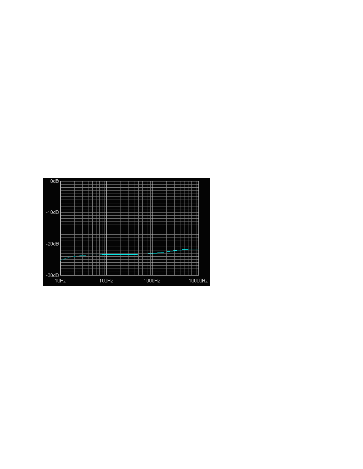
To hear the natural sound of a pickup, use a typical guitar amp with the middle set to full, and bass and treble
on 0. This is actually sets a flat response in the amp (see below). Expect to hear a muffled and muddy
sound. And that's the whole point of these tone controls providing compensation for the natural sound of a
pickup - the middle control simply boosts the pickup's normal ‘middley’ sound. The treble and bass controls
do the opposite - they boost higher and lower frequency levels, leaving a notch in-between for middle cut (see
the Fender/Marshall comparison below). So with typical settings of a bit of bass, middle and treble, the
overall tone equalization complements the natural pickup sound for a balanced response of lows, mids and
highs.
Full middle boost with no bass or treble actually gives a near-flat frequency response, allowing you to hear the
natural sound of your pickups.
Fender and Marshall Tone controls
Here are circuit diagrams of typical Fender and Marshall tone controls. They both meet the criteria of
compensating for pickups' low-middle emphasis, as well as providing a useful range of tone adjustment.

Trinity Amps 18 Watt uilder’s Guide. Version 3.0
Page - 14
The Fender and Marshall circuits are each tailored to suit their own styles, which are quite
different. Although a generalization, Fender's market and consequently the power output stage are geared
towards provided clean and chunky tones at clean and early-overdrive levels. Marshall amps are best at low-
middley and crunchy rock tones, played at medium to high overdrive levels.
Here is a simple comparison of Marshall and Fender response with what might loosely be called 'typical
settings' of ass on 3, Middle on 4, and Treble on 6. The most obvious difference is that the Marshall lets
more level through, and their tone controls have less range of adjustment. The higher level means that by
using the same number of preamp tube stages, a Marshall can overdrive the output stage more.
earing in mind that typical 6-string guitar notes don't go below 80Hz, and typical guitar speakers cut above
about 5KHz, these responses are similar. oth have a middle dip that is primarily compensation for typical
pickups' middle emphasis, rather than an obvious dip in middle response. The Marshall circuit has this cut
about an octave higher than the Fender, leaving the low mids and bass intact for that full Marshall
sound. On the other hand, Fender's tone controls allow high-mids to pass with the treble response, and add
little bass boost for the sparkling and tight sounds they're famous for.
Trinity Amps 18 Watt uilder’s Guide. Version 3.0
Page - 15
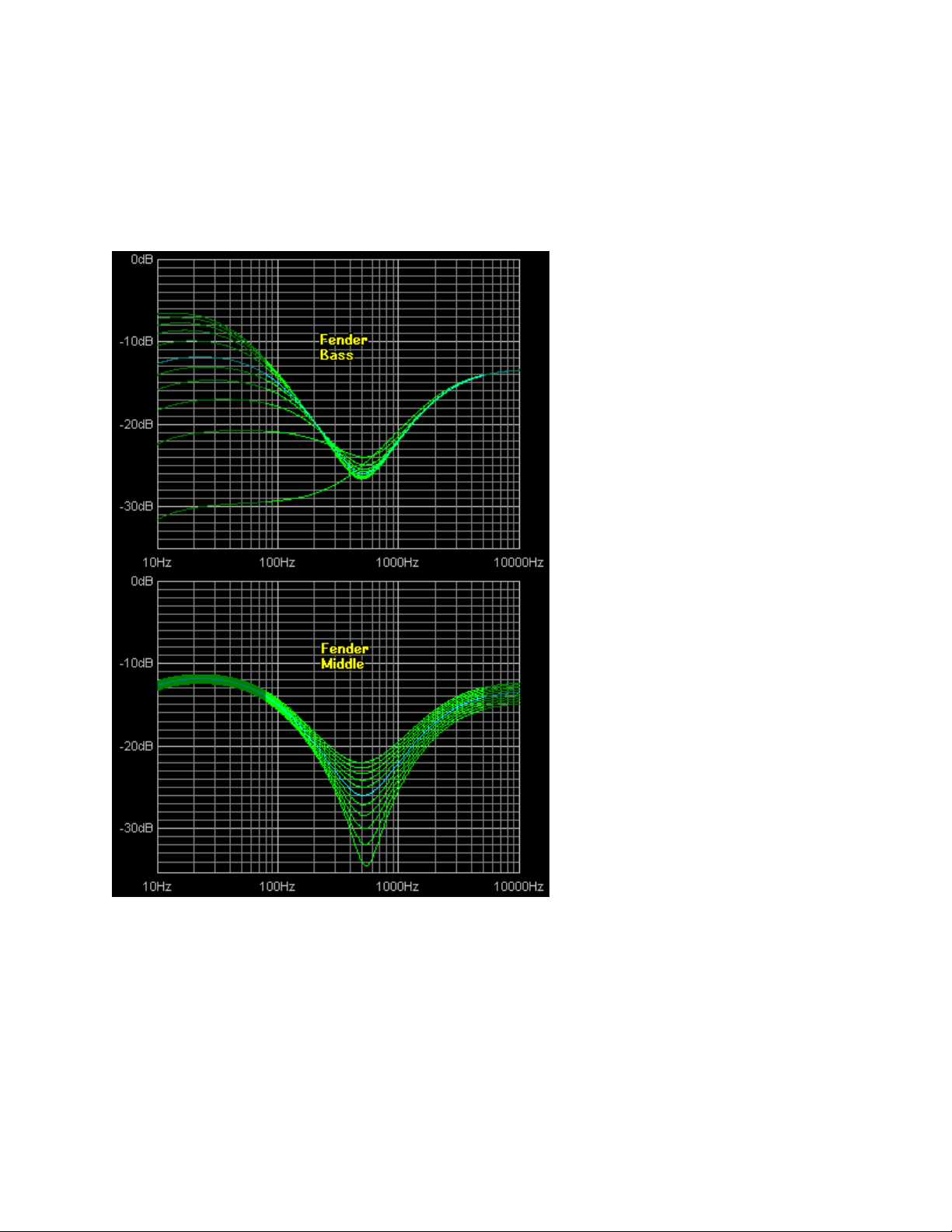
Here are charts each of the Fender controls. In all cases, the other two controls are left at 5. For example,
the treble chart shows the effect of varying Treble from 0 to 10, with ass and Middle both at 5. Notice that
all controls have a wide range of adjustment, and that the bass control has most effect from 0 to about
3. Anyone's who has used a Fender will know this, and this control could easily be replaced by a control with
a stronger logarithmic taper to smooth this out without changing the range of available tones.

Trinity Amps 18 Watt uilder’s Guide. Version 3.0
Page - 16
The Fender circuit also has the unusual side effect that if all controls are set to 0, then no sound is produced
at all. The Marshall design avoids this, but the tone with all controls set to 0 is not something you'd be likely
to use anyway.
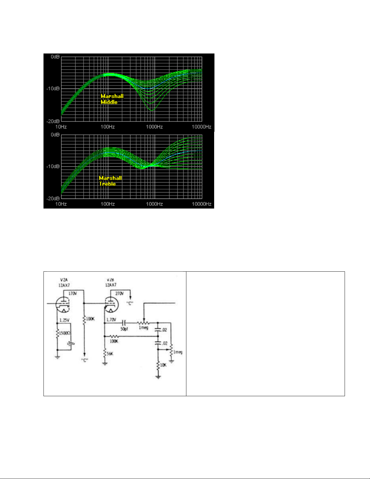
Here are the same charts for Marshall tone controls. As mentioned already, the main points to note are the
smaller range of adjustment, the higher frequency for the middle cut control, and the higher overall signal
level. The smaller adjustment range and higher level are both caused by the use of the 33K resistor in place
of Fender's 100K. The also gives the tone stack a lower input impedance, requiring it to be fed from a lower
output impedance (cathode follower) preamp tube stage.
Trinity Amps 18 Watt uilder’s Guide. Version 3.0
Page - 17
Tube power amplifiers often provide an additional presence control (which reduces negative feedback in the
power amplifier section) to provide a small amount of boost at frequencies above the treble control.
VOX Tone controls
The VOX type Top oost circuit response is used in the TC-15. This is well-known for it’s interactive nature.
When VOX re-designed their AC30 and removed the
EF86, they added a Top oost circuit to regain some
of the high end sparkle the amp had lost. What was
used was the high gain circuit from the 1954 Gibson
GA-77 "Vanguard" - An Amplifier known for it's
'high gain' channel. The interesting point is that the
original Gibson diagrams happen to have an error on
the ass pot, grounding one end that should be left
floating.
Glen Lambert - 2002. For more information see:
http://www.geocities.com/vintage325/topboost.html
Trinity Amps 18 Watt uilder’s Guide. Version 3.0
Page - 18
This error was carried across to the VOX JMI ' rilliance' unit. This affects the way the tone controls interact
and the effect of the ass control on mid band. Normally it would be desirable for the ass control to effect
only the ass content, but in this case the ass control will effect the midrange and to some extent the Treble
when it is at it's extreme travel. Even in correct form the circuit is not ideal. It's a compromise to keep the
component count low, but the error does make it slightly harder to control Treble and ass separately.
This same circuit will be present on every VOX amp that contains a Top oost section.
If you're curious to hear how the tone controls were meant to respond it's not a difficult thing to do. Just
unsolder the ground connection from the ass pot. You can leave it floating or join this terminal to the wiper
to make it a variable resistor.
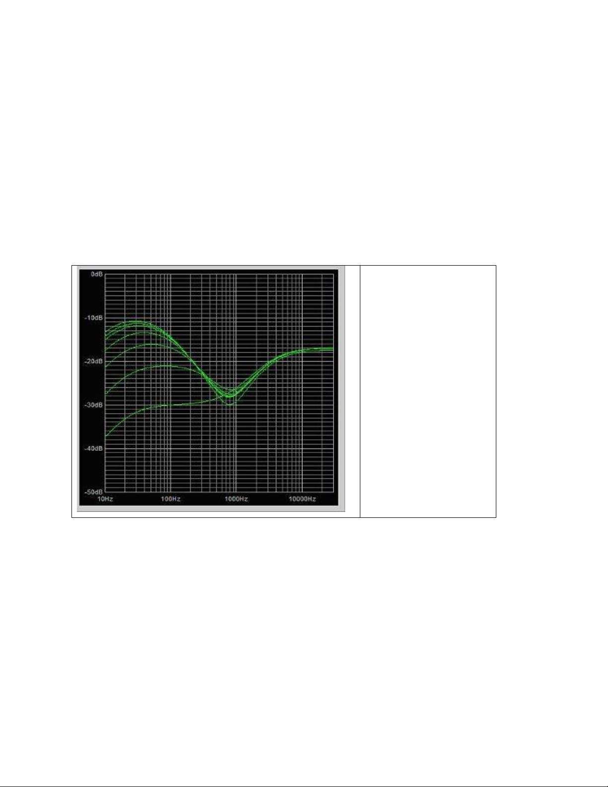
Trinity 15/TC-15 ass
Control Frequency
Response. Note the
interactive effect on Treble
control.

Trinity Amps 18 Watt uilder’s Guide. Version 3.0
Page - 19
Trinity 15/TC-15 Treble
Control Frequency
Response. Note the
interactive effect on ass
control.
Distortion
The overdriven sound of a tube power amplifier is highly desirable, with many different output stage designs
to produce the variety of trademark sounds heard on modern recordings. The only problem is that a tube
power amplifier is only capable of producing this sound at one volume (usually, fairly loud!).
There are probably 3 distinctly identifiable types of tube power amplifiers used:
Leo Fender's classic early designs used 6V6 tubes, and later, the higher powered 6L6's. This gave a
characteristic full and punchy sound, suitable for many styles of the day, and later. Steel and country players
like the chime-like clean sounds, and blues players were quick to discover the classic way it breaks up when
pushed hard. At really high overdrive, though, the sound becomes quite dirty, with bass in particular
sounding flabby.
Marshall designs started as Fender copies, but soon switched to EL34 output tubes, possibly for local supply
reasons. Anyway, the rest is history. These tubes exhibit a softer overdrive transition, and maintain clarity
even at high overdrive levels. They also have a limited middle response, giving rise to the famous Marshall
crunch sound. The lower powered EL84 tubes have similar characteristics.

Trinity Amps 18 Watt uilder’s Guide. Version 3.0
Page - 20
Vox AC30 (and the more popular top boost model) uses a Class A power amplifier design, with the tubes
biased ‘hot’, so while this operates in class A at lower levels, it is a class A design. There's no negative
feedback in the power amp either, so this gives a different sound, often described as a sweeter overdrive.
Listen to rian May's sounds for plenty of good examples.
The Fender and Marshall designs use class A for their output designs, biased with the tubes almost off with
no signal. This is more efficient (more watts per tube), and better for tube life. When you play, tubes take
turns handling each half of the signal. This leads to some (unwanted) distortion as the tubes cross over.
Class A designs are rare in medium to high power guitar amps, but true class A has the tubes operating at half
power, with no signal applied. When you play, the tube fluctuates between full and no power, so there is no
switching to add unwanted distortion. This is a very superficial explanation; please read elsewhere on the
Internet for more detailed descriptions.
Wide Dynamic Range
A plucked guitar string requires a wide dynamic range to handle the initial peak,
and then cleanly amplify the decaying string vibrations. Some poor designs do not have this capability in
their preamp stages, let alone the power amp to handle this. Pre-amplifier stages need generous power rails,
and should not have gain stages which cause the initial plucked part of the string sustain envelope to be
clipped.
Instrument Speakers
Unlike hi-fi speakers, which are designed to keep the coil entirely within the
magnetic field to maximize linearity, instrument speakers are designed to have the coil partially leave the
magnetic field at the extremes of cone travel. This is partly to protect the speaker, but also produces a ‘soft-
clipping’ effect which is desirable with guitar amplifiers. It is also therefore important to match speaker
power ratings reasonably closely with the power of the amplifier. Popular instrument speakers are available
from Tone Tubby, Celestion, Jensen and others.
Note: If you were to use two cabinets hooked directly into the amp, be sure to set the amp at half the
impedance of the cabinets. For example, if your cabinets are 8 ohms each, set the impedance selector to 4
ohms.
Durability
Most musical styles will require the amplifier to be overdriven for extended periods of time,
and the amplifier must be designed to provide this without duress on any components. Common non-guitar
design principles assume that circuitry will be designed to avoid overdrive, and technicians working in this
field have to ‘un-learn’ many basic assumptions. Popular circuits have evolved through trial and error, due to
a general lack of documented knowledge in the field of non-linear amplification.
Road Worthiness
Musical equipment of this type needs both physical and electrical protection. A band
often has its equipment transported and set up by a road crew with little guarantee of physical care. Likewise,
an assumption should be made that the output stage will at times be inadvertently shorted, so most
professional equipment is designed to handle this contingency, preferably electronically, and at the very least
without fuses inside the chassis.
This manual suits for next models
1
Table of contents


