Cable/Wire tracing
CAUTION: Do not connect the transmitter to any wire or cable with an
active circuit of more than 24VAC.
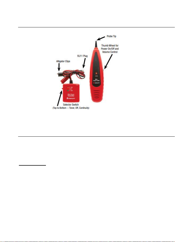
1. Connect the transmitter to the cable
For cables terminated at one end, connect the red alligator
clip to a wire and the black alligator clip to equipment
ground
For un-terminated cables, connect the red alligator clip to one
wire and the black alligator clip to another wire.
For cables with modular connectors, insert the RJ11 plug
directly into the connector.
2. Set the transmitter power switch to the TONE position. The red
TONE LED will turn on.
3. On the probe, rotate the Power/Sensitivity control so that the
POWER LED is on..
4. Hold the insulated probe tip against the wire in question to pick up
the signal generated by the transmitter.
5. Rotate the volume/sensitivity control on the probe for the
appropriate level and sensitivity to identify and trace the wire.
6. The tone will be the loudest on the wires connected to the tone
generator.
Continuity testing
CAUTION: Disconnect power and loads from any circuits to be tested.
1. Connect the test leads to the wire under test.
2. Switch the transmitter to the CONTINUITY position.
3. The CONTINUITY LED will glow GREEN for if the resistance is
less than 10,000 ohms. The LED intensity will be very bright for
very low resistances and will decrease in intensity as resistance
increases.
Identifying telephone cable Tip and Ring –Using
Alligator Clips
1. Switch the transmitter to the OFF position
2. Connect the BLACK clip to ground