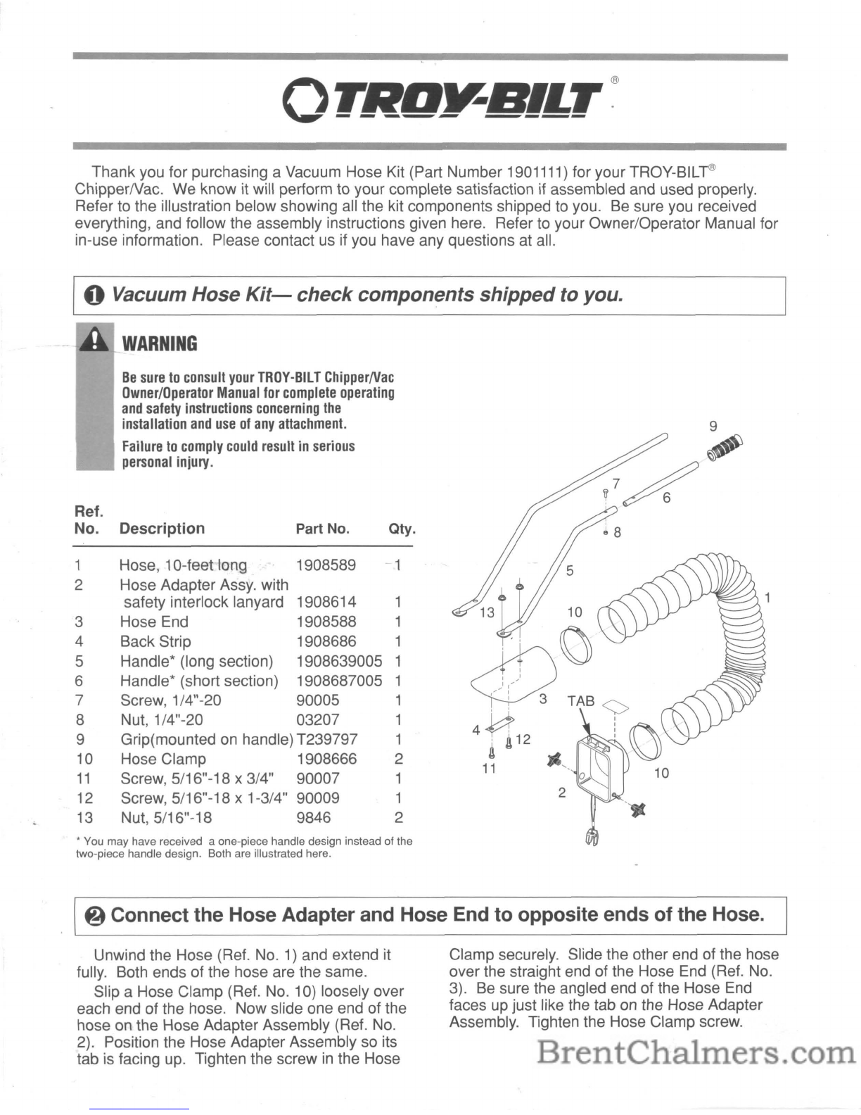
Troy-Bilt 47260 Instruction Manual

$7.50
Owner/Operator
Manual
TROY-BILT®
ChipperNac
•
Safety
•
Assembly
•
Features
and
Controls
•
Operation
•
Maintenance/Repairs
•

Dear Owner:
NOTE:
An
Ownership
Transfer
Card
is
included with this Manual.
This card should be filled out and
returned ONLY if
you
transfer own-
ership
of
your machine
to
someone
else.
Be
sure
to
fill out
and
mail
your
Warranty
Registration
Card,
which
is
located
in your
literature
pack-
1,1,\\\
age.
The
infor-
J'JJ~)'l_
mation contained on the card will
register your machine with us and
entitle you to full coverage under
our Limited Warranty.
Be
Sure
To
Return
Your
Warranty
Registration
Card
This is asafety alert
symbol. It is used in
this Owner/Operator
Manual and
on
your
machine to alert you
to
potential hazards. Whenever
you
see this symbol, read and obey the
safety
message
that
follows
it.
Failure
to
obey the safety message
could result
in
personal injury or
prop-
erty damage.
Thank you for buying aTROY-BILT®
ChipperNac. Your new machine is care-
fully designed and manufactured to give
you superior results and dependable ser-
vice, ifproperly operated and maintained.
You
will find this machine
to
be amost
unique and helpful tool in caring for your
property. Now, you can chip, vacuum
and shred your organic yard debris -
everything from leaves to thick brush,
prunings and branches -with very little
effort and in minimal time.
Please carefully read this Manual.
It
tells you how
to
safely and easily assem-
ble, operate and maintain your machine.
Be sure that you and any other operator
carefully follow the recommended safety
practices at all times. Failure
to
do so
could result in personal injury orprop-
erty damage.
Of
course,
if
you should ever have any
problems or questions, please contact
your local TROY-BILT® ChipperNac
authorized dealer or call
us
Toll-Free.
Our telephone numbers and mailing ad-
dresses are listed on Page 2and on the
back cover
of
this Manual.
We
want
to
be sure that you are com-
pletely satisfied at all times.
This machine meets voluntary safety stan-
dard B71.6-1990, which
is
sponsored by
the Outdoor Power Equipment Institute,
Inc., and is published by the American
Standards Institute, Inc.

Thank you for purchasing aVacuum Hose Kit (Part Number 1901111) for your TROY-BILT®
ChipperlVac. We know it will perform to your complete satisfaction if assembled and used properly.
Refer to the illustration below showing all the kit components shipped to you. Be sure you received
everything, and follow the assembly instructions given here. Refer to your Owner/Operator Manual for
in-use information. Please contact us if you have any questions at all.
oVacuum Hose
Kit-
check components shipped
to
you.
WARNING
Be
sure
to
consult
your
TROY-Bll
T
ChipperNac
Owner/Operator
Manual
for
complete
operating
and
safety
instructions
concerning
the
installation
and
use
of
any
attachment.
Failure
to
comply
could
result
in
serious
personal
injury.
Hose, 10-feet long
1908589-1
Hose Adapter Assy. with
safety interlock lanyard 1908614 1
Hose End 1908588 1
Back Strip 1908686 1
Handle* (long section) 1908639005 1
Handle* (short section) 1908687005 1
Screw, 1/4"-20 90005 1
Nut, 1/4"-20 03207 1
Grip(mounted on handle) T239797 1
Hose Clamp 1908666 2
Screw, 5/16"-18 x3/4" 90007 1
Screw, 5/16"-18 x1-3/4" 90009 1
Nut, 5/16"-18 9846 2
Ref.
No.
1
2
3
4
5
6
7
8
9
10
11
12
13
Description Part No. Qty.
•You may have received aone-piece handle design instead of the
two-piece handle design. Both are illustrated here.
@Connect the Hose Adapter and Hose End to opposite ends of the Hose.
Unwind the Hose (Ref.
No.1)
and extend it
fully. Both ends of the hose are the same.
Slip aHose Clamp (Ref. NO.1
0)
loosely over
each end of the hose. Now slide one end of the
hose on the Hose Adapter Assembly (Ref. No.
2). Position the Hose Adapter Assembly so its
tab is facing up. Tighten the screw
in
the Hose
Clamp securely. Slide the other end of the hose
over the straight end of the Hose End (Ref. No.
3). Be sure the angled end of the Hose End
faces up just like the tab
on
the Hose Adapter
Assembly. Tighten the Hose Clamp screw.

@)
Assemble the 2-piece Handle
and
attach
it
to the angledHose End.
If
you received atwo-p1ece Handle, align the
two Handle Sections (Ref. No's. 5and
6)
as
shown
in
the figure at right, then connect them
using the 1/4"-20 Screw (Ref.
No.7)
and the
1/4"-20 Nut (Ref.
No.8).
Align the two holes at the end of the Handle
with the two holes
in
the angled Hose End. See
the figure at right. Attach the Handle using the
two 5/16"-18 Screws (Ref. Nos.
11
and 12) and
the two 5/16"-18 Nuts (Ref. No. 13). The Back
Strip (Ref.
No.4)
must go over the screws first,
as is shown. Tighten this hardware firmly.
~8
13
,Attach Handle to
V'Hose End
I I
I/
/(
,/
:
4i
~
Place Screws and Back
f":
Strip Inside the Hose End
11
!!12
oConnect the Hose AdapterAssemblyto the ChipperlVac.
First mount the two black plastic screw-on
knobs on the Hose Adapter Assembly (Ref.
No.
2,
other side). Don't tighten them yet.
IMPORTANT: See the TROY-SILT Chipper/
Vac Owner/Operator Manual
for
complete
instructions
on connecting and using the
Vacuum Hose attachment you've assembled.
If you
don't
have an Owner/Operator Manual,
please
contact
the Factory
or
your
local
TROY-SILT Dealer
for
areplacement.
WARNING
Before
changing
vacuuming
attachments
or
screens,
or
before
adjusting
fan
cover,
shut off engine, disconnect
spark
plug
wire from spark plug,
and
allow all
moving
parts
to
come
to
a
complete
stop.
Failure
to
follow
these
instructions
can
result
in
serious
personal
injury.
WARNING
The
TROY-BILT
Chipper/Vac
is
provided
with
a
safety
interlock
system
which
prevents
the
engine
from
starting
unless
a
vacuuming
attachment
and
the
fan
cover
are
installed. It
is
also
designed
to
shut
off
the
engine
if
the
operator
attempts
to
remove
a
vacuuming
attachment
or
the
fan
cover
while
the
engine
is
running.
Never
attempt
to
disconnect
or
to
otherwise
defeat
the
purpose
of
this system. If
the
interlock system fails
to
operate
properly,
shut
off
the
engine
and
do
not
operate
the
equipment
until
the
system
has
been
repaired
and
is
functioning
properly.
Before
using
the
equipment
each
day,
check
the
operation
of
the
safety interlock system
as
exp
lained
in
you
r
TROY
-BILT
Chip
per/Vac
Owner/Operator
Manual.
Failure
to
follow
these
instructions
can
result
in
serious
personal
injury.
OTRD~B1LT®
TROY-Bll
TMANUFACTURING CO., 102nd St. &9th Ave., Troy, New York 12180
For Technical Service call Toll-Free: 1-800-833-6990 -For Parts call Toll-Free: 1-800-648-6776
GARDEN WAY BRANCH CANADA, 1515 Matheson Blvd.
E.,
Unit B11, Mississauga, Ontario L4W 2P5
Call Toll-Free: 1-800-225-3585
1900657 (2/92) Printed
in
U.S.A. ©1992 Garden Way Inc.

OWNER/OPERATOR
MANUAL
SUPPLEMENT
Installation
and
Use
Instructions
for
New
Style
Engine
Throttle
Control
(Carefully
read
this
Supplement
and
then
insert
it
at
Page
26
of
your
TROY-BILT®
ChipperNac
Manual)
1
You
have received anew style Engine Throttle
•Control that replaces the engine ON/OFF switch
that
is
described in your Manual. Use the infor-
mation on these pages to install and use the new
throttle control and save this Supplement for
future reference.
NEW
LOOSE
HARDWARE
2.
3.
This Supplement contains important Parts
Catalog information. Be sure to update your
Parts Catalog
as
described on Page
3.
If
you have any questions or concerns, contact
your local authorized service dealer, or call or
write our Technical Service Department. See
Page 4for telephone and address information.
NOTE: The two #10-24 x1/2" self-threading, Hex/Washer Screws (see
Key "N" on Page 9
of
your Manual) are no longer required.
FOR
MODEL:
4HP
5HP
KEY
QTY.
The loose parts hardware bag con-
tains three new parts that are not
shown or listed on Page 9
of
your
Manual. These parts will be used
to install the new Throttle Control.
Refer to the table to the right and to
Figure Ibelow to identify these
new parts.
NEW
ASSEMBLY
PROCEDURE
A
B
C
DESCRIPTION
1
Bracket
•
2
Pan
Hd.
Screw,
#10-24
x2".................................................. •
2
NutiLockwasher,
#10-24...................................................... •
•
•
•
The
following procedure replaces
Step 3
on
Page
10
of
your
Owner/Operator
Manual.
A. Complete Steps 1and 2on
Pages 9and 10
of
your Manual.
B. Place the bracket (A, Fig.
1)
over the lower set
of
holes on the
left side handlebar as shown (on
the 4HP Model there is only one
set
of
holes). Make sure the long
side
of
the bracket is on the out-
side edge
of
the handlebar.
C. Carefully unwrap the throttle
control cable assembly (D, Fig.
1)
from around the engine. Route the
cable straight back (to the inside
of
the left side handlebar support),
and then up along the bottom
of
the handlebar.
D. Place the lever assembly on the
outside
of
the bracket. Install two
pan hd. screws (B) and nut/lock-
washers (C)
as
shown. Tighten the
hardware securely.
(Continued on Page 2) Figure 1:
Attach
throttle
control
(shown
on
5HP Model handlebar).

NOTE: Complete the following
steps that apply
to
your model
(either 4HP or 5HP) ChipperNac.
E. 4HP MODEL:
a.) Secure the cable
to
the handle-
bar with acable tie located approx-
imately 5-inches below the throttle
lever (see Fig. 2).
b.) Complete Steps 6through 9on
Pages 12-13
of
your Manual.
F.
5HP MODEL:
a.) Complete Step 4on Pages
10-11
of
your Manual.
b.) Complete Steps 5-A through
5-C on Page
11.
Ignore Step 5-D.
c.) Tuck the Gear Shift Lever
Cable below the new throttle cable
bracket. Then, secure the Throttle
Control Cable, the Gear Shift
Lever Cable, and the Wheel Drive
Bail Cable
to
the handlebar with a
cable tie located approximately 5-
inches below the throttle lever (see
Fig. 3).
Cable
Tie
Figure
2:
On 4HPModel, secure
throttle cable with cable tie
as
shown.
d.) Complete Steps 6through 9on
Pages 12-13
of
your Manual.
Cable
Tie
Figure
3:
On 5HP Model, secure
throttle cable,
gear
shift
levercable
and
wheel drive
bail
cable with
cable tie
as
shown.
THROTTLE
CONTROL
OPERATING
INSTRUCTIONS
Your new engine throttle control
(see Fig. 4) has three positions in-
dicated on the control body:
FAST, SLOW, and STOP.
•When starting the engine, place
the lever at the FAST setting.
•Use the settings between FAST
and SLOW to regulate the engine
speeds. For heavy duty chipping
and shredding, you will want to
use the FAST setting. For light
duty chipping and shredding, or for
transporting your machine, you
may want to use aslower engine
speed. Doing so will result in re-
duced noise volume and gasoline
consumption.
•Move the lever all the way
back
to
STOP
to
shut
offthe
engine. Remove any hearing pro-
tection and listen
to
the sound
of
the machine
as
it slows down.
There is an audible tone that
changes
as
the cutting blades slow
down. Listen for all parts
to
come
to
acomplete stop.
IMPORTANT: Refer to Page 26
of
your
Manual
for complete
"Starting
and
Stopping the
Engine" instructions. Your new
throttle
control replaces the
On/Off
Switch described on
that
page.
2
---STOP
--SLOW
--FAST
Figure
4:
Throttle settings.

THROTTLE
CONTROL
ADJUSTMENTS
The throttle control settings are
factory adjusted and unnecessary
adjustments should not be made.
However,
if
the engine does not
start
or
stop, or
if
it does not re-
spond to various throttle lever set-
tings' then the following adjust-
ments may be necessary.
DANGER
To
prevent personal injury,
stop
the
engine,
disconnect
the
spark
plug
wire,
and
let
the
engine
and
muffler
cool
before
inspecting
or
adjust-
ing
the
throttle
control.
1. With the engine shut
off
and the
spark plug wire disconnected, put
the throttle control lever (on the
handlebar) in the FAST setting.
2.
If
the throttle control is properly
adjusted, the Control Lever on the
engine (see Fig. 5) should touch
the High Speed Stop tab located on
the throttle control bracket.
If
the
Control Lever does not touch the
High Speed Stop tab, proceed to
Step 3.
3. Loosen the Cable Clamp Screw
(Fig. 5) until the Throttle Cable is
free to move in the Cable Clamp
(do not remove the screw).
4. Push the Throttle Cable up until
the Control Lever touches the High
Speed Stop tab.
5. Hold the Control Lever at this
position and securely tighten the
Cable Clamp Screw.
6. Test the function
of
the throttle
control by moving it back and
forth between the FAST and STOP
positions.
If
properly adjusted, the
Control Lever should contact the
High Speed Stop tab and the Shut
Off
Clip.
7.
If
you are unable to properly
adjust the cable, contact your local
authorized dealer or the Factory.
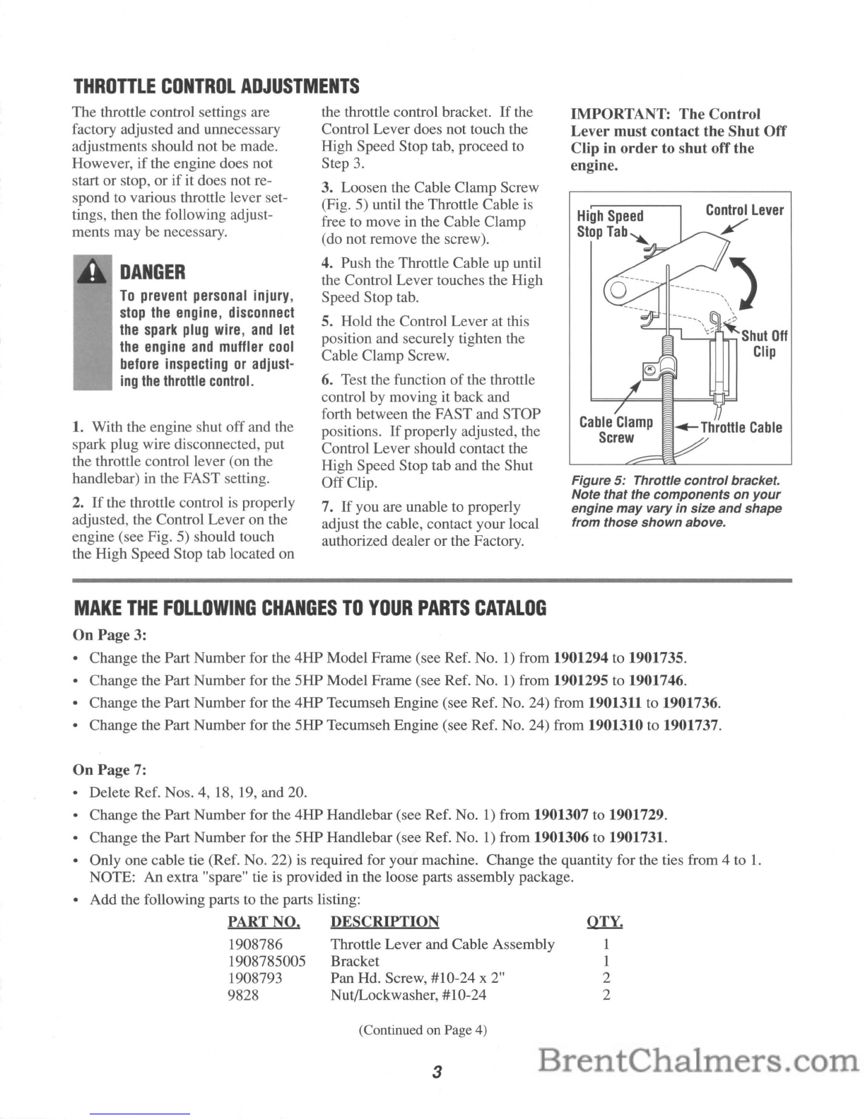
IMPORTANT: The Control
Lever must contact the Shut Off
Clip in
order
to shut offthe
engine.
High
Speed
Stop
Tab
.........
----------,
1
,,,,
~Shut
Off
Clip
Figure
5:
Throttle
control
bracket.
Note that the components on
your
engine
may
vary
in
size
and
shape
from those
shown
above.
OTY.
1
1
2
2
MAKE
THE
FOLLOWING
CHANGES
TO
YOUR
PARTS
CATALOG
On
Page 3:
•Change the Part Number for the
4HP
Model Frame (see Ref.
No.1)
from 1901294 to 1901735.
•Change the Part Number for the 5HP Model Frame (see Ref.
No.1)
from 1901295 to 1901746.
•Change the Part Number for the
4HP
Tecumseh Engine (see Ref. No. 24) from 1901311 to 1901736.
•Change the Part Number for the 5HP Tecumseh Engine (see Ref. No. 24) from 1901310 to 1901737.
On
Page 7:
•Delete Ref. Nos. 4, 18, 19, and 20.
•Change the Part Number for the
4HP
Handlebar (see Ref.
No.1)
from 1901307 to 1901729.
•Change the Part Number for the 5HP Handlebar (see Ref.
No.1)
from 1901306 to 1901731.
•Only one cable tie (Ref. No. 22) is required for your machine. Change the quantity for the ties from 4to
1.
NOTE:
An
extra "spare" tie is provided in the loose parts assembly package.
•Add the following parts to the parts listing:
PART NO. DESCRIPTION
1908786 Throttle Lever and Cable Assembly
1908785005 Bracket
1908793
Pan
Hd. Screw, #10-24 x2"
9828 Nut!Lockwasher, #10-24
(Continued on Page 4)
3

PARTS
CATALOG
CHANGES
(Continued
from
Page
3)
On
Page
10:
•Change the Part Number for the Chipper Chute Assembly (see Ref.
No.1)
from 1901297 to 1901738.
•Change the Part Number for the Operating Instructions Decal (see Ref.
No.5)
from 1901151 to 1901715.
On
Page
12:
•Delete the Engine On/Off Switch and Wire Harness Assembly that is shown in the drawing.
•Delete the three cable clips (Ref.
No.1)
that are located on the back, right comer
of
the frame. Note that the
4HP Model now has acable clip located on the back, left comer
of
the frame. This clip holds the throttle cable
to the frame.
On
Page
13:
•The new wiring arrangements for the 4HP and 5HP Models are shown in Figures 6and 7.
Figure
6:
4HP
Model
Wiring
Arrangement.
NEW
MODEL
NUMBERS
Figure
7:
5HP
Model
Wiring Arrangement.
The Model Numbers that appear on the front cover
of
the Owner/Operator Manual have changed as follows:
Model No. 47260 is now 47278 Model No. 47271
is
now 47280
Model No. 47261 is now 47279 Model No. 47272 is now 47281
TROY-BILT MANUFACTURING COMPANY, 102nd
51.
and
9th
Ave., Troy, N.Y. 12180
For Parts Service, call Toll-Free: 1-800-648-6776· For Technical Service, call Toll-Free: 1-800-833-6990
GARDEN
WAY
BRANCH CANADA, 1515 Matheson Blvd. E.,
Unit
B11,
Mississauga,
Ontario
L4W
2P5
Call Toll-Free: 1-800-225-3585
1901523 (6/92) Printed
in
U.S.A. ©1992 Garden Way Inc.

Owner's
Record
Please write the Model and
Serial numbers of your
machine
in
the spaces
provided. You can find
the location of these
numbers by referring to
the illustration below.
Model Number:
Serial Number:
Model/Serial
Number
Location
Table
of
Contents
SERVICE
INFORMATION
2
SECTION
1:
SAFETY
3
Training
3
Preparation
.4
Operation
,
.4
Maintenance
and
Storage
6
Decals
7
SECTION
2:
ASSEMBLY
8
SECTION
3:
FEATURES
AND
CONTROLS
14
Features
and
Controls
Identification
14
Description
of
Operation
15
Vacuuming
Attachments
and
Shredder
Screens
16
SECTION
4:
OPERATION
17
Vacuuming
and
Chipping
Guide
18
Adjusting
Handlebar
Height
19
Filling
Fuel
Tank
19
Installing
or
Emptying
the
Collection
Bag
20
Installing
the
Vacuuming
Attachments
21
Safety
I
nterlock
System
22
Removing
or
Changing
A
Shredder
Screen
23
Walk-Behind
Operation
and
Transporting
Your
Machine
24
Starting
and
Stopping
the
Engine
26
Using
the
Vacuuming
Attachments
27
Chipper
Operation
29
Clearing
the
Machine
of
Clogs
or
Jams
33
SECTION
5:
MAINTENANCE/REPAIRS
34
Required
Maintenance
Schedule
34
Checking
and
Changing
Engine
Oil
35
Servicing
the
Air
Cleaner
Assembly
36
Cleaning
the
Engine
Cooling
System
36
Servicing
the
Spark
Plug
37
Carburetor
and
Ignition
System
Information
37
Servicing
the
Engine
On/Off
Switch
Assembly
37
Servicing
the
Safety
Interlock
System
37
Lubrication
38
Check
Nuts
and
Bolts
38
Sharpening
or
Replacing
the
Chipper
Cutting
Blade
38
Replacing
the
Fan
Blades
.40
Repairing
a
Damaged
Shredder
Screen
.41
Replacing
the
Drive
Belt
.41
Traction
Drive
Adiustments
.42
Replacing
the
Wheel
Drive
Bail
Cable
.43
Adjusting
the
Gear
Shift
Lever
Cable
.44
Replacing
the
Gear
Shift
Lever
Cable
.44
Off-Season
Storage
.45
TrOUbleshooting
.46
INDEX
48
1

telephone book under "Engines-
Gasoline" (call us
if
you need as-
sistance in obtaining engine
service or parts).
Please remember that your en-
gine is covered by the engine man-
ufacturer's Limited Warranty. Any
unauthorized work performed on
the engine during the warranty pe-
riod may void the warranty. For
full details on the engine manufac-
turer's Limited Warranty, refer to
the separate Engine Owner's
Manual.
number, description, and quantity
of
the part you need. Then, call or
write our Parts Department,
being sure to provide the
Model and Serial Numbers
of
your machine.
Our trained parts special-
ists will gladly assist you
if
you have any difficulty in
identifying the exact part that
you need.
If
you have any
Questions or
Problems...
If
You
Need
Parts:
Factory specified replacement
parts for your machine are
available from either your
TROY-BILT® Chipper/Vac
authorized dealer or directly
from the Factory.
To order apart from
the Factory, refer to
your separate Parts
Catalog to find the part
...Please contactyour local TROY-BILT® Chipper/Vac
authorized dealer
or
call
or
write the Factory. When calling
or writing, please be sure to provide the Model
and
Serial
Numbers
of
your
machine (refer to Page 1).
If
your engine
should ever re-
quire service
/5h---lL--r+-~~,.J1
or repair,
contact your
nearest
autho-'------I
rized engine service
dealer.
To find the name
of
your nearest
authorized engine service dealer,
look in the Yellow Pages
of
the
If
You
Need
Engine
Service:
Canada
(Toll
Free)
~
t==:J
Canada
M-F,
8
a.m.
to
4:30
p.m.
For
Technical
Service
and
Parts
Service:
1-800-225-3585
Canada
GARDEN
WAY
BRANCH
CANADA,
1515
Matheson
Blvd.
E,
Unit
B11,
Mississauga,
ON
L4W2P5
U.S.A.
(Toll
Free)
U.S.A.
TROY-BILT
MFG.
CO.,
102nd
St.
&
9th
Ave.,
Troy,
N.Y.
12180
U.S.A.
M-F,
8
a.m.to
7
p.m.
Sat.
9
a.m.
to
4
p.m.
For
Parts
Service:
1-800-648-6776
For
Technical
Service:
1-800-833-6990
HOW
TO
REACH
US
2

Seetio
Safety
4. Familiarize yourself with all
of
the safety and operating decals on
this equipment and on any
of
its
attachments or accessories.
S.
Do not run engine in an en-
closed area. Engine exhaust con-
tains carbon monoxide gas, a
deadly poison that is odorless, col-
orless, and tasteless.
Do
not oper-
ate this equipment near buildings,
windows, or air conditioners.
6. Do not allow hands or any
other part
of
the body or clothing
inside the vacuum inlet, chipper
chute, discharge deflector, or near
any moving part.
Cutting blades
begin to rotate
when engine
starts and slow
down gradually
after engine
is
shut off.
WARNING
TO
ALL
CALIFORNIA
AND
OTHER
POWER
EQUIPMENT
OPERATORS
A
Under California law, and under the laws of several other states,
you
are not permitted
to
operate
an
internal combustion engine
using hydrocarbon fuels
on
any forest covered, brush cov-
'--~
ered, or grass covered land, or
on
land covered with grain,
hay, or other flammable agricultural crop, without
an
en-
gine spark arrester
in
continuous effective working order.
The engine
on
your power equipment, like most outdoor power equipment,
is
an
internal combustion engine that burns gasoline, ahydrocarbon fuel. Therefore,
your power equipment must
be
equipped with aspark arrester muffler
in
continu-
ous effective working order. The spark arrester must be attached to the engine
exhaust system
in
such amanner that flames or heat from the system will not ig-
nite flammable material. Failure of the owner/operator of the equipment
to
com-
ply with this regulation
is
amisdemeanor under California law,
and
may also
be
a
violation of other state and/or federal regulations, laws, ordinances, or codes.
Contact your local fire marshal or forest service for specific information about
what regulations apply
in
your area.
1. Read this Owner/Operator
Manual and the separate Engine
Owner's Manual carefully before
operating this equipment. Be
completely familiar with the con-
trols and the proper use
of
this
equipment.
2. Never allow children or un-
trained adults to operate this
equipment.
3. Keep the area
of
operation clear
of
all persons, particularly small
children, and pets. Keep by-
standers at least
25
feet away from
the area
of
operation.
TRAINING
This
is
a
safety
alert
symbol.
It
is
used
in
this
Owner/Operator
Manual
and
on
your
machine
to
alert
you
to
potential
hazards.
Whenever
you
see
this symbol,
read
and
obey
the
safety
message
that fol-
lows
it.
Failure
to
obey
the
safety
message
could
re-
sult
in
personal
in-
jury
or
property
damage.
Please
read
and
follow all
of
the
safety
rules
in
this
Safety
Section. Failure
to
comply
could
result
in
serious
personal
injury
or
property
damage.
If
you
should
lend
this
equip-
ment
to
another
person,
make
sure
that
he
or
she
reads,
un-
derstands,
and
always
follows
these
safety
instructions.
If
you
are
not
completely
sure
about
any
of
the
information
found
here
or
elsewhere
in
the
Manual,
please
contact
either
your
local
authorized
dealer
or
the
factory
for
assistance.
3

Safety
7. Before inspecting or servicing
any part
of
the equipment, shut
off
engine, disconnect spark plug wire
from spark plug, and make sure
PREPARATION
o
o
1.
Wear approved safety glasses
when operating this equipment.
The operation
of
any powered ma-
chine can result in foreign objects
being thrown by high-speed rotat-
ing parts.
2. Do not wear loose-fitting cloth-
ing
or
jewelry that can get drawn
into the vacuum inlet or chipper
chute, or that can get caught by
moving parts.
3. Do not operate this equipment
on apaved, gravel,
or
hard surface
unless the collection bag is in-
stalled. Discharged material may
bounce from ahard surface.
Always select alevel, earthen sur-
face when operating without the
collection bag.
OPERATION
1. Before starting this equipment,
make certain that the chipper
chute, vacuum inlet, and discharge
deflector are empty. Disconnect
spark plug wire before making
these checks.
that all moving parts have come to
acomplete stop. Be aware that ro-
tating blades slow down gradually
after engine is shut off.
4.
Do
not process material through
the chipper chute, the rake-in tray,
or the vacuum hose when the
equipment is on uneven ground.
5. Before starting engine, check
that all screws, nuts, bolts, and
other fasteners are properly secured.
Replace any damaged or unreadable
warning and operating decals.
6. Wear work gloves, sturdy
footwear, and hearing protection
when operating this equipment.
7. Do not operate this equipment
without avacuuming attachment or
vacuum inlet cap installed.
8. On self-propelled models, put
Gear Shift Lever in Park (P) posi-
tion and release Wheel Drive Bail
before starting engine.
9. All operators shall use extra
care when handling gasoline and
other fuels. Gasoline and its va-
pors are higWy flammable and ex-
plosive.
To
help prevent afire or
explosion:
2. Never carry passengers on this
equipment. They could
falloff
and
be seriously injured,
or
they could
interfere with safe operation.
3. Do not allow hands or any other
part
of
the body or clothing inside
the vacuum inlet, chipper chute,
discharge deflector, or near any
moving part.
4. When vacuuming or chipping,
be extremely careful that pieces
of
metal, rocks, bottles, cans, or other
foreign objects are not included.
5. Before vacuuming, inspect the
area where the equipment is to be
4
8. Do not operate this equipment
if
you are under the influence
of
alcohol, medication, or when tired
or ill.
a.
Use an approved fuel con-
tainer.
b. Never remove the gas cap or
add fuel while the engine is
running. Allow the engine to
cool before refueling.
c.
Keep matches, smoking mate-
rials, open flames, and sparks
away from fuel tank and fuel
container.
d. Fill fuel tank outdoors and
with extreme care. Never fill
fuel tank indoors.
e.
Replace caps on fuel tank
and fuel container and clean
up spilled fuel before starting
engine.
f. Leave 1/2-inch air space at
top
of
fuel tank to allow for
expansion
of
fuel.
g.
The macl1ine or fuel container
shall not be stored inside
where there is an open flame
or spark, or where ignition
sources are present such as
hot water and space heaters,
furnaces, clothes dryers,
stoves, electric motors, etc.
used and remove all metal, bottles,
cans, or other foreign objects.
6. Do not vacuum any burning or
smoldering materials such as
cigars, cigarettes, ashes, or cinders.
7. Do not vacuum areas that have
been recently treated with fertiliz-
ers, pesticides
or
herbicides.
Follow chemical manufacturer's
safety instructions regarding con-
tact with treated areas.
8. Do not vacuum flammable liq-
uids such as gasoline, kerosene,
diesel fuel, paint thinner, etc.

9.
If
equipment strikes any foreign
object or starts making an unusual
noise or vibration, immediately
shut offengine, disconnect spark
plug wire from spark plug, and
allow all moving parts to come to
acomplete stop. Then take the
following steps:
a.
Inspect for damage.
b.
Replace or repair any damaged
parts.
c.
Check for and tighten any loose
parts.
10.
If
equipmentjams or becomes
clogged, immediately shut offen-
gine, disconnect spark plug wire
from spark plug, and allow all
moving parts to come to acom-
plete stop. Use only awooden
stick to clear away debris.
11. Before changing vacuuming
attachments or screens, or before
adjusting fan cover, shut offen-
gine, disconnect spark plug wire
from spark plug, and allow all
moving parts to come to acom-
plete stop.
12. Keep all guards, covers, and
deflectors in place and in good
working condition.
13. Do not operate the equipment
unless the chipper chute and the
fan cover assembly are securely
installed.
14. Always stand clear
of
dis-
charge area when operating equip-
ment without collection bag in-
stalled. Material exits at high
speed from the discharge deflector.
15. Keep your face and body
safely away from chipper chute.
When chipping, stand on either
side
of
chute and keep arms per-
pendicular (at a900angle) to
chute inlet.
16. Do not overreach when feed-
ing material into chipper chute.
Keep proper balance and footing at
all times.
17. Do not operate equipment
with vacuum snout unless collec-
tion bag
is
installed.
18. Shut off the engine and dis-
connect the spark plug wire from
the spark plug before transporting
the machine in avehicle or trailer.
19. Before removing or installing
collection bag, shut offengine, dis-
connect spark plug wire from
spark plug, and allow all moving
parts to come to acomplete stop.
20. Empty the collection bag after
each use. Decomposing debris
could generate enough heat to
catch fire. Before emptying the
collection bag, shut offengine, dis-
connect spark plug wire from
spark plug, and allow all moving
parts to come to acomplete stop.
21. Exercise extreme caution on
slopes and avoid excessively steep
slopes. On the self-propelled
model, do not shift gears on
slopes.
22. Never operate this equipment
at high transport speeds on slip-
pery surfaces.
23. Look behind and use care
when operating in reverse.
24. Do not allow any part
of
the
engine, especially around the cool-
ing fins and muffler, to become
clogged with leaves, oil, grease or
any other combustible material.
25. When operating without the
collection bag installed, do not
use your hands or feet to remove
material from the ground beneath
the discharge area. Use along-
handled shovel or along stick to
safely remove material.
5
Safety
26. Remove hearing protection and
watch for traffic when operating
near, or when crossing roadways.
27. Never leave equipment unat-
tended when engine
is
running.
Shut off engine and disconnect
spark plug wire from spark plug
before leaving equipment.
28. Use only attachments and ac-
cessories that are approved for use
with this equipment.
29. Operate equipment only
in
daylight or in good artificial light.
30. Do not operate equipment un-
less the rubber retainer flap inside
the chipper chute
is
in good condi-
tion, is securely installed, and is
hanging freely inside the chute.
31. Do not tamper with the engine
governor settings. The governor
controls the maximum safe operat-
ing speed and protects the engine
and all moving parts from damage
caused
by
excessive speed.
Authorized service shall be sought
if
aproblem exists.
32. This equipment
is
provided
with asafety interlock system
which prevents the engine from
starting unless avacuuming attach-
ment and the fan cover are in-
stalled. It is also designed to shut
offthe engine
if
the operator at-
tempts to remove avacuuming at-
tachment or the fan cover while
the engine
is
running. Never at-
tempt to disconnect or to otherwise
defeat the purpose
of
this system.
If the interlock system fails to op-
erate properly, shut off the engine
and do not operate this equipment
until the system has been repaired
and
is
functioning properly.
Before using the equipment each
day, check the operation
of
the
safety interlock system as ex-
plained on Page 22
of
this Manual.

Safety
MAINTENANCE
AND
STORAGE
1. When equipment
is
stopped for
servicing, inspection, storage, or
to
change an attachment or accessory,
make sure the spark plug wire
is
disconnected from the spark plug.
Allow the engine to cool before
making any inspections, adjust-
ments, etc.
2. Maintain equipment and all at-
tachments and accessories in a
clean, and safe working condition.
SAFETY
DECALS
3. Never perform any maintenance
while the engine
is
running or when
the spark plug wire
is
connected to
the spark plug, except where specif-
ically instructed
to
do
so.
4.
Never store this equipment with
fuel
in
the fuel tank inside abuild-
ing where fumes may reach an
open flame or spark, or where igni-
tion sources are present such as hot
water and space heaters, furnaces,
clothes dryers, stoves, electric mo-
tors, etc.
5. Allow engine to cool before
storing
in
any enclosure.
6. Store gasoline in acool, well-
ventilated area, safely away from
any spark- or flame-producing
equipment. Store gasoline in an
approved container, safely out
of
the reach
of
children.
7. Use only original equipment re-
placement parts. Parts manufac-
tured
by
others could present a
safety hazard even though they
may fit on this equipment.
8. Store this equipment where
children will not have access to it.
Disconnect the spark plug wire
from the spark plug.
9. Check collection bag frequently
for deterioration or wear and re-
place worn bags. Use only origi-
nal-equipment replacement bags.
Bags manufactured by others could
present safety hazards.
10. Refer to the Engine Owner's
Manual and to
"Off
Season
Storage" in Section 5
of
this
Manual for important storage in-
structions
if
equipment
is
to be
stored for an extended period.
Make certain that all safety decals on this equipment are kept clean and in
good condition. The decals are shown (at reduced sizes) below and on the
next page.
If
you need areplacement decal, please refer to the Parts
Catalog that accompanied this Manual.
ROTATING
CUTTING
BLAOESI
TO
AVOID
SERIOUS
INJURY:
KEEP
HANDS
AND
FEET
OUT
OF
VACUUM
INLET
WHEN
MACHINE
IS
RUNNING.
DO
NOT
OPERATE
WITHOUT
A
VACUUMING
ATTACHMENT
OR
VACUUM
INLET
CAP
INSTALLED.
BEFORE
ClEARING
BLOCKAGES,
CHANGING
VACUUMING
ATTACHMENTS,
DR
ADJUSTING
FAN
COVER,
STOP
ENGINE,
DISCONNECT
SPARK
PLUG
WIRE,
AND
WAIT
FOR
ALL
MOVING
PARTS
TO
STOP.
1901'.7(1192)
....
ON CHIPPER CHUTE
(FACING HANDLEBARS)
6
....
ON FRONT
OF MACHINE,
ABOVE
VACUUM INLET

PLACE
FOOT
0
AGAINST
WHEEL
WHEN
PULLING
ENGINE
RECOIL
STARTER
190115711921
...
NEXT TO LEFT
FRONT WHEEL
¢
SAFETY
INTERLOCK
SWITCH
1901267
(1921
...
ON
FRONT,
LEFT SIDE OF FAN
HOUSING
Safety
AWARNING
TO
AVOID
SERIOUS
INJURY:
•
TO
AVOID
SEVERE
BURNS,
00
NOT
TOUCH
MUFFLER
OR
~
AOJACENT
AREAS.
•
TO
AVOID
A
FIRE
HAZARO,
KEEP
LEAVES,
GRASS
ANO
OTHER
COMBUSTIBLE
MATERIALS
AWAY
FROM
ENGINE
ANO
MUFFLER.
...
ON
ENGINE COVER
A
DANGER
ROTATING
CUTTING
BLAOES!
TO
AVOID
SERIOUS
INJURY:
•
DO
NOT
OPERATE
MACHINE
UNLESS
DISCHARGE
DEFLECTOR
IS
SECURELY
INSTALLED.
•
BEFORE
CLEARING
BLOCKAGES
FROM
THE
DISCHARGE
DEFLECTOR,
STOP
ENGINE,
DISCONNECT
SPARK
PLUG
WIRE,
AND
WAIT
FOR
ALL
MOVING
PARTS
TO
STOP.
•
DO
NOT
OPERATE
MACHINE
WITH
VACUUM
SNOUT
UNLESS
COLLECTION
BAG
IS
INSTALLED.
•
BEFORE
INSTALLING
OR
REMOVING
THE
COLLECTION
BAG,
STOP
ENGINE,
DISCONNECT
SPARK
PLUG
WIRE,
AND
WAIT
FOR
ALL
MOVING
PARTS
TO
STOP.
190"'9
('192)
...
ON UPPER
HALF
OF
DISCHARGE DEFLECTOR
~
ROTATING
CUTTING
BLADES
INSIDE
CHIPPER
CHUTE
INLET
WILL
CAUSE
SERIOUS
INJURY.
DO
NOT
OPERATE
MACHINE
UNLESS
CHIPPER
CHUTE
IS
SECURELY
INSTALLED.
1901145
(1192)
...
NEXT TO CHIPPER
CHUTE
~
ROTATING
CUTTING
BLADES
INSIDE
DISCHARGE
DEFLECTOR
OPENING
AND
BEHIND
FAN
COVER
WILL
CAUSE
SERIOUS
INJURY.
DO
NOT
OPERATE
MACHINE
UNLESS
DISCHARGE
DEFLECTOR
AND
FAN
COVER
ARE
SECURELY
INSTALLED.
'901144
1'192)
...
ON
REAR, RIGHT SIDE OF
FAN HOUSING
ADANGER
MATERIALS
EXIT
FROM
DISCHARGE
DEFLECTOR
AT
HIGH
SPEEDS!
KEEP
HANDS,
FEET
AND
FACE
AWAY
FROM
DISCHARGE
DEFLECTOR
TO
AVOID
SERIOUS
'90'204
('192)
INJURY.
...
ON LOWER
HALF
OF
DISCHARGE DEFLECTOR
ROTATING
CUTTING
BLADES!
TO
AVOID
SERIOUS
INJURY,
KEEP
HANDS
OUT
OF
CHIPPER
CHUTE
WHILE
MACHINE
IS
RUNNING.
--------------------------
NO
HANDS
BELOW
THIS
LINE
1901148
(1192)
...
INSIDE CHIPPER CHUTE
7

Assembly
C. Assembly should be done on a
clean, level surface.
If
you need
to move the machine, be careful
not to severely bend any cables.
NOTE: All references to left,
right, front and rear
of
the ma-
chine are determined by standing
behind the handlebars and facing
the direction
of
forward travel.
STEP
1:
Unpacking
and
Checking
Contents
A.
After unpacking the shipping
carton, compare the contents with
the parts shown and listed on the
next page.
B.
If
any parts are missing or
damaged, contact your local ser-
vice dealer or call the Factory for
assistance.
IMPORTANT:
Motor
oil
must
be
added
to
the
engine before
it
is
started.
The
procedure
for
adding
oil
is
explained in Step 7
of
these assembly instructions.
Subjects covered in this Section:
•Unpacking
and
Checking Contents
•Install the Handlebars
•Install the Engine ON/OFF Switch
•Attach the
Gear
Shift Lever Cable
(SHP Model)
•Install the Wheel Drive Bail Cable
(SHP Model)
•Install the Chipper Chute
•Add Motor Oil to the Engine
•Install the Collection Bag
•Install the Vacuum Attachment
Inspection
After
Delivery
Inspect your machine immediately
after it has been delivered. Make
sure that neither the carton nor the
contents have been damaged.
If
you find or suspect any damage,
contact the carrier (trucking com-
pany) right away. Inform them
of
the specific damage and that you
wish to file aclaim.
To
protect
your rights, be sure to put this in
writing to the carrier within
15
days after your machine arrives.
The carrier will let you know how
to proceed with your claim.
Please let us know
if
you need any
assistance with this matter.
WARNING
Tools
Needed:
(1)
Hammer*
Please
carefUlly
follow
the
steps
in
this
Section
to
properly
assem-
ble
your
new
machine.
These
steps
will
not
take
very
long
and
they
will
assure
you
of
having
as-
sembled
your
machine
correctly.
To
prevent personal injury
or
property
damage,
do
not
attempt
to
start
the
engine
until
all
assem-
bly
steps
are
complete
and
you
have
read
and
understand
the
safety
and
operating
instructions
in
this
Manual.
8

Shipping
Carton
Contents
Assembly
1
ChipperNac
Assembly
(5HP
model
shown)
•
1
Handlebar
Assembly
(5HP
model
shown)
•
1
Safety
Goggles
•
1
Collection
Bag
•
1
Chipper
Chute
(5HP
model
shown)
•
1
Vacuum
Snout
..
1
Rake-In
Tray......................................................................... •
1
Flange
Locknut,
1/4"-20
..
2
Knob,
5/16"-18
•
2
Knob,
1/4"-20
•
1
Curved
Head
Screw,
1/4"-20
x
1-5/8"
..
2
Curved
Head
Screw,
5/16"-18
x
2"........................................
•
6
Flange
Lock
Hex
Head
Screw,
5/16"-18
x
5/8",
Grade
5........
•
2
Self-Thread,
HexlWasher
Screw,
#10-24
x
1/2"....................
•
5
Cable
Tie,
Plastic
(three
ties
supplied
with
4HP
model)
•
1
Ear
Plugs,
One
Pair
•
1
Cap
Push
Nut
.
2
Star
Lock
Washer,
5/16"
•
KEY
OTY
A
B
C
o
E
F
G
H
I
J
K
L
M
N
o
P
a
R
Table
1-
Carton
Contents
Parts
List
DESCRIPTION
FOR
MODEl:
4HP
5HP
•
•
H~
I,J
9

Assembly
STEP
2:
Install
the
Handlebars
A. Protect the handlebars from
being scratched during assembly
by placing cardboard or padding
on the ground behind the two
large
wheels on the machine.
B. With the curved end
of
the han-
dlebars facing up, place the two
handlebar ends on the inside
of
the
handlebar mounting brackets (A,
Inset #1, Figure 2-2). On the 5HP
model, be careful not to severely
bend the gear shift lever cable at-
tached to the left side handlebar.
C. Loosely install a5/16"-18 x
5/8" flange lock hex head screw
(B, Inset #1, Figure 2-2) through
the lower holes in each handlebar
and mounting bracket.
D. The handlebars are adjustable
to one
of
three operating positions:
High,
Medium
and Low. There is
E 0
\
~'
Medium
Inset
#2
also a
Storage
position which
places the handlebars upright.
Refer to Inset #2, Figure 2-2 to
identify the bracket holes that are
used for the various positions.
E. Lift the handlebars and align one
of
the two holes in each handlebar
with the selected hole in each
bracket. Insert 5/16"-18 x
2"
curved
head screws (C, Inset #2) through
the handlebars and brackets.
F.
Insall astar lock washer (D) on
each screw.
G. Add a5/16"-18 knob (E) on
each screw and tighten securely.
F.
With a1/2" wrench, securely
tighten the two screws (B, Inset #1)
in the handlebar ends.
STEP
3:
Install
the
Engine
ON/OFF
Switch
A. The engine ON/OFF switch
assembly (A, Figure 2-3) is con-
nected to along wire that leads
from the back
of
the engine.
B. Run the wire
up
the inside
edge
of
the right side handlebar.
C. With a5/16" wrench, attach
the switch bracket with two #10-
24 x1/2" self-threading
hex/washer head screws (B,
Figure 2-3).
D. Secure the switch wire to the
handlebar with two cable ties (G,
Figure 2-2). Leave the ties alittle
loose to allow the wire to "stretch"
if the handlebars are later placed
in the storage position. Trim off
any excess tie length with scissors.
Figure 2-3: Install Engine ON/OFF
Switch.
STEP
4:
Attach
the
Gear
Shift
Lever
Cable
(5HP
Model
Only)
The GEAR
SHIFf
LEVER (F,
Figure 2-2) is attached to the left
side handlebar. The cable leading
from the lever must be connected
to the transaxle (transmission) in-
side the mainframe.
IMPORTANT:
Do
not
severely
bend
or
kink
the
cable
as
dam-
age to
the
cable will result.
Figure 2-2
10

Route
Gear
Shift
lever
Cable
BELOW
Handlebar.
A.
With a3/8" wrench, remove the
three self-threading screws from
the transaxle access cover (A,
Figure 2-4) located on the rear
of
the mainframe. Remove the cover.
B. Move the GEAR SHIFT
LEVER (F, Figure 2-2) to the No.
4setting as indicated on the decal
(push lever all the way forward
until it stops moving).
C. With a3/8" wrench, loosen the
cable clamp screw (B, Figure 2-4)
and swing the cable clamp
(C)
to
one side.
IMPORTANT:
The
transaxle
shifting
arm
(D,
Figure
2·4) is
preset
in
4th
gear. Do
not
move
the
shifting
arm
before installing
the
cable.
D. Gently route the cable (E,
Figure 2-4) below the handlebar
and insert the "Z" hook end
of
the
cable wire into the top
of
the
transaxle shifting arm (D).
E. Place the cable sheath
in
the
groove on the top
of
the transaxle
and swing the clamp over the
cable. Check that the GEAR
SHIFT LEVER (on handlebar) is
still in the
No.4
setting. Then,
tighten the clamp screw securely.
F.
Check the function
of
the cable
by
moving the GEAR SHIFT
LEVER all the way back to P
(Park) and then all the way forward
to
No.4.
You
should feel the lever
engage seven distinct positions
(with six "clicks" in between).
If
not, repeat Steps Bthrough
F.
NOTE: Be sure that the cable
sheath does not move within the
clamp while performing this test.
I---:.W'--------lo
E
Assembly
G. Reinstall the transaxle access
cover with the three cover mount-
ing screws removed previously.
NOTE: Put the GEAR SHIFT
LEVER
in
N(Neutral) to move the
machine without the engine run-
ning. (A certain amount
of
stiff-
ness or drag
is
normal when the
machine
is
moved
in
Neutral.)
ot
A
Figure 2-4:
Install
Gear
Shift
Lever
Cable.
STEP
5:
Attach
the
Wheel
Drive
Bail
Cable
(5HP
Model
Only)
A.
The wheel drive bail cable (A,
Figure 2-5)
is
connected to the
bracket on the rear, left side of the
mainframe. Run the cable
up
the
inside edge of the left side handle-
bar and align the hole
in
the cable
clamp (B) with the
upper
of
the
two holes that are located afew
inches below the GEAR SHIFT
LEVER.
B. Insert a1/4"-20 x1-5/8" curved
head screw (C, Figure 2-5)
through the handlebar and into the
clamp. Add a1/4"-20 flanged
locknut (D) and tighten securely
using a7/16" wrench.
C. Slip the cable eyelet (E, Figure
2-5) over the stud (F) on the wheel
drive bail. Place awood block be-
hind the stud and use ahammer
to
tap the cap push nut (G) onto the
stud (the push nut can also be
pressed on with apair
of
large-
sized pump or parallel jaw pliers).
D. Secure the gear shift lever
cable and the wheel drive bail
cable to the handlebar with two
cable ties (H, Figure 2-2). Leave
the ties alittle loose to allow the
cables to "stretch" ifthe handle-
bars are later placed in the storage
position. Trim off any excess tie
length with scissors.
11
C
~
--
Figure 2-5:
Install
Wheel
Drive
Bail
Cable.

Assembly
STEP
6:
Install
the
Chipper
Chute
A.
In the following steps, do not
touch the chipper cutting blade (A,
Figure 2-6) that is located inside
the chute mounting hole (the blade
may not be visible due to its ship-
ping position on the rotor assem-
bly.) The blade
is
very
sharp
and
can cause personal injury.
B. For shipping purposes, two hex
head screws are installed in the
holes labeled
No.1
and 4in Figure
2-6. With a1/2" wrench, remove
the two screws and throw them
away. They
are
not for reuse
on
the
machine.
C. With the long end
of
the chip-
per chute mounting flange (B)
pointing down, tilt the top of the
chute slightly away from the
machine and slide the chute lip (C)
into the chute mounting hole. It
may
be
easier
if
someone helps
support the chute while you install
the four screws.
D.
On the 5HP model, twist the
chute
in
aclockwise direction until
the bottom left corner
of
the
mounting flange fits into the nar-
row slot between the engine body
and the machine housing.
E. On all models, align the four
holes
in
the mounting flange with
the four holes
in
the machine hous-
ing. Using your fingers, loosely
install four 5/16"-18 x5/8" flange
lock hex head screws (D), follow-
ing the numbered sequence shown
in
Figure 2-6. After all four
screws are in place, tighten them
securely with a1/2" wrench.
F.
Look inside the top
of
the chute
and check that the rubber retainer
flap
is
hanging freely inside the
chute.
NOTE: Ahinged, chute extension
is attached to the top
of
the chipper
chute. The chute extension
is
shipped from the factory in its
folded, storage/light-duty chipping
position.
To
unfold the screen for
heavy-duty chipping, refer to the
instructions found on Page 30.
DANGER
Do
not
operate
the
machine
unless
the
chipper
chute
is
securely
installed.
Serious
personal injury
can
result
from contact with rotating
cutting
blades
if
the
chipper
chute is not securely in-
stalled.
(f)p--
(f)p--
D
(f)p--
(f)p--
Figure 2-6: Installation
of
Chipper Chute.
12
This manual suits for next models
3
Table of contents
Other Troy-Bilt Yard Vacuum manuals