Turbo E9Trb Operation instructions

U s e A n d M a i n t e n a n c e I n s t r u c t i o n s
Charge Displacem e n t P ro b e E 9 T r b F o r D u s t C o n t r o l
I n M n 25 S T S C
e n R e v .0 0
T U R B O s . r . l .
D u s t F i l t e r C o m p o n e n t s
V i a P o / 5 2 0 8 1 1 C e s a n o M a d e r n o ( M B ) I t a l y T e l + + 9 0 6 2 5 7 4 0 2 4 F a x + + 9 0 6 2 5 7 4 0 9 2
1
Charge Displacement Probe E9Trb
U s e A n d M a i n t e n a n c e I n s t r u c t i o n

U s e A n d M a i n t e n a n c e I n s t r u c t i o n s
Ch a r g e D i s p l a c e m e n t P ro b e E 9 T r b F o r D u s t C o n t r o l
2 T U R B O s . r . l .
D u s t F i l t e r C o m p o n e n t s
V i a P o / 5 2 0 8 1 1 C e s a n o M a d e r n o ( M B ) I t a l y T e l + + 9 0 6 2 5 7 4 0 2 4 F a x + + 9 0 6 2 5 7 4 0 9 2
I n M n 2 5 S T S C
R e v . 0 0 e n
Description ____________________________________________________________________ 3
Operating Principle ____________________________________________________________ 3
Table Of Available Versions ____________________________________________________ 3
PWM Output 4/20 A __________________________________________________________ 4
Serial Output RS485 ____________________________________________________________ 4
Installation _____________________________________________________________________ 4
Accessories ____________________________________________________________________ 8
Startup _________________________________________________________________________ 8
Output Status And Functionality _______________________________________________ 9
Ter inals Connections Layout _________________________________________________ 10
Self-Acquisition ________________________________________________________________ 11
Test Procedure _________________________________________________________________ 11
Electrical Connections _________________________________________________________ 12
Additional Functions - Data Analysis __________________________________________ 14
Technical Features ____________________________________________________________ 15
Maintenance __________________________________________________________________ 16
Warnings ______________________________________________________________________ 16
Declaration Of Confor ity Of The Manufacturer _______________________________17

U s e A n d M a i n t e n a n c e I n s t r u c t i o n s
Ch a r g e D i s p l a c e m e n t P ro b e E 9 T r b F o r D u s t C o n t r o l
I n M n 2 5 S T S C
e n R e v .0 0
T U R B O s . r . l .
D u s t F i l t e r C o m p o n e n t s
V i a P o / 5 2 0 8 1 1 C e s a n o M a d e r n o ( M B ) I t a l y T e l + + 9 0 6 2 5 7 4 0 2 4 F a x + + 9 0 6 2 5 7 4 0 9 2
Description
The charge displacement probe is a microprocessor-based instrument, pre-
calibrated, complete with two digital outputs optically isolated open collector
type, a RS485 serial interface to configure and / or download the data, a PWM
output 4/20 mA and a set of LEDs for synthetic indications of operation modes.
The probe is designed to detect and measure dust emissions caused by breakage
of bag filters.
There are no limitations in installations due to different types of powders.
Operating Principle
The charge displacement probe uses the principle of the displacement of the
electric charge in the electrode, induced by the electrical charges, carried by
dust immersed in a gaseous fluid.
The amount of electric charge dynamically induced on the electrode is
proportional to the amount of dust present in the gaseous fluid.
An increase in the concentration of dust causes a proportional increase of the
signal that reaches the microprocessor.
Applying mathematical algorithms, the individual powder particles are counted to
be able to calculate their concentration in milligrams per cubic meter.
The computed values can be stored internally in order to be drafted in the future,
or sent via RS485 serial transmission, or PWM 4/20 mA to an external control
unit for further analysis and / or views.
Table Of Available Versions
Ver s io n Re s o lu ti o n
Th r e sh ol d
1*
Th r e sh ol d
2*
Pw m
4/ 2 0 M a
F
ul l
Sc al
e
@ 20 m a
Se l f
cquisi ti o n Rs 4 85
E9 P RL 00
3
0, 1 m g/m
3
5 m g/m
3
10 m g/m
3
No
10/ 50 m g/m
3
Si
Si
E9 P RL 00
5
0, 1 m g/m
3
5 m g/m
3
10 m g/m
3
Si
10/ 50 m g/m
3
No
Si
E9 P RL 00
6
0,
0
1 m g/m
3
5 m g/m
3
2
mg/m
3
Si
2
/50 mg /m
3
No
Si
* If using self-acquisition function, the values (in mg/m ) of threshold 1 and
threshold 2 do not match to this table.

U s e A n d M a i n t e n a n c e I n s t r u c t i o n s
Ch a r g e D i s p l a c e m e n t P ro b e E 9 T r b F o r D u s t C o n t r o l
4 T U R B O s . r . l .
D u s t F i l t e r C o m p o n e n t s
V i a P o / 5 2 0 8 1 1 C e s a n o M a d e r n o ( M B ) I t a l y T e l + + 9 0 6 2 5 7 4 0 2 4 F a x + + 9 0 6 2 5 7 4 0 9 2
I n M n 2 5 S T S C
R e v . 0 0 e n
PWM Output 4/20 mA
The switch J1 defines the type of the range only for the PWM output 4/20 mA.
With J1 open, the full scale value (20 mA) will be achieved with a dust
concentration of 10 mg/m or equal to 2 mg/m for probe E9PRL006.
With J1 closed, the full scale value (20 mA) will be achieved with a dust
concentration of 50 mg/m or 10 mg/m for probe E9PRL006.
Serial Output S485
The RS485 serial interface allows the transfer of data between the probe and
other equipment.
Installation
Fixing On V ertical Du ct Fixing On Ho rizont al D uct
1 T hr ea d e d S le ev e ¾”G as
2 C on tin ue W el di ng O n Th e Ci rc u m fer en c e O f The Sl eev e
The triboelectric probe must be installed on a metallic duct electrically connected to
the ground, so as to ensure shielding from electromagnetic noise.
The probe must be away from obstacles such as valves, chokes, bends which can
disturb laminar air motion, change the uniform concentration of dust, both
upstream and downstream of the probe, the distance is at least 5 times the
diameter of the pipe.
The probe should be protected from direct sunlight.
Must be fitted with a slight tilt angle, the sensitive rod downwards, so as to
facilitate the fall of drops of condensation, prevent fluid retention on the electrode.
In the figure of mounting on vertical duct, the inclination is represented in an
excessive way than necessary which are few degrees 1° to °, for the sake of
clarity.

U s e A n d M a i n t e n a n c e I n s t r u c t i o n s
Ch a r g e D i s p l a c e m e n t P ro b e E 9 T r b F o r D u s t C o n t r o l
I n M n 2 5 S T S C
e n R e v .0 0
T U R B O s . r . l .
D u s t F i l t e r C o m p o n e n t s
V i a P o / 5 2 0 8 1 1 C e s a n o M a d e r n o ( M B ) I t a l y T e l + + 9 0 6 2 5 7 4 0 2 4 F a x + + 9 0 6 2 5 7 4 0 9 2
5
View Enti re Condu ct
In ner Duc t Wi ev
For proper measurement of powders, the measuring electrode of the probe must
exceed ¾ of the diameter of the pipe.
In order to minimize any dust deposits on the electrode is not recommended
mounting the probe with the enclosure underneath the pipeline.
The electrode must have a length slightly less than the diameter of the pipe it
must not touch the pipe or other metal objects and / or blocking.
Please note, that the quality of the signal is always proportional to the amount of
air / powder mixture that invests the electrode.
After determining the location of the installation, screw the probe into the
conduct, by interposing an adapter ¾G and without force.
Di mensio ns

U s e A n d M a i n t e n a n c e I n s t r u c t i o n s
Ch a r g e D i s p l a c e m e n t P ro b e E 9 T r b F o r D u s t C o n t r o l
6 T U R B O s . r . l .
D u s t F i l t e r C o m p o n e n t s
V i a P o / 5 2 0 8 1 1 C e s a n o M a d e r n o ( M B ) I t a l y T e l + + 9 0 6 2 5 7 4 0 2 4 F a x + + 9 0 6 2 5 7 4 0 9 2
I n M n 2 5 S T S C
R e v . 0 0 e n
In st allatio n Of The Pr o be On Discharg e Du ct For D if ferent Ex ha ust Fu mes Temp er at ur es
Fumes Te mperatur es Par t Numb e r Descripti on
< = + 60 °C 201058 Threaded Sleeve F. /4"G L040
< = + 120 °C 201060 Threaded Sleeve F. /4"G L100
< = + 180 °C 201062 Threaded Sleeve F. /4"G L150

U s e A n d M a i n t e n a n c e I n s t r u c t i o n s
Ch a r g e D i s p l a c e m e n t P ro b e E 9 T r b F o r D u s t C o n t r o l
I n M n 2 5 S T S C
e n R e v .0 0
T U R B O s . r . l .
D u s t F i l t e r C o m p o n e n t s
V i a P o / 5 2 0 8 1 1 C e s a n o M a d e r n o ( M B ) I t a l y T e l + + 9 0 6 2 5 7 4 0 2 4 F a x + + 9 0 6 2 5 7 4 0 9 2
7
Pro be In st al lat io n Wit h Lo ng Ste m nd St em Isolate d V ersion
1 C ol la r F or Th e F a s teni ng O f T h e E l ec tr o de
2 S u pp or t F o r Pro be E le ctr o de Mad e O f Te fl o n T o F ix O n T h e C on d uc t
3 S u pp or t F o r Pro be W it h Sl eev e To B e F i xe d O n Th e Co nd uc t
4 C on tin uo u s We ld ing On Slee ve C i r c um fer enc e
5 ¾ "Ga s Threa de d S l e e v e
Support the electrode of the probe in the longer versions of 500 mm, as
described in the assembly drawing, it is recommended to avoid damage and
breakages.
The support for the electrode must be made in material plastic insulating, the
electrode does not be in contact with metallic parts that alter the measurements.

U s e A n d M a i n t e n a n c e I n s t r u c t i o n s
Ch a r g e D i s p l a c e m e n t P ro b e E 9 T r b F o r D u s t C o n t r o l
8 T U R B O s . r . l .
D u s t F i l t e r C o m p o n e n t s
V i a P o / 5 2 0 8 1 1 C e s a n o M a d e r n o ( M B ) I t a l y T e l + + 9 0 6 2 5 7 4 0 2 4 F a x + + 9 0 6 2 5 7 4 0 9 2
I n M n 2 5 S T S C
R e v . 0 0 e n
Accessories
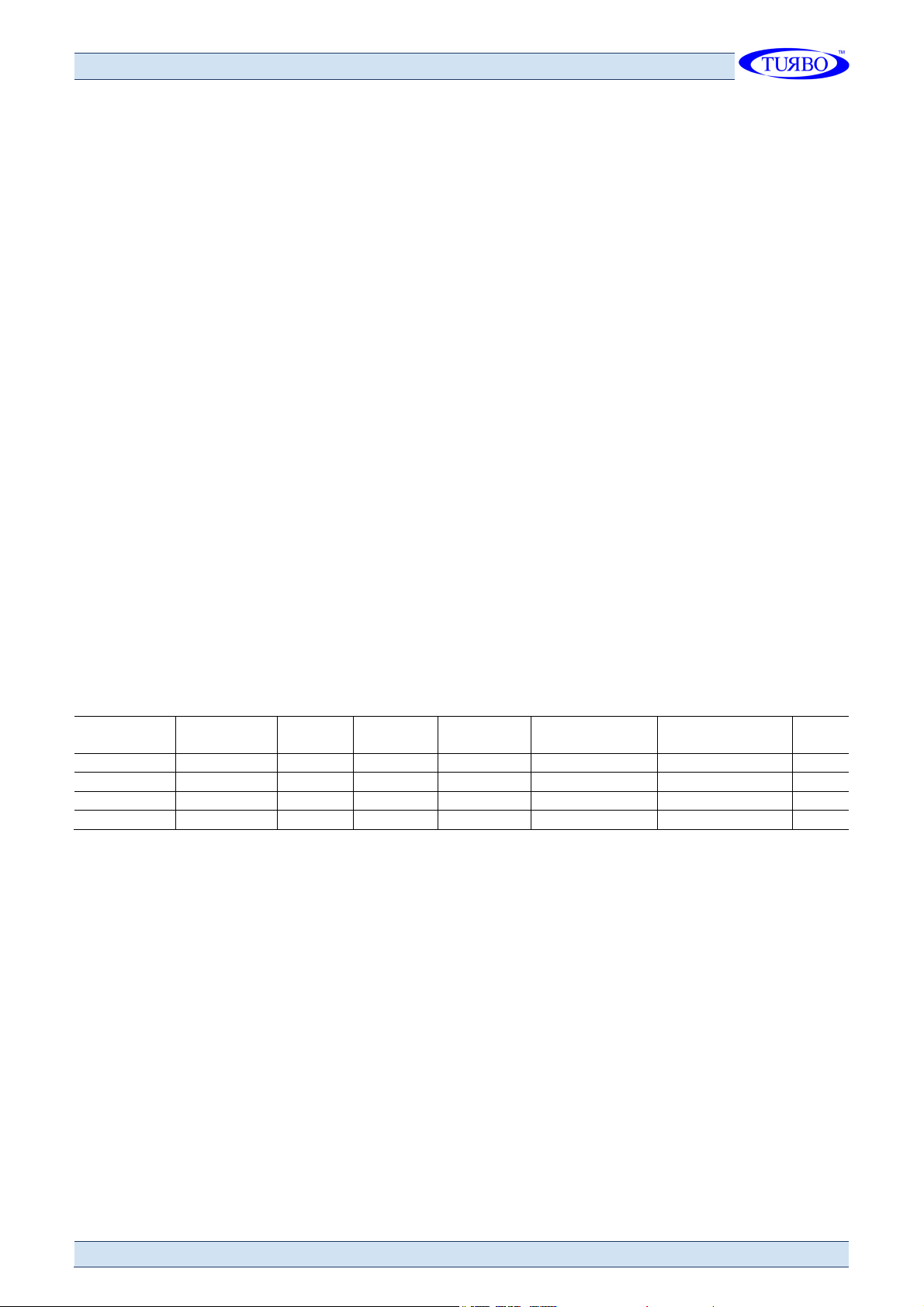
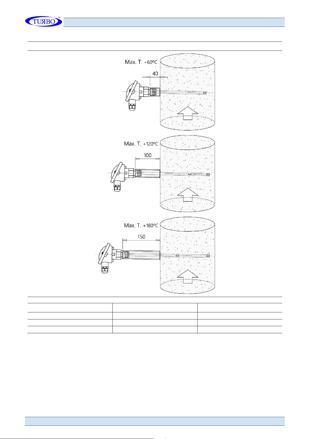
Ex tension s nd dapt atio ns For El ectrode I ns ta ll atio n On Pi pelines Of Variou s Diame te rs
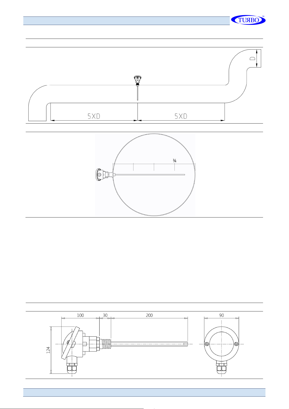
Le ng h t
50 mm
100 m m
200 m m
400 m m
Th r e ad M4 m 10 mm
Ma te r i al
In o x
Stee l
d. 8 m m
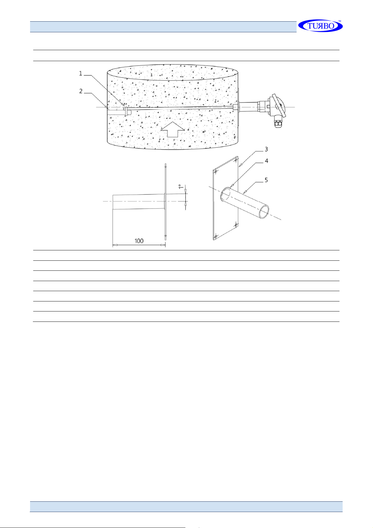
The extensions of the electrodes must be joined together using a medium
strength thread locker to prevent loosening due to vibration, shock and
temperature fluctuations.
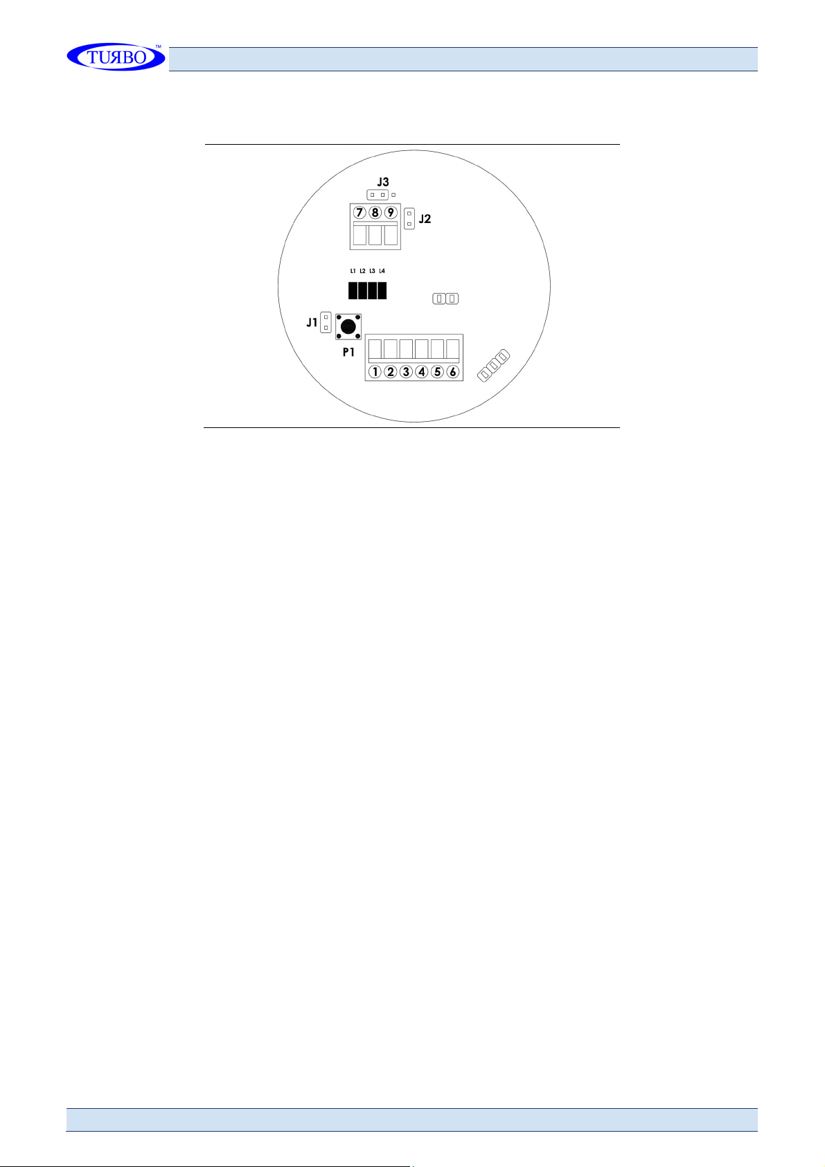
Startup
After powering up the probe and verified the green led L1, it is necessary to wait
for a warm-up time of minutes, during which the probe is measuring but the
outputs are disabled.
After this period of time, if the jumper J1 is left OFF, disengaged, the probe will
operate in manual mode with preset thresholds from the default settings.
If the jumper J1 is inserted, the probe will work with thresholds set
automatically. in this condition, the probe will wait for the press of the button
P1, this state will be indicated by the led L2 mode "a" that is slowly blinking.
To start the self-acquisition: hold down P1 button for 5 seconds, the led will light
steadily L2 (mode "b"), and wait until the led turned off after about 4 minutes,
at this point the acquisition will be completed and the values will be stored in a
solid-state memory, which will keep them even if the probe will be de-energized.
N. B . v al ue s a r e, obtai ne d for t he pr o b e , th e r efe renc e for t h e a c t i v at io n o f t h e o ut p ut s , the n b e
und er s to od a s o p er at i ng va l ue s w it h "r eg u l a r " q uan tit y o f d us t, s o i t i s re co m m en d ed to p er fo r m
the s el f- ac q uis i ti on by c ho o s i ng the m o m e nt con s id er e d m o s t s uit ab le du r i ng pr oc es s in g .
If you want to store new values (eg. changes of working conditions), run new self-
acquisition by pressing P1 as described above.

U s e A n d M a i n t e n a n c e I n s t r u c t i o n s
Ch a r g e D i s p l a c e m e n t P ro b e E 9 T r b F o r D u s t C o n t r o l
I n M n 2 5 S T S C
e n R e v .0 0
T U R B O s . r . l .
D u s t F i l t e r C o m p o n e n t s
V i a P o / 5 2 0 8 1 1 C e s a n o M a d e r n o ( M B ) I t a l y T e l + + 9 0 6 2 5 7 4 0 2 4 F a x + + 9 0 6 2 5 7 4 0 9 2
9
Output Status And Functionality
Status
Alarm 1
Output U1 On = exceeded during the normal measure of the factory value
(see table) or the self acquired multiplied 5 times (multiplication factor x 5).
Alarm 2
Output U2 On = exceeded during the normal measure of the factory value
(see table) or the self acquired multiplied 10 times (multiplication factor x 10).
Fault
output U On = failed the test operation, triggered by a negative pulse (min 0.5
sec.) on pin (Test Input): If pin is connected to a short time to pin 2 (Negative
Power Supply) is automatically activated the test procedure that verifies the proper
operation of the entire probe.
The lack of activation of the output U and its Led L4 indicate proper operation of
the probe and passing the test
Outputs
U1 (pin 7) Normally open output with J2 opened; normally closed with J2 closed.
U2 (pin 8) Normally open output with J2 opened; normally closed with J2 closed.
U (pin 9) Normally open output with J2 opened; normally closed with J2 closed.

U s e A n d M a i n t e n a n c e I n s t r u c t i o n s
Ch a r g e D i s p l a c e m e n t P ro b e E 9 T r b F o r D u s t C o n t r o l
1 0 T U R B O s . r . l .
D u s t F i l t e r C o m p o n e n t s
V i a P o / 5 2 0 8 1 1 C e s a n o M a d e r n o ( M B ) I t a l y T e l + + 9 0 6 2 5 7 4 0 2 4 F a x + + 9 0 6 2 5 7 4 0 9 2
I n M n 2 5 S T S C
R e v . 0 0 e n
Terminals Connections Layout
Led Description:
L1 : ON = +V voltage s present.
L2 : ON = warm up / self-acquisition / serial switching.
L : ON = output U1 ON (pin 7) irregular flashing.
L4 : ON = output U2 ON (pin 8).
L2 + L : flashing = probe vitality (probe ON).
L2: irregular flashing = serial connection activated.
Jumpers Description:
J1 : Operation range only for PWM 4/20 mA output.
J1 open = full scale (20 mA) at 10 mg/m or 2 mg/m for probe E9PRL006.
J1 closed = full scale (20 mA) at 50 mg/m or 10 mg/m for probe E9PRL006.
J2 : inversion of outputs logic.
With J2 open, output contacts (solid state relay) normally open,
With J2 closed, output contacts(solid state relay) normally closed.
J : setting common to the positive / negative (see connection example 1).
Button Description:
P1 : button to self-acquisition (if provided).
Terminals Description:
1 = Positive Supply
2 = Negative Supply
= Test Input For Probe Operation Check
4 = Serial Rs485 (A)
5 = Serial Rs485 (B)
6 = Output Pwm 4/20 Ma
7 = Output Threshold U1
8 = Output Threshold U2
9 = Fault Output U

U s e A n d M a i n t e n a n c e I n s t r u c t i o n s
Ch a r g e D i s p l a c e m e n t P ro b e E 9 T r b F o r D u s t C o n t r o l
I n M n 2 5 S T S C
e n R e v .0 0
T U R B O s . r . l .
D u s t F i l t e r C o m p o n e n t s
V i a P o / 5 2 0 8 1 1 C e s a n o M a d e r n o ( M B ) I t a l y T e l + + 9 0 6 2 5 7 4 0 2 4 F a x + + 9 0 6 2 5 7 4 0 9 2
1 1
Self-Acquisition
The probe allows two setup modes:
The manual setup provides for the operation of the thresholds in function of a
default value set by the manufacturer or on demand.
The automatic setup provides the acquisition of the value, the normal
concentration of dust in normal operating conditions and in fully automatic mode
by pressing the button P1.
The switch J1 defines the type of setup.
The output OUT1 will go ON exceeded 5 times the normal concentration (CN) and
will provide a pre-alarm.
N. B . ctiv at i n g t h e s el f- a c q ui s i ti o n, t he v a lues ( i n m g / m 3) o f the thr es ho ld s
1 a nd 2 w i l l no t m a tc h w it h th e ta bl e r e l a tiv e to the av a i l ab le ve rs i on s .
Test Procedure
To test the proper operation of the probe, connect pin (test input) to pin 2
(negative power), for a longer time than 0.5 sec.
The led relating to fault threshold (led 4) and the system will start a procedure
for the verification of the proper functioning of the entire probe.
Will be verified with all the circuits and all the amplification stages of input,
including the presence of leakage current on the electrode.
Two cases can occur:
1) after about 0 sec. from the start of the test, the fault output U will be
activated for about 60 seconds. This is the condition of failure the test.
2) after about 90 seconds. from the start of test, the fault output U is not
activated.
This is the condition of passing the test.
In any case, after about 90 seconds from the start of test, the probe will resume
the normal operation mode regardless of the result of the test.
In case of failure of the test, it is recommended to remove the probe and provide
a careful cleaning of the electrode and the insulator, so you should also check for
the presence of water infiltration.
Next, replace the probe and repeat the test.

U s e A n d M a i n t e n a n c e I n s t r u c t i o n s
Ch a r g e D i s p l a c e m e n t P ro b e E 9 T r b F o r D u s t C o n t r o l
1 2 T U R B O s . r . l .
D u s t F i l t e r C o m p o n e n t s
V i a P o / 5 2 0 8 1 1 C e s a n o M a d e r n o ( M B ) I t a l y T e l + + 9 0 6 2 5 7 4 0 2 4 F a x + + 9 0 6 2 5 7 4 0 9 2
I n M n 2 5 S T S C
R e v . 0 0 e n
Electrical Connections
Ground Connection
Use the cable that is supplied with the probe, secure under one of the two screws
securing the cover, positioning the washer under the lug.
The other lug must be screwed to the pipe that must be grounded.

U s e A n d M a i n t e n a n c e I n s t r u c t i o n s
Ch a r g e D i s p l a c e m e n t P ro b e E 9 T r b F o r D u s t C o n t r o l
I n M n 2 5 S T S C
e n R e v .0 0
T U R B O s . r . l .
D u s t F i l t e r C o m p o n e n t s
V i a P o / 5 2 0 8 1 1 C e s a n o M a d e r n o ( M B ) I t a l y T e l + + 9 0 6 2 5 7 4 0 2 4 F a x + + 9 0 6 2 5 7 4 0 9 2
1
Connecting Power And Signals
The probe must be supplied with a voltage between 20 and 0V DC.
The opto isolated open collector outputs (protected by a self-resetting fuse)
accept a maximum voltage 48 VAC and a maximum current of 100 mA. PWM
current output 4/20 but is fully opto-isolated. The probe is galvanically isolated
from the power supply.
Electrical Connection Sample 1
Negativ e Co mmon R elay Po si ti ve Co m mo n R elay
Electrical Connection Sample 2
Ter mi nal Of Gm8 2 6 s d B al a n ce Th e Unus ed Lin es With 4 k 7 O hm Resist o rs
Th reshold 1 Th reshold 2

U s e A n d M a i n t e n a n c e I n s t r u c t i o n s
Ch a r g e D i s p l a c e m e n t P ro b e E 9 T r b F o r D u s t C o n t r o l
1 4 T U R B O s . r . l .
D u s t F i l t e r C o m p o n e n t s
V i a P o / 5 2 0 8 1 1 C e s a n o M a d e r n o ( M B ) I t a l y T e l + + 9 0 6 2 5 7 4 0 2 4 F a x + + 9 0 6 2 5 7 4 0 9 2
I n M n 2 5 S T S C
R e v . 0 0 e n
Electrical Connection Sample Of 4/20 m Output
U1 U tilize r Eg PLC
Additional Functions - Data Analysis
The presence of the serial output RS485 can transfer to an external unit the
values read by the probe.
In the chart below, shows a typical example of display (via the Excel program) of
the variation of concentration of the powder as a function of time.
In abscissa there is the time variable (seconds), while in the ordinate is placed
the induced current from the charges carried by the gaseous fluid, or,
alternatively, and after a calibration procedure on the system, the value of the
concentration of dust in mg/m .
Because processing of the data is performed mathematically by the internal
microprocessor, it is possible, through the serial line to enter any type of
functional analysis.
In the example, you can see the response of the probe to changes in the
coefficient of a CF exponential filter. When CF increases, the microprocessor will
eliminate the points derivative of greater, reaching the expected value.
CF with elevated the probe will act as optimally detector threshold, while lower
with CF will be preferred operation the analytical.

U s e A n d M a i n t e n a n c e I n s t r u c t i o n s
Ch a r g e D i s p l a c e m e n t P ro b e E 9 T r b F o r D u s t C o n t r o l
I n M n 2 5 S T S C
e n R e v .0 0
T U R B O s . r . l .
D u s t F i l t e r C o m p o n e n t s
V i a P o / 5 2 0 8 1 1 C e s a n o M a d e r n o ( M B ) I t a l y T e l + + 9 0 6 2 5 7 4 0 2 4 F a x + + 9 0 6 2 5 7 4 0 9 2
1 5
Technical Features
Power supply 20 / 0 Vdc
Maximum power consumption 1 W
Resolution 0,1 mg/m
, 0,01 mg/m
see versions
Range settings Automatic / Manual
Size dust particles > of 0. µm
Type of measurable products Dust particles in gaseous fluid
Flow velocity > of 4 m/s
Measuring principle Charge Displacement
Alarm 1 threshold See table of available versions
Alarm 2 threshold See table of available versions
Alarm threshold (fault) Automatically activated by the function of test
Alarm outputs n. outputs with solid state relay, fuse-
protected auto resetting
Maximum current outputs 100 mA
Maximum applicable voltage
outputs 48 V
Output functions
Adjustable normally closed or normally open.
Common to negative or positive (see wiring
examples)
Probe working temperature < of 140 º C
Working pressure of the probe < 2 bar's
Electrode material Stainless steel aisi 04
Box material Aluminum
Moisture < 95% Non Condensing
Room temperature for electronics -20 / +60 º C
Dimensions DIN A
Measurable elements All Non-Aggressive Gases
Electrical connection -Pin Terminal Block 1 + 1 6-Pin Terminal Block
Mechanical connection to the
structure /4" G
Degree of protection IP 65
Display n. 4 led
PWM output 4/20 mA Active Output, Optoisolated. Max Load 500 Ohm
Serial output RS485 2-Wire
Certifications CE/AtEx zone 22 D upon request

U s e A n d M a i n t e n a n c e I n s t r u c t i o n s
Ch a r g e D i s p l a c e m e n t P ro b e E 9 T r b F o r D u s t C o n t r o l
1 6 T U R B O s . r . l .
D u s t F i l t e r C o m p o n e n t s
V i a P o / 5 2 0 8 1 1 C e s a n o M a d e r n o ( M B ) I t a l y T e l + + 9 0 6 2 5 7 4 0 2 4 F a x + + 9 0 6 2 5 7 4 0 9 2
I n M n 2 5 S T S C
R e v . 0 0 e n
Maintenance
Periodically, depending on the type of plant and therefore the type of expulsions,
both as a quantity that as size (wet material, sticky, etc.). Verify the status of
the stylus / electrode of the probe, if there are accumulations of dirt and / or
condensation between the electrode and the metal mount (nipple) to the
container, which could offset measurements.
Perform at least one inspection every 4-6 months.
Emissions of oily fumes make the dust stick to the sensitive rod, this it alters
changes the reading of the probe and forces more frequent cleaning operations.
Warnings
The use of the probe is allowed only in modes described in this manual
Follow the instructions in this manual literally before installation or servicing
The installation and maintenance of the probe should be performed only by
qualified personnel

U s e A n d M a i n t e n a n c e I n s t r u c t i o n s
Ch a r g e D i s p l a c e m e n t P ro b e E 9 T r b F o r D u s t C o n t r o l
I n M n 2 5 S T S C
e n R e v .0 0
T U R B O s . r . l .
D u s t F i l t e r C o m p o n e n t s
V i a P o / 5 2 0 8 1 1 C e s a n o M a d e r n o ( M B ) I t a l y T e l + + 9 0 6 2 5 7 4 0 2 4 F a x + + 9 0 6 2 5 7 4 0 9 2
1 7
Declaration Of Conformity Of The Manufacturer
The manufacturer:
T U B O S L
The manufacturer's address:
V i a P o 3 3 / 3 5 2 0 8 1 1 C e s a n o M a d e r n o , I t a l y
Declares that the product:
T r i b o e l e c t r i c P r o b e E 9 T
Complies with the following directives:
Directive 2014/ 0/EU Electromagnetic Compatibility compliant with Harmonised
European standards EN61000-6-2:2005 class B of EN61000-6-4:2001
Directive 2014/ 5/EU Low Voltage compliant with Harmonised European
Standards EN 60947-1:2004
A typical configuration of the product was tested.
Cesano Maderno, 22 January 2017
F . M e s s i n a ( C . E . O . )
T U B O s . r . l .
This manual suits for next models
3
Table of contents
Popular Accessories manuals by other brands

Endress+Hauser
Endress+Hauser Deltabar FMD71 operating instructions

xtpower
xtpower XT5000BL manual

Work Sharp
Work Sharp Guided Field Sharpener 2.2.1 Quick Strat

La Crosse Technology
La Crosse Technology TX141-B4 quick start guide

Niles
Niles SRK-2W Specification sheet

HoMedics
HoMedics 30 Cashback Information sheet