PSS Gared GP10A72 Installation and operating instructions

Elite Pro I & IIAdjustable Basketball System
Models: GP10A72, GP10G72
Installation, Operation and Maintenance Instructions
Please read all instructions before attempting installation or operation of these units
SAVE THESE INSTRUCTIONS FOR FUTURE USE
PUBLICATION NO. 451754595


Elite Pro I & II Adjustable Basketball System
1
Table of Contents
Section PageNo.
Introduction 2
Cautions and Warnings 2
Parts Checklist 3-4
Assembly and Setup 5-18
Unit Operation 19
Padding Options 20

Elite Pro I & II Adjustable Basketball System
2
Introduction
Thank you for your purchase of the Elite Pro I or II Adjustable Basketball System. To
ensure that our equipment will provide years of use to you, we are including this installation,
operation, and maintenance guide. This guide will provide information on the proper assembly
and installation methods, operating procedures, and preventative maintenance of your basketball
system.
Please note that a Bill of Materials is being included with this guide. Please check that all
of the parts called out on the Bill of Materials are present prior to beginning assembly and setup.
Please do not substitute for factory parts. Please contact your dealer or our customer service
department and allow them to determine if substitute parts are acceptable.
It is recommended that an individual who has been properly trained perform assembly
and set up of the backstop. No one under the age of 18 should attempt assembly or set up of the
unit, unless properly supervised.
To prevent normal wear and tear from shortening the life of the unit, preventative
maintenance inspections and repairs should be performed at least once per year. If the units are
subject to high or unusual usage, inspections should be scheduled to occur more frequently. If
items are found to be nonconforming, replacements can be ordered from Gared, Performance
Sports Systems, or one of our authorized dealers. When contacting Gared or PSS, please have
information regarding the dealer/installer who sold the unit, the name of the project, and any
applicable warranty information.
Read and understand the following warnings to prevent possible personal injury and potential
damage to the equipment during assembly, setup, and operation.
Before proceeding with assembly, read all instructions and assembly procedures. Make sure
all parts have been received and are not damaged.

Elite Pro I & II Adjustable Basketball System
3
Parts Checklist
Verify all parts listed on packing list are present prior to installation.
The following parts have been packed separately
Please refer to your packing slip to verify the correct board and goal has been received.
Item Basic Items Qty
1 6” x 6” Main Post with welded base 1
2 Lower extension arms 2
3 2’ x 4’ x 6-7/8” Steel spacer block 1
4 Upper pivot Arms 2
5 1-1/2” x 2-3/8” x 6-7/8” Steel spacer block 1
6 Actuator – Height adjustment device 1
7 Actuator plates 2
8 Acrylic backboard – 42” x 72” for GP10A72 1
9 Glass backboard – 42” x 72” for GP10G72 1
10 Rim (726 breakaway goal) 1
11 Net 1
12 5/8” dia. x 16” long J-bolts 4
13 J-bolt template plate 1
14 36” long rebar sections 4
Optional Padding
15 LSCE72 – Pro Mold Recreational Backboard Padding 1 pr.
16 PP6SQF – Fitted Pole Pad 1
17 PP6WR – Wrap-Around Pole Pad 1
18 BP6SQ – Base Pole Pad 1
Template Plate Hardware
19 5/8” dia. x 2-1/2” Nut coupler 1
20 5/8” dia. x 1-1/2” Hex bolt 1
21 5/8” dia. Hex nuts 4
Base Plate Hardware
22 5/8” dia. Flange nuts 4
23 5/8” dia. Flat washers 4
24 5/8” dia. Lock washers 4
Actuator Plate Hardware
25 16mm dia. x 200mm long bolts (7-7/8”) 2
26 16mm dia. x 128mm long bolt (5”) 1
27 16mm dia. Hex nuts 2
28 16mm dia. Nylon locking nut 1
29 Flat washers (16mm) 6
30 Lock washers (16mm) 2
Extension Arm and Actuator Hardware
31 18mm dia. x 315mm long bolts (12-1/2”) 2
32 18mm dia. x 290mm long bolt (11-1/2”) 1
33 18mm Nylon locking nut 3
34 Flat washers (18mm) 6
35 Steel sleeve 1” O.D. x 6-3/8” long 1
36 Plastic bushings (spacers) 2-1/8” long 2

Elite Pro I & II Adjustable Basketball System
4
37 14mm dia. x 305mm long bolts (12”) 2
38 14mm dia. x 285mm long bolt (11-1/4”) 1
39 14mm Hex nuts 3
40 Flat washers (14mm) 6
41 Lock washers (14mm) 3
Backboard Mounting Hardware
42 12mm dia. x 54mm long bolts (2-1/8”) 4
43 12mm Nylon locking nuts 4
44 Flat washers (12mm) 8
45 Large PVC spacer/washers 4
46 Backboard mounting brackets 4
47 #5/16-18 x 1-1/2” long bolts 12
48 #5/16-18 Nylon locking nuts 12
49 3/4” O.D. Steel bushings (for mounting goal) 4
Rim (Goal) Hardware
50 #3/8-16 x 2” long bolts 4
51 #3/8-16 Nuts 4
52 Flat washers (3/8”) 8
53 Lock washers (3/8”) 4
54 #8 x 5/8” Sheet metal screws 4
Contact Gared Customer Service at 800-325-2682 or PSS Customer Service at 800-848-8034 for
assistance with replacement of any parts missing or damaged.
INSTALLATION INSTRUCTIONS
Tools and Materials Required for Assembly:
1. 2 Adjustable Wrenches.
2. Socket Set
3. 1/2” Wrench
4. 9/16” Wrench
5. 3/4” Wrench
6. 15/16” Wrench
7. Phillips Head Screwdriver
8. Electric Drill
9. 11/64” Drill Bit
10. Tape Measure
11. Hammer or Mallet
12. Shovel
13. Post Hole Digger
14. Carpenter’s Level
15. 2 Ladders – minimum
16. Concrete – 1/2 yard or 14-16 bags of pre-mix (80 lb. bags)

Elite Pro I & II Adjustable Basketball System
5
Use the illustration below to assemble the template plate and J-bolts.

Elite Pro I & II Adjustable Basketball System
6
Use the illustration below to dig and prepare the hole for casting and anchoring
the template plate. This hole is designed to use 1/2 yard of concrete.

Elite Pro I & II Adjustable Basketball System
7
Set the J-bolt assembly in the concrete as shown in the illustration below.
Make sure that the Nut coupler is facing toward the playing area.

Elite Pro I & II Adjustable Basketball System
8
Begin the assembly of the Elite Pro Basketball System by raising and securing the
main post as shown on the following two pages. This will give a good secure base
on which to attach the remaining parts. *Note: This unit can be assembled lying
down, but it will take twice as many people to raise it into final vertical position.
Three people should be able to assemble this unit using the following instructions.

Elite Pro I & II Adjustable Basketball System
9
The following illustration shows where to add the final
flange nuts and washers to the base and how to level the main post.

Elite Pro I & II Adjustable Basketball System
10
Unpack the backboard and mounting hardware. Use 3 sets
of #5/16-18 bolts and nylon locking nuts to mount each of the 4 brackets.

Elite Pro I & II Adjustable Basketball System
11
Unpack the goal and attachment hardware. Included should be the
goal, the net, 4-bushings, bolts, nuts, washers, the cover plate and screws.
Follow the steps illustrated below to assemble the goal to the backboard.
Elite Pro I & II Adjustable Basketball System
12
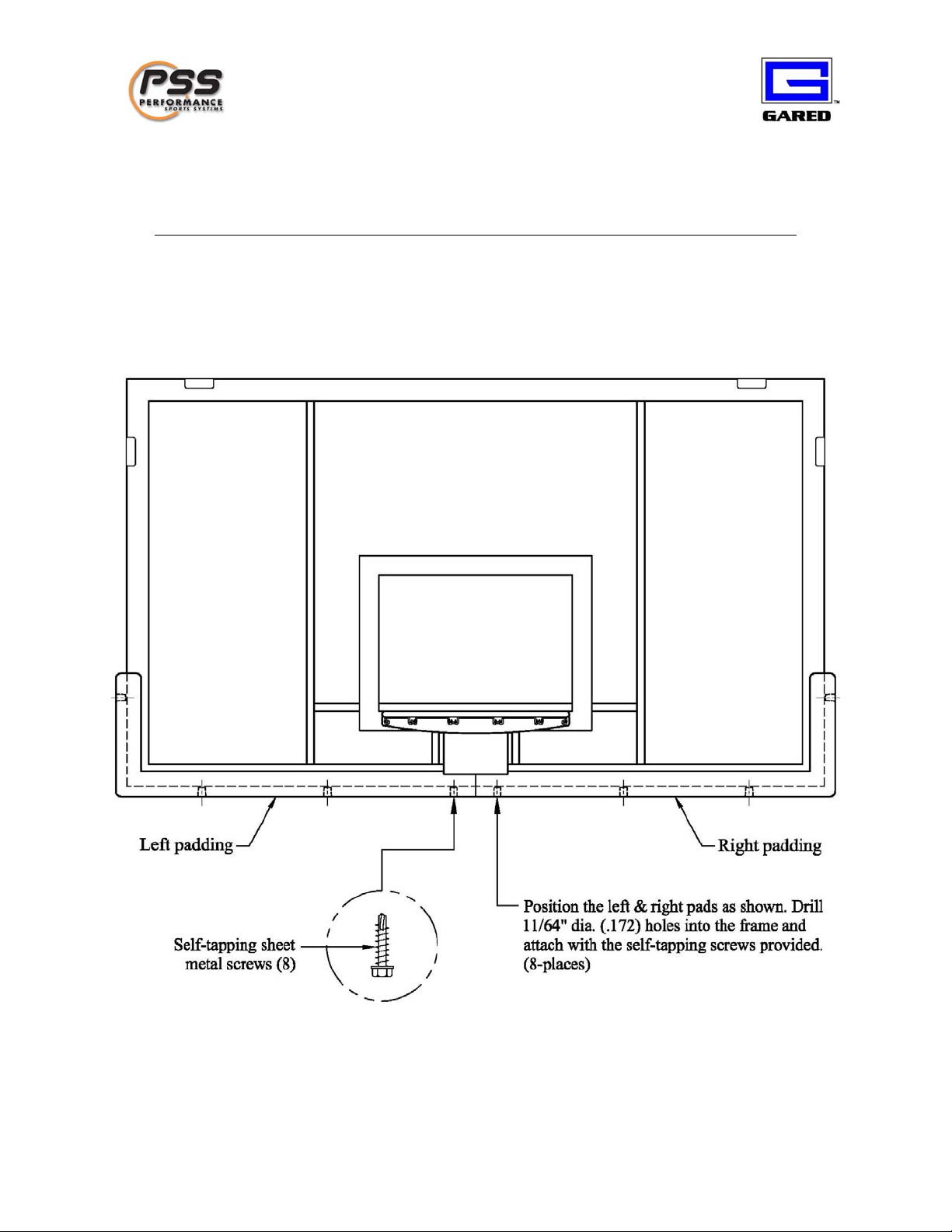
The following illustration shows how to attach the LSCE72 Pro Mold
Recreational Backboard Padding (if purchased). The padding may be
attached before or after the backboard has been mounted in final position.

Elite Pro I & II Adjustable Basketball System
13
The following pages give step by step instructions to complete
the assembly of the GP10 Adjustable Basketball System. Follow the
steps shown below to assemble the unit safely and in the proper order.

Elite Pro I & II Adjustable Basketball System
14
STEP 1: Assemble the actuator brackets as shown.

Elite Pro I & II Adjustable Basketball System
15
STEP 2: Attach the lower support arms as shown in the illustration below.
*Note: Use as much help as is needed to complete this process safely.

Elite Pro I & II Adjustable Basketball System
16
STEP 3: Attach the bottom of the height adjustment actuator to the anchor plates
and the top to the end of the lower support arms as shown in the illustration below.

Elite Pro I & II Adjustable Basketball System
17
STEP 4: Attach the upper pivot arms as shown in the illustration below.

Elite Pro I & II Adjustable Basketball System
18
STEP 5: Attach the backboard to the upper and lower extension arms.
You will need at least three strong men with ladders to complete this operation.
*Helpful hint* Working out of the bed of a truck may be easier than using ladders.
Make sure that you have enough help to complete this operation safely!
This manual suits for next models
3
Table of contents


