TW TDI HV Series User manual

user's manual
dry coolers
INDUSTRIAL TYPE DRY COOLERS
TDI HV SERIES
TDI H
TDI V
TDI W SERIES
TDI W

i
Table of contents
1. Technical Information ......................................................................................................... 1
1.1. Coils Information ......................................................................................................... 1
1.2. Tool Intented Use ........................................................................................................ 1
1.3. Working conditions ..................................................................................................... 1
1.4. Fan Information ........................................................................................................... 2
2. Transport and Storage ......................................................................................................... 2
2.1. Transport ..................................................................................................................... 2
2.2. Storage......................................................................................................................... 3
3. Installation and Location ..................................................................................................... 4
3.1. Installation ................................................................................................................... 4
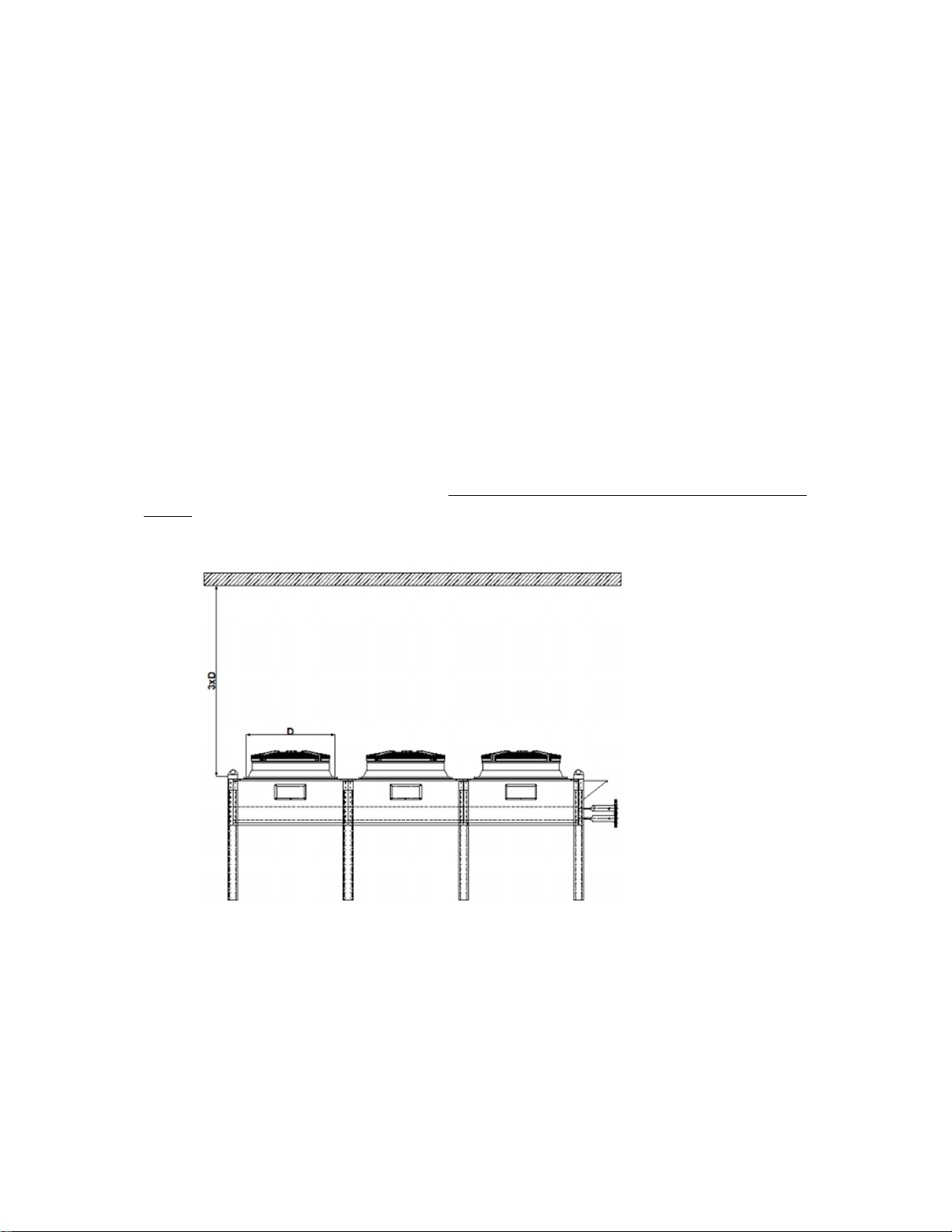
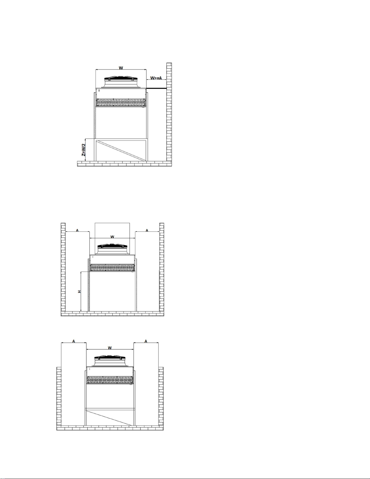
3.1.1. Horizontal Use of Products .................................................................................... 4
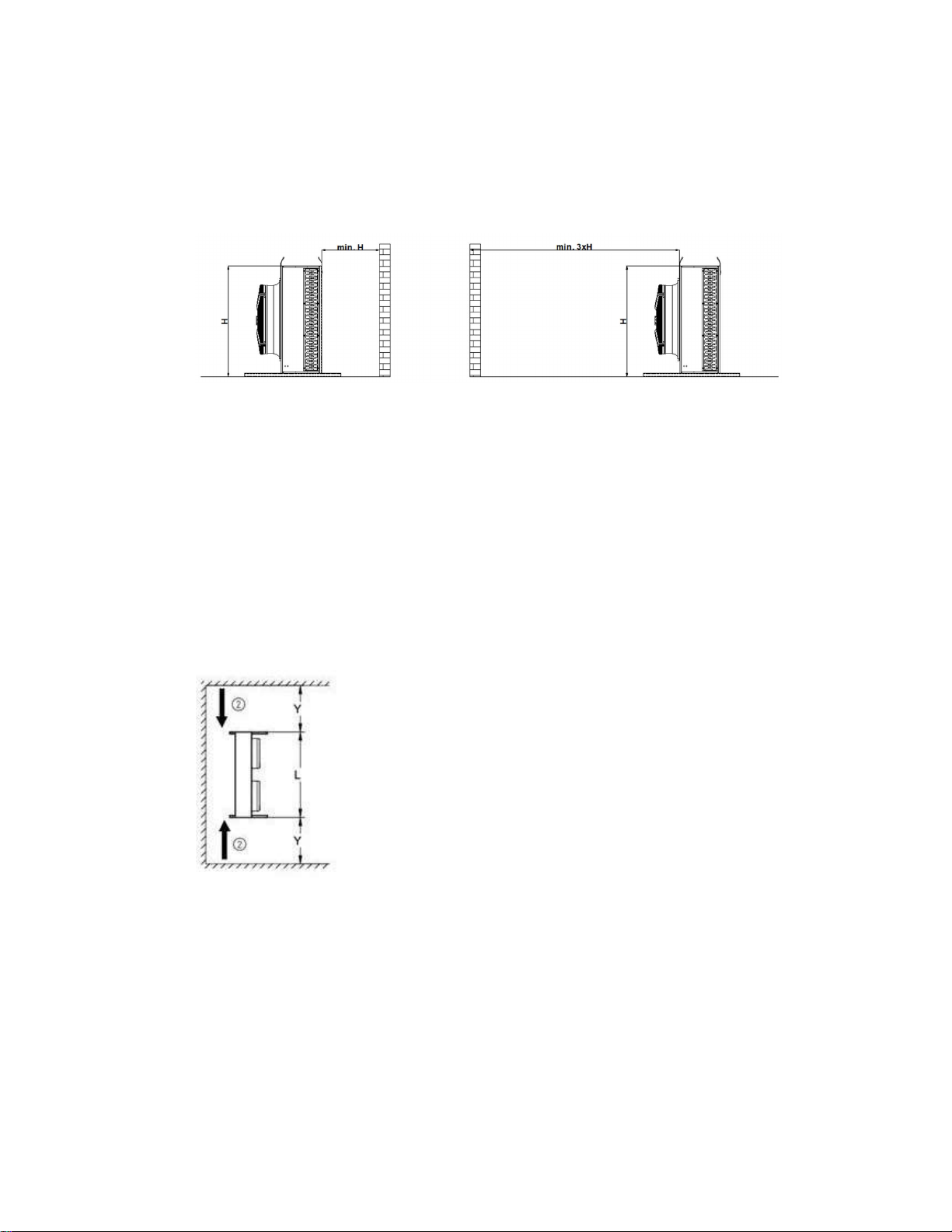
3.1.2. Vertical Use of Products ........................................................................................ 7
3.2. Installation and Assembly ............................................................................................ 8
3.2.1. Leg Installation ...................................................................................................... 8
3.3. Test and Final Control .................................................................................................. 8
4. First Run ............................................................................................................................... 8
5. Maintenance and Cleaning .................................................................................................. 9
5.1. Maintenance of Fans ................................................................................................... 9
5.2. Checking the Unit Battery Section ............................................................................... 9
6. Troubleshooting ................................................................................................................ 10
7. Electrical Wiring Diagrams ................................................................................................. 11
7.1. Fan Connection .......................................................................................................... 11

Sayfa 1 / 12
1. Technical Information
1.1. Coils Information
Standard designs of the product are designed as aluminum fins on copper pipes.
As a standard lamella spacing, 2,1mm - 2,5mm is designed.
In order to increase efficiency, a staggered pipe array has been made.
The faucet is made of aluminum cover on galvanized sheet metal to prevent mirror cuts
and to increase strength.
1.2. Tool Intented Use
Chemical, plastic, Energy etc. It is used in facilities that need process water cooling.
The basic working principle is to transfer the heat load of the hot return water to the air
by means of fans and to reduce its temperature.
Capacity standards for dry cooler are defined for 34% ethylene glycol ratio by volume
according to TS EN 1048 standard. (Heat Exchangers-Air Cooled Liquid Coolers "Dry
Coolers"-Test Methods For Establishing the Performance).
1.3. Working conditions
In order to choose a Dry Cooler, the following criteria must be answered first.
Determination of water inlet and desired water outlet temperature,
Determining the amount of water to be cooled,
Determining the required cooling capacity,
Determination of device dimensions,
maximum allowed in the working environment. Determining the sound level.
Determination of the desired energy class,
Determination of fan operating temperature,

Sayfa 2 / 12
1.4. Fan Information
High efficiency Rosenberg, EBM or equivalent fans should be used.
Axial fans working in the suction direction are used for the Industrial Condensers specified
in this manual.
Voltage value for single-phase fans : 220V / 50Hz.
Voltage value for three-phase fans : 400V / 50Hz.
Three-phase fans with star-delta connection option to operate at two different speeds.
All motors have internal protection thermistors. Motor protection class IP 54; insulation
class is F.
The allowable operating temperature range is from -40°C to +50°C / + 65°C.
(*1) Thermoway reserves the right to use equivalent fans of different companies.
(*2) Fans should be operated for 2 to 4 hours per month during long-term storage and system
downtime.
2. Transport and Storage
2.1. Transport
Before receiving the product, it should be checked that there is no damage to the product
or its packaging.
Vibrations generated during transportation may cause damage to the device. After the
product is unloaded, the delivery pressure control should be done.
If any damage is detected, THERMOWAY A.Ş. company should be informed.
The following instructions and safety rules must be followed while the product is being
transported.
Carrying out by a competent and certified personnel,
Using equipment with sufficient carrying capacity,
Making connections from the transport points specified on the device,
Equal weight distribution should be provided at the transport points.

Sayfa 3 / 12
If the desired angle cannot be achieved with a single rope mechanism in the product, it is
necessary to carry it with the equipment in the image.
If the product is to be transported by forklift, check that the forklift blades are lifted in the
correct direction and with the necessary clearance so that they do not damage the device.
2.2. Storage
tore the product in its package to protect it from unsuitable weather conditions and
environmental effects.
If the product is to be stored for a long time in a humid environment, the condensed water
vapor formed may cause mold on copper and lamella surfaces, so it should be removed
from the environment. run the fans for at least 4 hours every month.
When storing products, avoid stacking them according to the type of packaging.

Sayfa 4 / 12
3. Installation and Location
3.1. Installation
In order for the product to work efficiently, there should be no obstacles affecting the air
suction and discharge.
Appropriate conditions for device placements are given in the following headings.
(*) It should be kept away from heat source or devices blowing high temperature air near the
device.
3.1.1. Horizontal Use of Products
If the product is to be used horizontally, there must be no obstacle to prevent the flow in the
direction of air blowing. If there is an obstacle, it should be at least distance 3 times the diameter of
the fan in order not to create back pressure in the system, and if possible, an air blowing channel
should be made by giving an appropriate angle.
When placing the product, it is necessary to leave a distance of at least as much as the leg
space from all four sides in order not to prevent the air flow around and to provide comfortable
maintenance, cleaning and repair conditions.

Sayfa 5 / 12
In some cases, there may be cases where one side of the device is adjacent to the wall. In such
cases, it is beneficial to build a chassis with a height of at least half the width of the device under the
device and leave a distance of at least 1.5 times the leg space from the 3 sides.

Sayfa 6 / 12
there is a certain opening between the wall and the device, it is useful to close it as in the figure
below so that the air flow is not bypassed.
If the device is located in a hollow environment:
To prevent fan air bypass, the air diverter must be adjusted to the level of the pit. Or the device
should be raised with an additional chassis.
If an air diverter is to be used, its length should
not exceed the diameter of the fan.
Distance A must be greater than W/2
H distance must be greater than A*0.7
If an upgrade was made with a chassis;
Dimension A must be greater than W/2

Sayfa 7 / 12
3.1.2. Vertical Use of Products
If the products are to be used vertically,
distances that should be between it and the surrounding wall are indicated in the pictures.
In addition, if the device is to be placed in an area surrounded by a wall;
The Y distance must be at least L*0.5.
In cases where the received devices must face back to back;

Sayfa 8 / 12
3.2. Installation and Assembly
3.2.1. Leg Installation
Care should be taken to use appropriate equipment while mounting the feet . Regardless, care
must be taken not to use parts, if additions are to be made, to use parts with the same properties.
3.3. Test and Final Control
Failure to perform pre-start testing and final inspection could result in serious injury or death.
What to do is outlined below.
Check the availability of the device location Make sure the rules in the Location header
are applied.
Identify and eliminate factors that would interfere with adequate airflow.
Check that the electrical connections are complete and under protection.
Check the suitability of the pipeline connected to the system, its support from the
necessary points and its direction.
Check the welding points of the pipe connections for the last time.
If the product is under the sun or in a place where it will be exposed to constant rain,
it is useful to take it under protection.
Check whether there are any residual packaging parts that will prevent the air flow on
the product air suction and discharge sides.
4. First Run
Make sure the Test and Final check procedure is complete.
When refrigerant gas is supplied to the system, perform leak control with a suitable
leak control device.
Remove any vibration detected in system operation.
Check the running direction of the fans.
Check the vibration of the fans.
Make sure all fans are activated.
Monitor system pressure.
If possible, provide observation of the system for the first 48 hours.

Sayfa 9 / 12
5. Maintenance and Cleaning
For safety purposes before maintenance, the gas in the system should be collected in another
place and the inlet and outlet valves, if any, should be closed to prevent possible serious injuries and
deaths from being disconnected from the system.
Since regular maintenance and cleaning will extend the life of the product, it is necessary to
establish and follow the maintenance and cleaning period.
5.1. Maintenance of Fans
Regular maintenance of fans will prevent possible hazards and prevent decreasing in device
efficiency.
Sample periodic maintenance chart is attached below.
Vibrating Operation Control of Fans
Sound control to detect possible malfunctions
3 Months
Corrosion control of the connecting bolts of the fans (*) 6 Months
Deformation of fan blades or protection wire (*) 6 Months
Detection of possible deformations in fan electrical cables (*) 6 Months
(*) Closing the electrical line to the fans during the controls will prevent possible serious
injuries and deaths.
5.2. Checking the Unit Battery Section
Intermittent maintenance and inspection of the battery section will prevent possible hazards
and device efficiency.
Sample periodic maintenance chart is attached below.
Cleaning of the lamella surface and control of dents 2 Months
Cleaning the lamella surface with pressurized water. (*) 6 Months
Control of the system with a leak detector to prevent leaks that may occur due to possible
vibration.
6 Months
Control of corrosion or deformation in connecting pipes 6 Months

Sayfa 10 / 12
(*)Cleaning the lamella surface should be done against the direction of air suction. For this, the
fans must be disconnected from the electrical connection and removed. Example of cleaning with
water is given below.
Check the First Run procedure after all maintenance work is finished
6. Troubleshooting
Possible Problems Reasons Solutions
Fans Not Working
There may be a problem with
the electrical connection
Check Electrical Connection
Fan blade jamming Identify possible mechanical
failures.
Loud Fan Sound Fan Motor has failed Fan Needs Renewal.
Vibration Fan sourced Investigating the cause of
vibration of the fan, checking the
connecting bolts, balancing or
replacing the fan with a new one.
Pipeline welded Recalculating the diameters used
on the line, checking the pipe
support points
Insufficient Unit Capacity fan sourced Check that the fans are working
properly
Battery surface is dirty Cleaning the battery surface and
removing substances that will
block the air flow
Possible Pressure Equipment
Failure
Defective equipment should be
detected if any
Possible Gas Leak Leak detection should be done

Sayfa 11 / 12
7. Electrical Wiring Diagrams
7.1. Fan Connection
HIGH SPEED CONNECTION
LOW SPEED CONNECTION
This manual suits for next models
3
Table of contents
Popular Freezer manuals by other brands

ZANKER
ZANKER ZKK8414K user manual

Bosch
Bosch KDD Series Operating and installation instructions

Beko
Beko BFFD4577 Instructions for use

Kenmore
Kenmore 461.27432 Owner's use and care guide

HAEGER
HAEGER KS-100C manual

Electrolux Professional
Electrolux Professional Kelvinator KCHGF24 Service and installation manual