Ubiquiti arFber AF-5XHD User manual

18.02.2020 AF-5XHD Quck Start Gude
https://dl.ubnt.com/qsg/AF-5XHD/AF-5XHD_EN.html 1/29
a
rF
ber AF-5XHD GPS Antenna Mount External GPS Antenna
Metal Strap Z
p T
es (Qty. 2) Un
versal Bracket
IP67 Upgrade K
t
(Vent and Gasket) G
gab
t PoE (24V, 1A) w
th
Mount
ng Bracket Power Cord
Package Contents
Antenna Compat
b
l
ty
The a
rF
ber AF-5XHD rad
o
s des
gned for use w
th the follow
ng a
rF
ber X antenna
models:
AF-5G23-S45
AF-5G30-S45
AF-5G34-S45
The AF-5XHD can also operate w
th the follow
ng RocketD
sh™ antenna models:
RD-5G30*
AF-5XHD Qu
ck Start Gu
de
18.02.2020 AF-5XHD Quck Start Gude
https://dl.ubnt.com/qsg/AF-5XHD/AF-5XHD_EN.html 2/29
RD-5G34*
* Requ
res Un
versal Bracket (
ncluded) or AF-5G-OMT-S45 Convers
on K
t (not
ncluded).
Installat
on Requ
rements
Clear l
ne of s
ght between a
rF
ber rad
os
Clear v
ew of the sky for proper GPS operat
on
Vert
cal mount
ng or
entat
on
Mount
ng po
nt:
At least 1 m below the h
ghest po
nt on the structure
For tower
nstallat
ons, at least 3 m below the top of the tower
Ground w
res – m
n. 10 AWG (5 mm ) and max. length: 1 m. As a safety precaut
on,
ground the a
rF
ber rad
o to grounded masts, poles, towers, or ground
ng bars.
WARNING:
Fa
lure to properly ground your a
rF
ber rad
o w
ll vo
d your
warranty.
(Recommended) 2 Outdoor G
gab
t PoE surge protectors
Note:
For gu
del
nes about ground
ng and l
ghtn
ng protect
on, follow your
local electr
cal regulatory codes.
Outdoor, sh
elded Category 6 (or above) cabl
ng and sh
elded RJ-45 connectors are
requ
red for all w
red Ethernet connect
ons.
Hardware Overv
ew
2
AF-5XHD Qu
ck Start Gu
de
18.02.2020 AF-5XHD Quck Start Gude
https://dl.ubnt.com/qsg/AF-5XHD/AF-5XHD_EN.html 3/29
a
rF
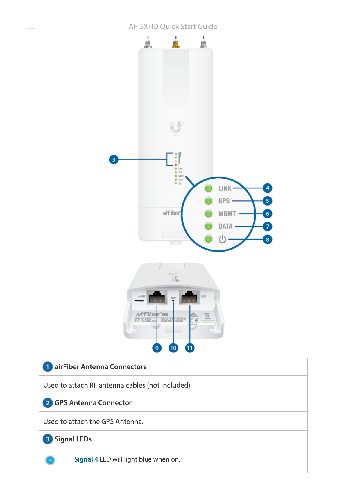
ber Antenna Connectors
GPS Antenna Connector
S
gnal LEDs
Used to attach RF antenna cables (not
ncluded).
Used to attach the GPS Antenna.
S
gnal 4
LED w
ll l
ght blue when on.
AF-5XHD Qu
ck Start Gu
de
18.02.2020 AF-5XHD Quck Start Gude
https://dl.ubnt.com/qsg/AF-5XHD/AF-5XHD_EN.html 4/29
L
nk LED
GPS LED
S
gnal 3
LED w
ll l
ght green when on.
S
gnal 2
LED w
ll l
ght yellow when on.
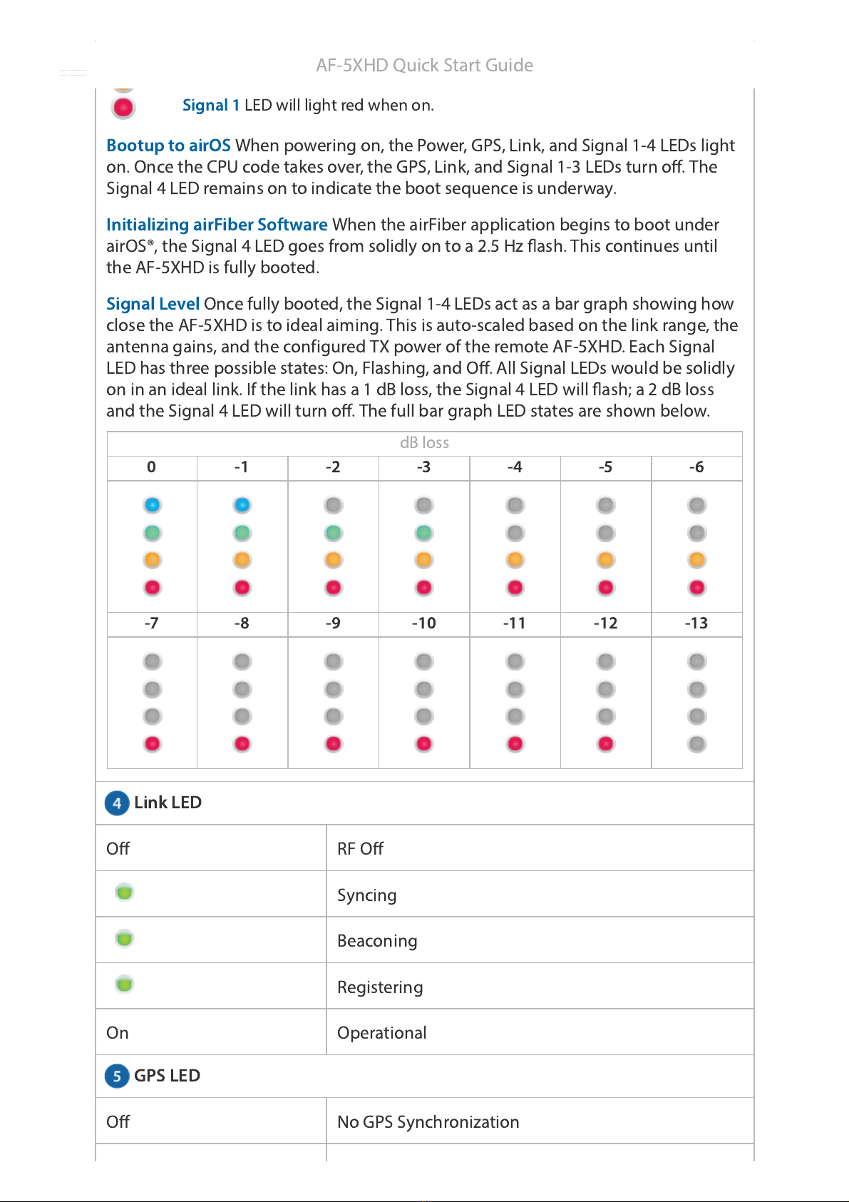
S
gnal 1
LED w
ll l
ght red when on.
Bootup to a
rOS
When power
ng on, the Power, GPS, L
nk, and S
gnal 1-4 LEDs l
ght
on. Once the CPU code takes over, the GPS, L
nk, and S
gnal 1-3 LEDs turn off. The
S
gnal 4 LED rema
ns on to
nd
cate the boot sequence
s underway.
In
t
al
z
ng a
rF
ber Software
When the a
rF
ber appl
cat
on beg
ns to boot under
a
rOS®, the S
gnal 4 LED goes from sol
dly on to a 2.5 Hz ash. Th
s cont
nues unt
l
the AF-5XHD
s fully booted.
S
gnal Level
Once fully booted, the S
gnal 1-4 LEDs act as a bar graph show
ng how
close the AF-5XHD
s to
deal a
m
ng. Th
s
s auto-scaled based on the l
nk range, the
antenna ga
ns, and the conf
gured TX power of the remote AF-5XHD. Each S
gnal
LED has three poss
ble states: On, Flash
ng, and Off. All S
gnal LEDs would be sol
dly
on
n an
deal l
nk. If the l
nk has a 1 dB loss, the S
gnal 4 LED w
ll ash; a 2 dB loss
and the S
gnal 4 LED w
ll turn off. The full bar graph LED states are shown below.
dB loss
0 -1 -2 -3 -4 -5 -6
-7 -8 -9 -10 -11 -12 -13
Off RF Off
Sync
ng
Beacon
ng
Reg
ster
ng
On Operat
onal
Off No GPS Synchron
zat
on
AF-5XHD Qu
ck Start Gu
de
18.02.2020 AF-5XHD Quck Start Gude
https://dl.ubnt.com/qsg/AF-5XHD/AF-5XHD_EN.html 5/29
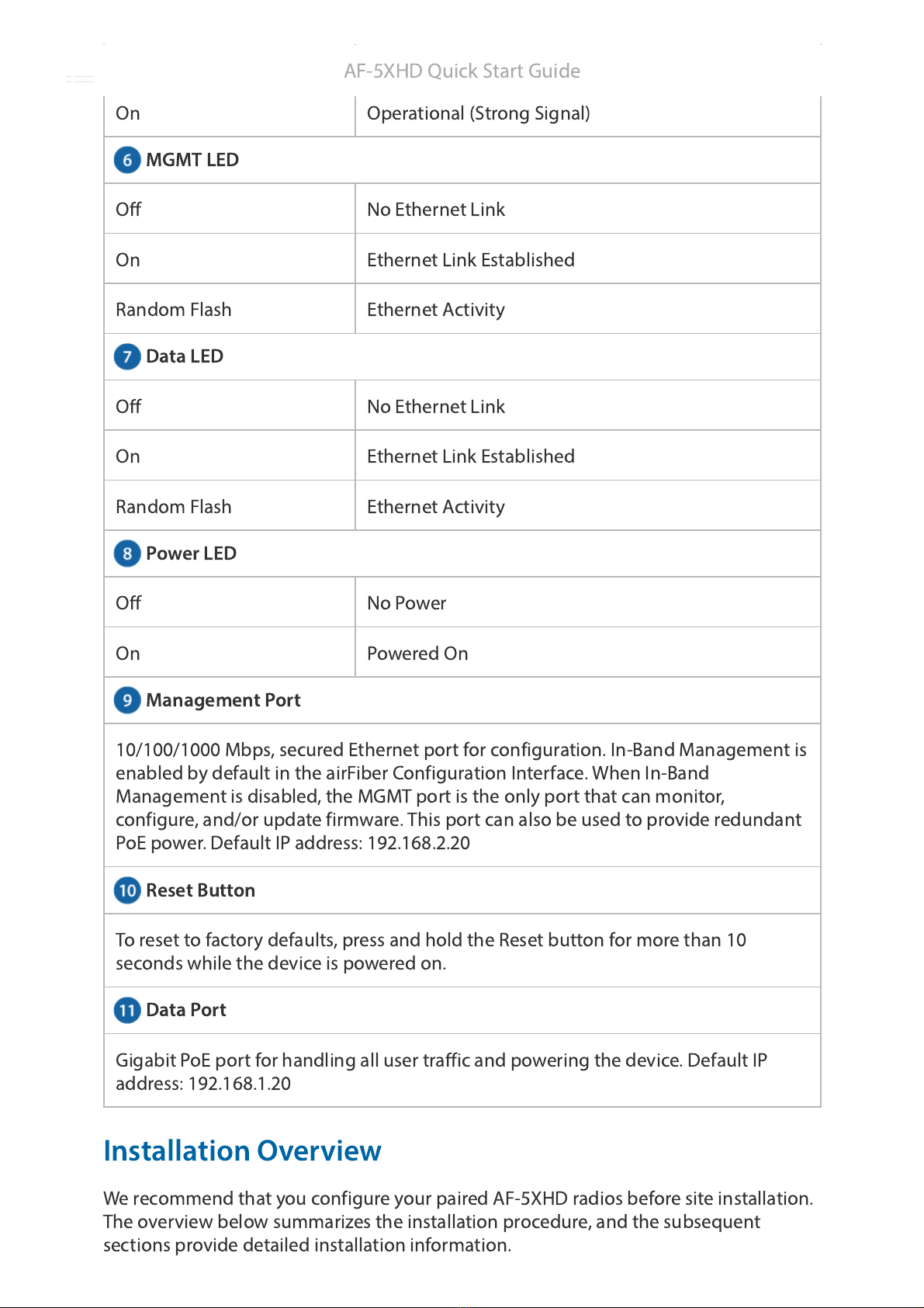
MGMT LED
Data LED
Power LED
Management Port
Reset Button
Data Port
Non-Operat
onal (Weak S
gnal)
On Operat
onal (Strong S
gnal)
Off No Ethernet L
nk
On Ethernet L
nk Establ
shed
Random Flash Ethernet Act
v
ty
Off No Ethernet L
nk
On Ethernet L
nk Establ
shed
Random Flash Ethernet Act
v
ty
Off No Power
On Powered On
10/100/1000 Mbps, secured Ethernet port for conf
gurat
on. In-Band Management
s
enabled by default
n the a
rF
ber Conf
gurat
on Interface. When In-Band
Management
s d
sabled, the MGMT port
s the only port that can mon
tor,
conf
gure, and/or update f
rmware. Th
s port can also be used to prov
de redundant
PoE power. Default IP address: 192.168.2.20
To reset to factory defaults, press and hold the Reset button for more than 10
seconds wh
le the dev
ce
s powered on.
G
gab
t PoE port for handl
ng all user traff
c and power
ng the dev
ce. Default IP
address: 192.168.1.20
Installat
on Overv
ew
We recommend that you conf
gure your pa
red AF-5XHD rad
os before s
te
nstallat
on.
The overv
ew below summar
zes the
nstallat
on procedure, and the subsequent
sect
ons prov
de deta
led
nstallat
on
nformat
on.
AF-5XHD Qu
ck Start Gu
de


