Operate the motor for approximately 2 hours at
the maximum desired load. Measure the surface
temperature of the motor on the casting opposite
the pipe ports. The maximum surface temperature
listed on the motor is for normal environmental
and installation conditions. For most air motors,
the maximum surface temperature should not
exceed 275ºF/135ºC. Do not continue to operate
the motor if the measured surface temperature
exceeds temperature listed on the motor. If your
measured temperature does exceed listed value,
consult with your Gast Distributor/Representative
for a recommendation.
MAINTENANCE
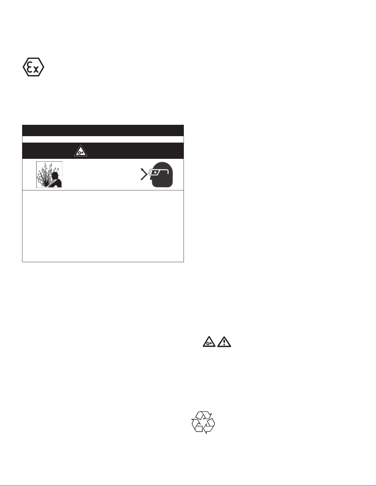
m WARNING
Injury Hazard
Disconnect air supply and vent all air lines.
Wear eye protection when flushing this product.
Air stream from product may contain solid or liquid materi-
al that can result in eye or skin damage.
Flush this product in a well ventilated area.
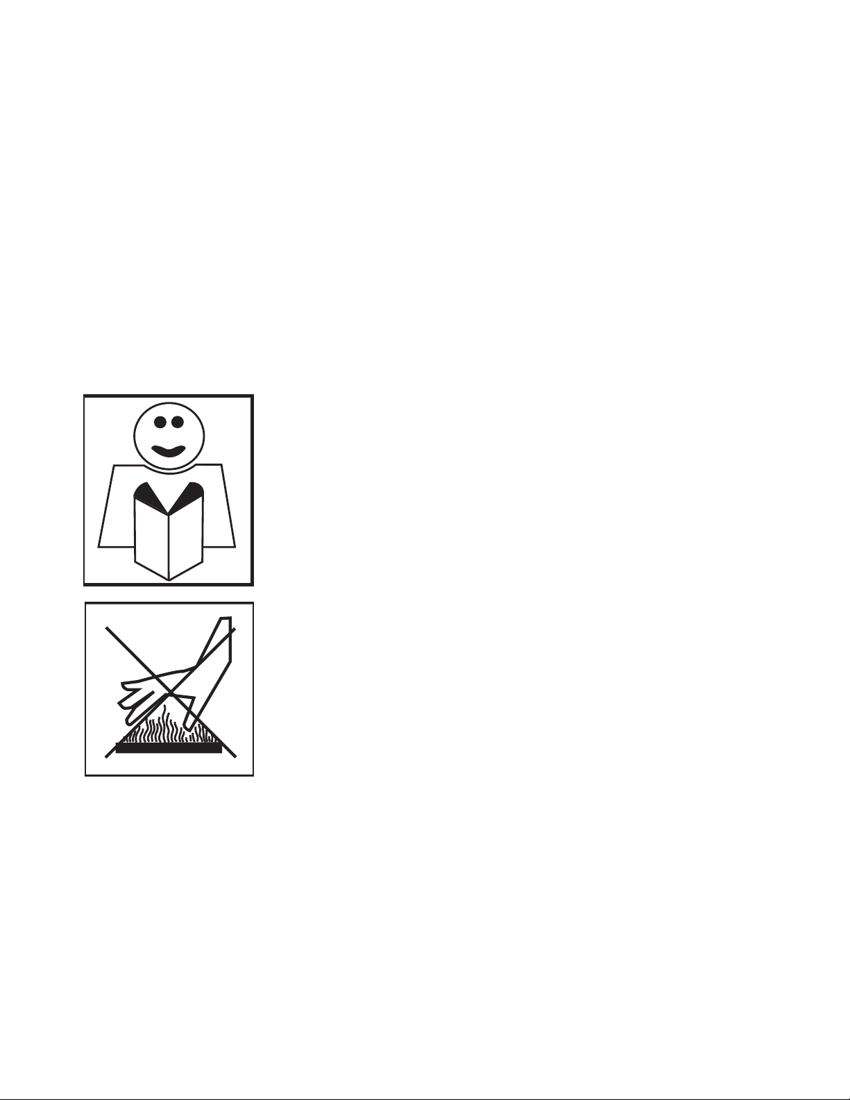
Do Not use kerosene or other combustible solvents to
flush this product.
Failure to follow these instructions can result in eye injury
or other serious injury.
It is your responsibility to regularly inspect and make
necessary repairs to this product in order to maintain proper
operation.
For Lubricated Operation
Use Gast #AD220 or a detergent SAE #10 automotive engine oil for
lubricating. Lubricating is necessary to prevent rust on all moving
parts. Excessive moisture in air line may cause rust or ice to form in
the mufer when air expands as it passes through the motor. Install
a moisture separator in the air line and an after cooler between
compressor and air receiver to help prevent moisture problems.
Manual Lubrication
Shut the air motor down and oil after every 8 hours of operation.
Add 10-20 drops of oil to the air motor intake port.
Automatic Lubrication
Adjust inline oiler to feed 1 drop of oil per minute for high speed
or continuous duty usage. Do not overfeed oil or exhaust air may
become contaminated. Check intake and exhaust lters after rst
500 hours of operation. Clean lters and determine how frequently
lters should be checked during future operation. This one
procedure will help assure the motor’s performance and service life.
Flushing
Flushing this product to remove excessive dirt, foreign particles,
moisture or oil that occurs in the operating environment will help to
maintain proper vane performance. Flush the motor if it is operating
slowly or inefciently.
Use only Gast #AH255B Flushing Solvent. DO NOT use
kerosene or ANY other combustible solvents to flush this
product.
1. Disconnect air line and mufer.
2. Add ushing solvent directly into motor. If using liquid solvent,
pour several tablespoons directly into the intake port. If using
Gast #AH255B, spray solvent for 5-10 seconds into intake
port.
3. Rotate the shaft by hand in both directions for a few minutes.
4. You must wear eye protection for this step. Cover exhaust with
a cloth and reconnect the air line.
5. Restart the motor at a low pressure of approximately 10 psi/
0.7 bar until there is no trace of solvent in the exhaust air.
6. Listen for changes in the sound of the motor. If motor sounds
smooth, you are nished. If motor does not sound like it is
running smoothly, installing a service kit will be required (See
“Service Kit Installation”).
Check that all external accessories such as relief valves or
gauges are attached and are not damaged before operating
product.
Cleaning the sound absorber.
1. Remove the sound absorber (for non-lubricated operation,
inspect mufer every 90 days. To avoid excessive clogging of
mufer element, change frequently).
2. Clean the felt lter.
3. You must wear eye protection for this step. For lubricated
operation, add 3-4 drops of oil.
4. Check the air compressor.
5. Listen for changes in the sound of the motor. If motor sounds
smooth, you are nished. If motor does not sound like it running
smoothly, installing a service kit will be required (See “Service
Kit Installation”).
Shutdown.
It is your responsibility to follow proper shutdown procedures
to prevent product damage.
1. Turn off air intake supply.
2. Disconnect air supply and vent all air lines.
3. Disconnect air lines.
4. Remove air motor from connecting machinery.
5. Remove the mufer.
6. Wear eye protection. Keep away from air
stream. Use clean, dry air to remove condensation from the
inlet port of the motor.
7. For lubricated operation, add a small amount of oil into the
intake port. Rotate shaft by hand several times to distribute oil.
8. Plug or cap each port.
9. Coat output shaft with oil or grease.
10. Store motor in a dry environment.
Disposal (Please note current regulations) Parts of the
air motor or air powered gear motor, shafts, cast iron
or aluminum castings, gear wheels as well as rolling
contact bearings may be recycled as scrap metal.
Revision 11/3/2021
6