unicraft TWG 20 User manual

TWG 20
TWG 80 TWG 150
Operating Instructions
Part Washing Unit
TWG 20, TWG 80, TWG 150
TWG-SERIES

2TWG-Series | Version 1.01
Imprint
Product identification
Part Washing Unit Item number
TWG 20 6220020
TWG 80 6220080
TWG 150 6220150
Manufacturer
Stürmer Maschinen GmbH
Dr.-Robert-Pfleger-Str. 26
D-96103 Hallstadt
Fax: 0049 (0) 951 96555 - 55
E-Mail: [email protected]
Internet: www.unicraft.de
Indications regarding the operating instructions
Genuine operating instructions
Edition: 20.01.2020
Version: 1.01
Language: English
Author: ES
Indications regarding the copyright
Copyright © 2020 Stürmer Maschinen GmbH, Hallstadt,
Germany.
The contents of these operating instructions are the sole
property of the company Stürmer. Passing on as well as
copying of this document, the use and distribution of its
content are prohibited if not explicitly permitted. Contra-
ventions are liable to compensation.
Subject to technical modifications and error.
Content
1 Introduction .............................................................3
1.1 Copyright............................................................ 3
1.2 Customer service................................................ 3
1.3 Limitation of liability ............................................ 3
2 Safety........................................................................3
2.1 Symbol explanation ............................................ 3
2.2 Responsibility of the operator............................. 4
2.3 Personnel requirements...................................... 4
2.4 Personal protective equipment........................... 5
2.5 Safety labels ....................................................... 5
2.6 Safety instructions .............................................. 5
3 Intended Use............................................................6
4 Technical Data.........................................................6
4.1 Type plate........................................................... 6
5 Transport, packaging, storage...............................7
6 Description of device..............................................7
7 Assembly, Set up and Connecting ........................8
7.1 Assembly............................................................ 8
7.2 Electrical connection .......................................... 9
8 Commissioning .....................................................10
9 Care, maintenance and servicing/ repair ............11
9.1 Care by cleaning .............................................. 11
9.2 Maintenance and repair/servicing.................... 11
9.3 Troubleshooting................................................ 12
10 Disposal, Recycling of used devices ................12
10.1 Decommission................................................ 12
10.2 Disposal via municipal collection points ........ 12
10.3 Disposal of lubricants..................................... 12
11 Spare parts...........................................................13
11.1 Ordering spare parts ...................................... 13
11.2 Spare parts drawings ..................................... 14
12 Electrical circuit diagram....................................15
13 EU Declaration of Conformity ............................16

Introduction
TWG-Series | Version 1.01 3
1Introduction
You have made a good choice by purchasing the UNI-
CRAFT part washing unit.
Thoroughly read the operating instructions before commissio-
ning the part washing unit.
This informs about the proper commissioning, the inten-
ded use as well as the safe and efficient operation and
maintenance of the part washing unit.
The operating instructions are part of the part washing
unit. It must always be stored at the place of use of the
part washing unit. In addition, the local accident preven-
tion regulations and general safety regulations apply for
the area of application of the part washing unit.
Illustrations in this operating manual serve the general
understanding and may deviate from the actual design.
1.1 Copyright
The contents of this manual are protected by copyright.
Their use is permitted when using the machine. Any
further use is not permitted without the written permis-
sion of the manufacturer.
We hereby apply for trademark, patent and design
rights to protect our pro-ducts, if this is possible in indi-
vidual cases. We vigorously oppose any infringement of
our intellectual property.
1.2 Customer service
Please contact your dealer if you have questions conce-
ring your product or if you need technical advice. They
will help you with specialist information an expert ad-
vice.
Germany:
Stürmer Maschinen GmbH
Dr.-Robert-Pfleger-Str. 26
D-96103 Hallstadt
Repair service:
Fax: 0049 (0) 951 96555-111
Email: service@stuermer-maschinen.de
Internet: www.unicraft.de
Spare parts orders:
Fax: 0049 (0) 951 96555-119
Email: ersatzteile@stuermer-maschinen.de
We are always interested in valuable experience and
knowledge gained from using the application-which
then could be shared and be valuable to develop our
products even further.
1.3 Limitation of liability
All information and notes in these operating instructions
were summarised while taking applicable standards
and rules, the state-of-the-art technology and our long-
term knowledge and experiences into consideration.
In the following cases the manufacturer is not liable for
damages:
- Non-observance of the operating instructions,
- Inappropriate use
- Use of untrained staff
- unauthorised modifications
- technical changes
- Use of not allowed spare parts
The actual scope of delivery may deviate from the ex-
planations and presentations described here in case of
special models, when using additional ordering options
or due to latest technical modifications.
The obligations agreed in the delivery contract, the ge-
neral terms and conditions as well as the delivery condi-
tions of the manufacturer and the legal regulations valid
at the time of the conclusion of the contract apply.
2 Safety
This section provides an overview of all important safety
packages for the protection of operating personnel as
well as for safe and fault-free operation. Other task-
based safety notes are included in the paragraphs of
the individual phases of life.
2.1 Symbol explanation
Safety instructions
The safety notes in these operating instructions are
high- lightet by symbols. The safety notes are intro-
duced by signal words which express the concern of
the risk. .
ATTENTION!
This combination of symbol and signal word indica-
tes a potentially hazardous situation which, if not
avoided, could result in property damage and env-
ironmental damage.
DANGER!
This combination of symbol and signal words indi-
cates an imminently dangerous situation which may
lead to death or severe injuries if they are not
avoided.

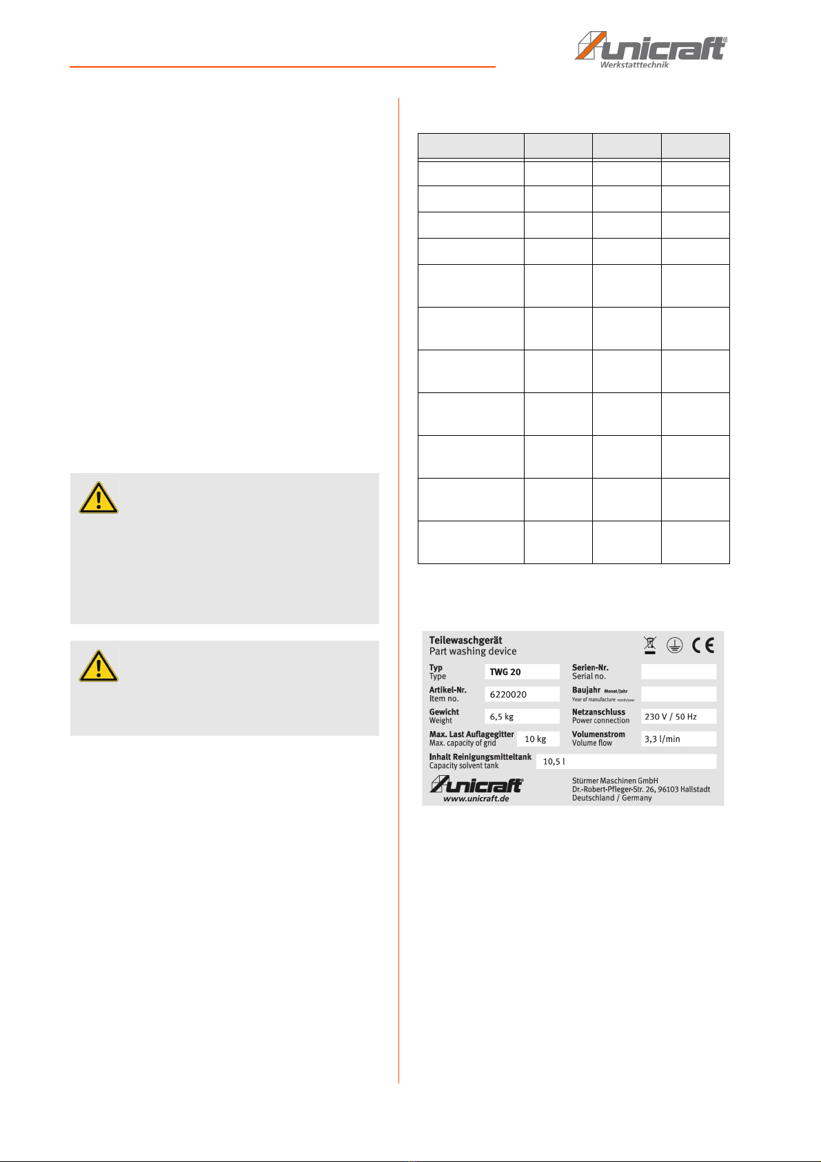
4TWG-Series | Version 1.01
Safety
Tips and recommendations
It is necessary to observe the safety notes written in
these operating instructions in order to reduce the risk of
personal injuries and damages to property.
2.2 Responsibility of the operator
The operator is the person who operates the machine
for commercial or economic purposes himself or leaves
it to a third for use or application and bears the legal
product responsibility for the protection of the user, per-
sonnel or third during operation.
If the part washing unit is used for commercial pur-
poses, the operating company of the the part washing
unitmust comply with the legal working safety regula-
tions. Therefore, the safety notes in this operating man-
ual, as well as the safety, accident prevention and envi-
ronment protection regulations applying for the area of
application of the the part washing unit must be met.
The following applies in particular:
- The operator must obtain information about the ap-
plicable occupational safety regulations and, in a
risk assessment, must also determine additional
hazards resulting from the special working conditi-
ons at the place of use of the machine. He must
implement these in the form of operating instructi-
ons for the operation of the machine.
- The operator must check during the entire period
of use of the machine whether the operating in-
structions he has prepared comply with the cur-
rent state of the regulations and adjust them if
necessary.
- The operator must clearly regulate and determine
the responsibilities for installation, operation,
troubleshooting, maintenance and cleaning.
- The operator must ensure that all persons hand-
ling the machine have read and understood this
manual. In addition, he must train the staff at regu-
lar intervals and inform them about the dangers.
- The operator must provide the personnel with the
necessary protective equipment and bind the
wearing of the required protective equipment.
Furthermore, the operator is responsible for ensuring
that the machine is always in perfect technical condi-
tion. Therefore, the following applies:
- The operator must ensure that the maintenance in-
tervals described in this manual are observed.
- The operator must have all safety equipment regu-
larly checked for functionality and completeness.
2.3 Personnel requirements
The various tasks described in this manual place diffe-
rent demands on the qualifications of the people entru-
sted with these tasks.
Only persons reliable working procedures can be ex-
pected from, are allowed to perform all works. Persons
the responsiveness of which is affected by e. g. drugs,
alcohol or medication, are not allowed to work with the
machine.
The qualifications of the personnel for the different tasks
are mentioned below:
Operator:
The operator is instructed by the operating company
about the assigned tasks and possible risks in case of
improper behaviour. Any tasks which need to be per-
formed beyond the operation in the standard mode
must only be performed by the operator if it is indicated
in these instructions and if the operating company ex-
pressively commissioned the operator.
WARNING!
This combination of symbol and signal word indica-
tes a potentially dangerous situation. It leads to
death or serious injury if it is not avoided.
CAUTION!
This combination of symbol and signal word indica-
tes a potentially hazardous situation which, if not
avoided, may result in minor or light injuries.
NOTE!
This combination of symbol and signal word indica-
tes a potentially dangerous situation. It can lead to
material and environmental damage if it is not avoi-
ded.
Tips and recommendations
This symbol highlights useful tips, recommendati-
ons and information for efficient and trouble-free
operation.
WARNING!
Danger due to insufficient qualification of persons!
Insufficiently qualified persons can not assess the
risks involved in handling the machine and expose
themselves and others to the risk of serious or fatal
injuries.
- All work should only be carried out by qualified per-
sons.
- Keep inadequately qualified persons out of the
work area.

Safety
TWG-Series | Version 1.01 5
Electrician:
The electrician is due to their professional training,
knowledge and experience as well as knowledge of the
relevant standards and regulations able to work on
electrical systems and independently recognize and
avoid possible dangers. The electrician is specially trai-
ned for the work environment in which he works and
knows the relevant standards and regulations.
Qualified personnel:
Due to their professional training, knowledge and expe-
rience as well as their knowledge of relevant regulations
the specialist staff is able to perform the assigned tasks
and to recognise and avoid any possible dangers them-
selves.
Manufacturer:
Certain works may only be performed by specialist per-
sonnel of the manufacturer. Other personnel is not au-
thorized to perform these works. Please contact our cu-
stomer service for the execution of all arising work.
2.4 Personal protective equipment
The personal protective equipment serves to protect
persons against impairments of safety and health while
working. The staff member has to wear personal protec-
tive equipment while performing different tasks on and
with the machine which are indicated in the individual
paragraphs of these instructions.
The personal protective equipment is explained in the
following paragraph:
2.5 Safety labels
Various safety labels are attached to the part washing
unit, which must be observed and followed.
The safety labels must not be removed. Damaged or mis-
sing safety labels can lead to incorrect handling, perso-
nal injury and damage to property. They must be re-
placed immediately.
If the safety labels are not immediately recognizable
and comprehendible, the part washing unit should be
taken out of service until new safety labels have been
made.
The following safety labels and symbols are attached:
Fig. 1: Safety labels on the part washing unit
2.6 Safety instructions
- Keep the work area clean and tidy. Untidy work-
places and workbenches increase the risk of acci-
dents and injuries.
- Ensure adequate lighting. The lighting level should be
at least 300 lux.
- Do not smoke in the near of the part washing unit!
Ear protection
The ear protection protects against hearing damage
caused by noise.
Respiratory protection
The respiratory protection protects the respiratory
tract against the ingress of dust and small foreign
bodies.
Eye protection
The protective goggles protect the eyes from flying
parts and liquid splashes.
Protective gloves
The protective gloves protect the hands from sharp-
edged components as well as from friction, abrasi-
ons or deeper injuries.
Safety boots
The safety boots protect the feet against bruising, fal-
ling parts and slipping on slippery surfaces.
Protective clothing
The protective clothing is tight-fitting clothing with
low tear resistance.
Use protective gloves!
DANGER!
Danger to life from electric current!
ALWAYS disconnect the part washing unit from the
power source before servicing or cleaning the unit.

6TWG-Series | Version 1.01
Intended Use
- Do not operate the unit near heat sources such as
radiators, open fire or sparks.
- Do not inhale health-endangering vapours! (Ob-
serve the safety data sheets of the cleaning agent
manufacturer).
- Fill the cleaning agent up to the specified level of
the parts tray.
- Keep children and persons not familiar with the part
washing unit away from their working environment.
- The part washing unit must not be used by persons
with reduced physical, sensory or mental perfor-
mance.
- Never work under the influence of concentration ill-
nesses, fatigue, drugs, alcohol or medication.
- Only use the part washing unit in well-ventilated
rooms.
- Check the device for damage. Damaged parts
should be properly repaired or replaced.
- Only use original spare parts and accessories to
avoid possible hazards and risks of accidents.
3 Intended Use
The part washing unit is designed exclusively for thoro-
ugh cleaning of workpieces with water-based cleaning
solution. The part washing unit is only approved for ope-
ration with suitable cleaning agents and may only be
operated by persons who have been instructed in the
use of the device.
Proper use also includes compliance with all information
in this manual. Any use beyond the intended use or
otherwise is considered misuse.
For structural and technical changes to the part washing
unit, the company Stürmer Maschinen GmbH assumes
no liability.
Claims of any kind due to damage due to improper use are
excluded.
4 Technical Data
4.1 Type plate
Fig. 2: Type plate
ATTENTION!
- Do not pull the cable. Only pull on the plug to dis-
connect it. Keep the cable away from heat sources,
oil and sharp edges.
- Always ensure that the device is switched off at the
ON/OFF switch before inserting the power plug into
the socket.
ATTENTION!
The part washing unit may only be operated with
non-flammable liquids and only with water-based
cleaning agents!
Model TWG 20 TWG 80 TWG 150
Length 430 mm 760 mm 1090 mm
Width / Depth 340 mm 540 mm 540 mm
Height 220 mm 880 mm 890 mm
Weight 6,5 kg 23 kg 42 kg
Supply voltage 230 V/
~50 Hz
230 V/
~50 Hz
230 V/
~50 Hz
Cabine
capacity
20 l 80 l 150 l
Max. weight on
support grille
10 kg 20 kg 40 kg
Speed of
circulation
3,3 l/min 3,3 l/min 3,3 l/min
Minimum sol-
vent capacity
10,5 l 36 l 72 l
Connection
cable length
1,5 m 1,5 m 1,5 m
Absorbed po-
wer drive motor
0,026 kW 0,026 kW 0,026 kW

Transport, packaging, storage
TWG-Series | Version 1.01 7
5 Transport, packaging, storage
Delivery
Check the part washing unit for visible transport da-
mage after delivery. If you discover any damage, imme-
diately report it to the transport company or the dealer..
Transport
The part washing unit must not be stacked on top of
each other. No other objects may be placed on the part
washing unit.
Packaging
All used packaging materials and packaging aids are
recyclable and should be taken to a materials recycling
depot to be disposed of.
The delivery packaging is made of cardboard, so
please dispose carefully by having it chopped up and
given to the recycling collection.
The film is made of polyethylene (PE) and the cushioned
parts of polystyrene (PS). These materials should be
taken to a collection point for recyclable materials or to
the local waste disposal company.
Storage
The part washing unit must be thoroughly cleaned be-
fore storing in a dry, clean, and frost-free environment.
Never store the device filled.
6 Description of device
Illustrations in this operating manual may differ from the
original.
Fig. 3: Part Washing Unit TWG-Series
1 Protective cover
2 Cleaning gun
3 ON/OFF switch
4 Filling container
5 Substructure
6 Base plate
NOTE!
Observe the weight of the device during transport
and lifting. The transport and lifting equipment must
be able to pick up the load.
NOTE!
Protect the device from moisture.
Tips and recommendations
For longer transports, ensure that the corrosion pro-
tection is intact or or renewed if necessary.
NOTE!
The device may never be stored or transported in a
horizontal position or filled!
2
3
4
5
6
1

8TWG-Series | Version 1.01
Assembly, Set up and Connecting
7
Assembly, Set up and Connecting
The part washing unit may only be set up and operated
in dry, well-ventilated rooms.
It must be set up stable on a level and firm ground.
It is important to ensure that there is enough freedom of
movement and sufficient lighting to work.
7.1 Assembly
TWG 20
Step 1: Screw the metal hose onto the connection piece
of the pump outlet (Fig. 4).
Fig. 4: Assembly TWG 20
Step 2: Place the cleaning grille over the brackets on the
tray walls. Ensure that the nozzle of the metal
hose is shaped so that it points downward to-
ward the center of the tray (Fig. 5).
Fig. 5: Assembly TWG 20
Step 3: Fill the tray with a suitable water-based cleaning
solution so that the pump is completely covered
(Fig. 6).
Fig. 6: Assembly TWG 20
Step 4: Connect the part washing unit to a suitable, eart-
hed power outlet whose mains voltage corre-
sponds to the technical data of the device.
Step 5: Set the ON/OFF switch to the "ON" position. The
part washing unit is now ready for use.
TWG 80 and TWG 150
Step 1: With the lid closed, place the tray upside down
on a non-scratch surface (cardboard, carpet,
etc.).
Step 2: Attach each leg to the tray with the provided 6
mm screw set, washers and nuts (Fig. 7A).
Step 3: Fasten the base plate in the middle of the tray
with 2 sets of screws, washers and nuts each
(Fig. 7B).
Step 4: Screw the metal hose onto the pump outlet
(Fig. 7C).
Use protective goggles!
Use protective gloves!
Wear safety boots!
Wear protective clothes!
CAUTION!
Risk of crushing!
There is a risk of injury to fingers and hands if impro-
per work is carried out during assembly of the part
washing unit.
- Note the weight of the parts washing device. Pay
attention to stable supports and support devices.
ATTENTION!
Make sure that the cleaning solution completely cov-
ers the pump, otherwise the pump function is
restricted.

Assembly, Set up and Connecting
TWG-Series | Version 1.01 9
Fig. 7: Assembly TWG 80 and TWG 150
Step 5: Place the 4" x 4" fibrous filter in the perforated fil-
ter cover and slide it under the pump cover
(Fig. 7C)
Step 6: Place the cover on the pump and allow the cover
to engage in the pump housing (Fig. 7C).
Step 7: Return the device to its upright position and
open the cover.
Step 8: Insert the pump power cord through the rectan-
gular opening on the side of the tray. The power
switch is visible through the rectangular opening
(Fig. 8).
Fig. 8: Assembly TWG 80 and TWG 150
Step 9: Check that the drain plug is securely fastened.
Step 10: Place the cleaning grille over the brackets on
the tray walls. Ensure that the nozzle of the metal
hose is shaped so that it points downward to-
ward the center of the tray (Fig. 5).
Step 11: Installation of the supplied cleaning brush (OP-
TIONAL):
The cleaning brush can be placed with the end
of the hose on the nozzle of the metal hose (Fig.
9). Ensure that the nozzle or brush is shaped so
that it points downward toward the center of the
tray.
Fig. 9: Assembly TWG 80 and TWG 150
Step 12: Fill the tray with a suitable water-based
cleaning solution so that the pump is comple-
tely covered (Fig. 6).
Step 13: Connect the part washing unit to a suitable,
earthed power outlet whose mains voltage cor-
responds to the technical data of the device.
Step 14: Set the ON/OFF switch to the "ON" position. The
part washing unit is now ready for use.
7.2 Electrical connection
The wires in the power cord are colored as follows:
Blue: Neutral
Brown: Live
Yellow-Green: Earth
If the colors of the wires in the power cord of this pro-
duct do not match the terminal markings of your plug,
please follow the procedure below.
A
B
C
DANGER!
Danger to life from electric current!
In case of contact with live components, there is an
immediate danger to life through electric shock.
- Work on the electrical system may only be carried
out by qualified electricians.
ATTENTION!
The part washing unit must have a good grounding
to avoid static electricity and sparking.
Check that the mains voltage corresponds to the
voltage specified on the type plate.

10 TWG-Series | Version 1.01
Commissioning
- The blue coloured wire must be connected to the ter-
minal marked N or black.
- The brown wire must be connected to the terminal
marked L or red.
- The yellow-green coloured wire must be connected
to the terminal marked E or green.
Fig. 10: Electrical connection
8 Commissioning
Step 1: Connect the unit to the mains power supply and
switch the unit to "ON" at the power switch
(Fig. 10).
Fig. 11: Switch on the part washing unit
Step 2: Place the parts to be cleaned in the part was-
hing unit.
Step 3: The parts should be completely covered by the
cleaning solution. Depending on the degree of
contamination, allow the cleaning solution to
soak in for some time and then remove the
grease and dirt residues with a brush.
Step 4: Allow excess detergent to drain off, remove the
parts from the part washing unit and washing-up
them with warm water.
Step 5: At the end of the operation, switch off the pump
(position OFF), close the cover and remove the
plug from the socket.
WARNING!
Danger to live!
We strongly recommend that this device is
connected to the mains via an residual current ope-
rated device (RCD).
If in doubt, consult a qualified electrician.
ATTENTION!
The part washing unit may only be operated with
non-flammable liquids and only with water-based
cleaning agents!
WARNING!
Danger to life!
There is danger to your life if you do not follow these
rules.
- Never work on the part washing unit if you are under
the influence of alcohol, drugs or medicines and / or
you are overtired or suffer from concentration-impai-
ring illnesses.
- The part washing unit may only be operated by one
person. Other persons must keep away from the
work area during operation.
NOTE!
Before using the parts washer for the first time, carry
out the following points:
- Please check all screw connections on the as-
sembled the part washing unit and tighten them if
necessary.
- Check the part washing unit for leaks.
Earth
(Yellow-green)
Neutral
(Blue)
Always use a
13 amp fuse.
Live
(Brown)
Use protective goggles!
Wear respiratory protection!
Wear safety boots!
Wear protective clothes!
Use protective gloves!

Care, maintenance and servicing/ repair
TWG-Series | Version 1.01 11
9 Care, maintenance and servicing/
repair
9.1 Care by cleaning
Always keep the part washing unit in a clean condition.
All plastic parts and painted surfaces should be cle-
aned with a soft, damp cloth and some neutral deter-
gent. Keep the tool clean and dry.
Cleaning the pump grille
Step 1: Pull the mains plug. Check the pump suction
grille after each cleaning process (Fig. 12) and
clean it if necessary.
Step 2: If extremely contaminated, it is necessary to re-
place the cleaning solution and remove depo-
sits from the bottom of the tray.
Step 3: Drain the cleaning solution into a suitable conta-
iner and dispose of it properly.
Fig. 12: Cleaning the pump grille
9.2 Maintenance and repair/servicing
If the part washing unit does not work properly, contact
a dealer or our customer service. The contact details
can be found in chapter 1.2 Customer Service.
All protection and safety equipment must be reinstalled
immediately after completion of repair and maintenance
work.
- The hose and filter must be checked and cleaned at
regular intervals for damage and contamination. If
damaged, replace hose and filter.
- Check all screws for tightness.
- Clean the unit regularly to remove dirt. Regular
cleaning makes it easier to work with the part was-
hing unit.
ATTENTION!
Disconnect the parts washer from the power supply
before carrying out any servicing, maintenance or
cleaning work. Service and maintenance work may
only be carried out by qualified personnel..
Use protective goggles!
Use protective gloves!
NOTE!
Never use strong detergents for any cleaning work.
This can lead to damage or destruction of the device.
ATTENTION!
If regular cleaning at the pump inlet is not carried
out, this can lead to a lower liquid flow, a reduced
cleaning effect and a possible pump motor failure.
ATTENTION!
Maintenance and repair work may only be carried
out by qualified personnel.

12 TWG-Series | Version 1.01
Disposal, Recycling of used devices
9.3 Troubleshooting
10 Disposal, Recycling of used devices
In your own interests an in the interests of the eviron-
ment, please ensure that all components of the equip-
ment are disposed of in the proper and authorized way.
10.1 Decommission
Disused devices must be taken out of service immedi-
ately in order to avoid later misuse and endangering the
environment or people.
Step 1: Remove all environmentally hazardous fluids
from the the part washing unit.
Step 2: If necessary, disassemble the the part was-
hing unit into manageable and usable as-
semblies and components.
Step 3: The product components and operating mate-
rials must be routed through the appropriate
disposal routes.
10.2 Disposal via municipal collection points
Disposal of used electrical and electronic equipment
(Applicable in the countries of the European Union and
other European countries with a separate collection sy-
stem for this equipment).
The symbol on the product or its packaging in-
dicates that this product should not be treated
as normal household waste, but should be
handed in at a collection point for the recycling
of electrical and electronic equipment. By hel-
ping to dispose of this product correctly, you will help
protect the environment and the health of those around
you. Environment and health are endangered by incor-
rect disposal. Material recycling helps to reduce the
consumption of raw materials. For more information
about recycling this product, contact your local autho-
rity, municipal waste disposal service or the shop where
you purchased the product.
10.3 Disposal of lubricants
Remove any excess, leaking or used grease from the lu-
bricated lubrication points.
The disposal instructions for the used lubricants are pro-
vided by the lubricant manufacturer. If necessary, ask
for the product-specific data sheets.
ATTENTION!
If any of the following errors occur, immediately stop
working with the part washing unit. It can cause
serious injury or damage to the tool. All repairs or
replacement work must only be carried out by quali-
fied and trained personnel.
Fault Possible cause Solution
The cleaning agent does not flow
evenly.
The pump may not be completely
covered with cleaning solution.
The pump must be completely
covered with cleaning solution for
proper operation (Fig. 6).
After cleaning the pump inlet, the
pump performance stay insufficient.
Line is contaminated. Unplug the power cord and clean
the line.

Spare parts
TWG-Series | Version 1.01 13
11 Spare parts
11.1 Ordering spare parts
The spare parts can be obtained from the dealer or di-
rectly from the manufacturer. The contact details are in
chapter 1.2 Customer Service.
Specify the following key data when inquiring or orde-
ring spare parts:
- device type
- item number
- Position number
- Construction year
- amount
- desired shipping method (post, freight, sea, air,
express)
- delivery address
Spare parts orders without details given above can not
be considered. If the shipping method is missing, ship-
ping will be at the discretion of the supplier.
Details of the device type, article number and year of
construction can be found on the type plate, which is at-
tached to the part washing unit.
Example
The tank for the parts washer TWG 20 must be ordered.
The tank has the number 1 in the spare parts drawing 1.
When ordering spare parts, send a copy of the spare
parts drawing (1) with marked component ( tank ) and
marked item number (1) to the authorized dealer or to
the spare parts department and provide the following in-
formation:
- Type of device: Part Washing Unit TWG 20
- Item number: 6220020
- Drawing number: 1
- Position number: 1
The item number of your device:
Part Washing Unit TWG 20: 6220020
Part Washing Unit TWG 80: 6220080
Part Washing Unit TWG 150: 6220150
The following drawing should help in case of service to
identify necessary spare parts.
DANGER!
Risk of injury through the use of the incor-
rect spare parts!!
The use of incorrect or faulty spare parts can cause
danger for the operator as well as damage and mal-
functions.
- Use only original spare parts from the manufacturer
or spare parts approved by the manufacturer.
- If anything is unclear, always contact the manu-
facturer.
Tips and recommendations
The manufacturer's warranty is invalid if unauthori-
sed spare parts are used.

14 TWG-Series | Version 1.01
Spare parts
11.2 Spare parts drawings
Spare parts drawings TWG 20 (top) and TWG 80 (bottom)
Fig. 13: Spare parts drawings TWG 20 (top) und TWG 80 (bottom)
TWG 80
TWG 20

Electrical circuit diagram
TWG-Series | Version 1.01 15
Spare parts drawing TWG 150
Fig. 14: Spare parts drawing TWG 150
12 Electrical circuit diagram
Fig. 15: Electrical circuit diagram

16 TWG-Series | Version 1.01
EU-Konformitätserklärung
13 EU Declaration of Conformity
Manufacturer/distributing company: Stürmer Maschinen GmbH
Dr.-Robert-Pfleger-Str. 26
D-96103 Hallstadt
hereby declares that the following product
Product group: Unicraft® Workshop technology
Type of machine: Part Washing Unit
Designation of machine*: Item number:
TWG 20 6220020
TWG 80 6220080
TWG 150 6220150
Serial number*: ____________
Year of manufacture*: 20___
* fill in these fields using the information on the type plate
complies with all relevant provisions of the above-mentioned Directive as well as the other applicable Directives
(hereafter), including any changes in force at the time of declaration.
Relevant EU directives: 2014/30/EU EMC Directive
2014/35/EU Low Voltage Directive
2011/65/EU RoHS Directive
2012/19/EU WEEE Directive
The following harmonized standards have been applied:
DIN EN 60204-1/A1:2009-10 Safety of machinery - Electrical equipment of machinery -
Part 1: General requirements
DIN EN 60335-1:2012+A11:2014 Safety of electrical appliances for household and similar purposes -
Part 1: General requirements
EN 60335-2-2:2010 + A11:2012 + A1:2013 Household and similar electrical appliances - Safety - Part 2-2:
Particular requirements for vacuum cleaners and water-suction
cleaning appliances
EN 55014-1:2006 + A1:2009 + A2:2011 Electromagnetic compatibility - Requirements for household applian-
ces, electric tools and similar apparatus - Part 1: Emission
DIN EN 55014-2:2016-01 Electromagnetic compatibility - Requirements for household applian-
ces, electric tools and similar apparatus - Part 2: Immunity -
Product family standard
DIN EN 61000-3-2:2015-03 Electromagnetic compatibility (EMC) - Part 3-2: Limits - Limits for har-
monic current emissions (equipment input current <= 16 A per phase
DIN EN 61000-3-3:2014-03 Electromagnetic compatibility (EMC) - Part 3-3: Limits - Limitation of
voltage changes, voltage fluctuations and flicker in public low-voltage
supply systems, for equipment with rated current <= 16 A per phase
and not subject to conditional connection.
Responsible for documentation: Kilian Stürmer, Stürmer Maschinen GmbH,
Dr.-Robert-Pfleger-Str. 26, D-96103 Hallstadt
Hallstadt, 20.01.2020
______________________
Kilian Stürmer
General Manager

Notes
TWG-Series | Version 1.01 17
14 Notes

www.unicraft.de
This manual suits for next models
5
Table of contents