Unique Automation bathovision 23’’ User manual

bathovision
Installation manual

bathovision - installation manual
page 2
Introduction1.
To make sure the bathovision™ TV works correctly and safely please follow this
installation manual that will guide you through the installation process. Once correctly
installed and sealed the bathovision™ will give you hours of luxury viewing. If you experi-
ence any difficulty with the installation please contact our customer services department
who will be pleased to help.
Prepare the wall cavity cutout2.
Figure 1.
Prepare a cavity cutout in the wall where you wish to install the television. The cav-
ity cutout dimensions vary according to size of bathovision™ TV being installed and on
the securing method chosen by the installer. Accurate wall cavity cutout dimensions are
important
As a guidance only, the table below sets out the minimum and maximum dimensions
of the cavity cutouts needed for the different bathovision™ models and the different
vertical positions of the TV inside the cavity. Maximum height 1 refers to the installation
where the device is vertically centred in the cavity, whereas maximum height 2 refers to
the installation where the TV rests on the bottom of the cavity cutout. However, it is up
to the installer to judge what installation method is suitable given the site conditions. A
centrally mounted TV will require a suitable spacer to be provided by the installer to raise
the base of the TV such that it is centralised in the cavity cutout.

bathovision - installation manual
page 3
bathovision TV
model
minimum
width
[mm]
maximum
width
[mm]
minimum
height
[mm]
maximum
height 1
[mm]
maximum
height 2
[mm]
minimum
depth
[mm]
bathovision 23’’ 556 580 350 380 365 75
bathovision 26’’ 638 660 406 440 423 75
bathovision 32’’ 775 800 483 510 497 85
bathovision 40’’ 963 990 583 610 597 90
bathovision 46’’ 1094 1120 661 690 676 100
Cavity cutout sizesTable 1.
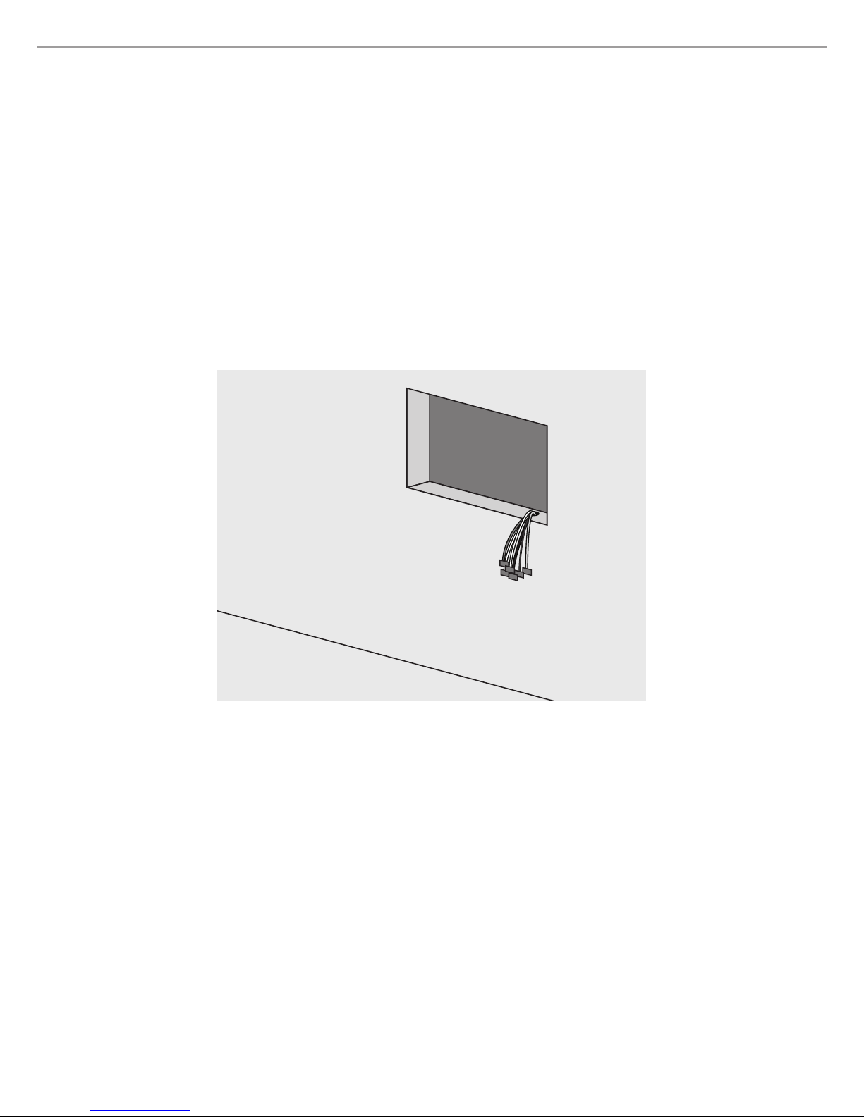
It is advisable that all the necessary cables to the TV , even those that are not needed
at the moment but may be used in the future, are available and suitably prepared and
fixed to the TV beforehand since there is no easy method of accessing the TV back after
it has been installed.
Make sure that the cavity cutout space, including an aperture where cables are led
through, is dry and well isolated from any source of humidity e.g. condensation, damp,
running water, etc.
The area of the wall overlapped by bathovision’s mirror should be well prepared to
remove any loose material, thoroughly cleaned and dried making sure that there is no
loose paint, wallpaper or any layer of material that could easily detach from the wall.
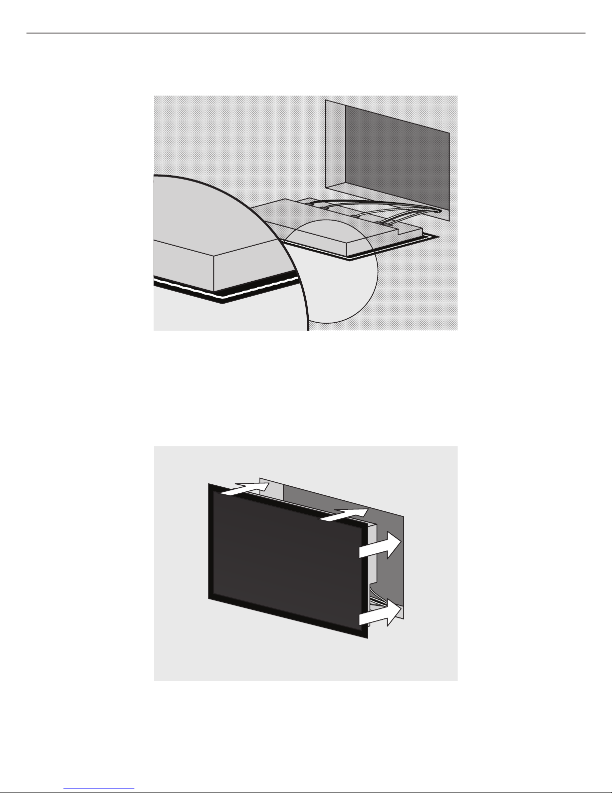
Prepare the mounting3.
The method of retaining the TV in the cavity cutout will depend entirely on the type of
wall into which the TV is being installed, e.g. brick, concrete, plasterboard, steel, wood,
etc. The installer should ensure that the bathovision™ is safely and securely retained in
the cavity by following industry recommended best practice for fixing such devices, as
applicable to the specific installation. Due consideration must be given to the prepared
dimensions of the wall cavity. Do not exceed the dimensions shown.
ATTENTION: The installer must take special care to ensure that the TV has been
safely and securely mounted within the cavity space and poses no risk for the user.
Unique Automation cannot take responsibility for any damage or injury caused through
improper installation of the product or due to the poor condition of the wall material.
Connect the cables and perform tests4.
Connect all the cables to the back of the TV. Make sure that they are all securely
fixed and that the mounting process will not exert any tension on them or that they can
be accidently pulled out of their connections during the sealing process. Power the TV
on and test all possible input and output connections before sealing the unit to the wall.
Check the operation of the hand controller and the touch screen controls to the front right

bathovision - installation manual
page 4
of the mirror. Check the audio output to speakers. When satisfied that all connections
have been made and secured and that the TV is operating correctly, the silicon sealant
is ready to be applied to the rear of the mirror. At this point switch off the television and
switch off the mains electricity supply to the television.
Figure 2.
Seal5.
It is recommended that a support for the mirror television is provided to enable ease
of working. A bead of the special silicon sealant provided should be applied continuously
around the rear surface of the mirror and close to the edge of the mirror. Use in accord-
ance with the instructions on the sealant. It is important to provide sufficient silicon seal-
ant to ensure a complete and continuous seal between the wall (or tiles) and rear of the
mirror. The silicon sealant must fully protect the body of the television mounted on the
rear of the mirror from water, steam or humidity of any kind.

bathovision - installation manual
page 5
Figure 3.
Slide the TV into the cavity6.
Figure 4.
If the TV is being mounted centrally in the wall cavity cutout the installer should pro-

bathovision - installation manual
page 6
vide a suitable spacer to raise the base of the TV such that it is centralised in the cavity
cutout. Carefully present the TV to the cavity cutout and gently slide the TV into the re-
cess. Make sure that all the cables are clear and free of the sides and top and base of the
cutout. Push the TV home against the wall or tiles making sure that the sealant on the rear
of the mirror is pressing against the wall and that a waterproof seal is achieved all round
the rear of the mirror. Remove or smooth out any excess sealant around the edges of the
mirror as soon as practical. Any minor gaps remaining may be filled with the sealant. A
degree of limited pressure should be exerted on the front of the TV mirror whilst the seal-
ant sets into position. The special silicon sealant supplied will retain a degree of flexibility
when fully set. Maximum adhesion will be achieved after approx. 24 hours. Should you
wish to remove the TV from the wall after the silicon sealant has set please contact the
company for advice. Once sealed, never attempt to prise the TV off the wall.
Verify the connections7.
Switch on the mains electricity supply to the television and switch on the television.
Test that the held controller is working correctly and that the touch screen controls are
operating correctly. The bathovision™ is ready for the program set up procedure. (For
the program set up procedure - see the bathovision™ operating manual).
Figure 5.

bathovision - installation manual
page 7
TV dimensions
bathovision
TV model
mirror
width
mirror
height
back box
width
back box
height
back box
depth
active
screen
width
active
screen
height
product ref.
23" 610 410 550 350 allow 75 509 286 LD-23B6LVH
26" 690 470 632 406 allow 75 576 324 LD-26S6LVH-2H
32" 830 540 769 483 allow 85 698 392 LD-32S6LVH-2H
40" 1020 640 957 583 allow 90 885 498 LD-40Q6LVH-2H
46" 1150 720 1088 661 allow 100 1018 573 LD-46Q6LVH-2H
bathovision TV sizesTable 2. (in mm)
As a result of our policy of continuous improvement, specifications and instructions
may change without notice.

bathovision - installation manual
page 8
12 – 14 Orion Business Centre
Surrey Canal Road
London
SE14 5RT
T: +44 (0) 20 7740 3910
F: +44 (0) 20 7232 0972
www.bathovision.tv
Table of contents