Universal Analyzers 500 series User manual

MAN.500.REVD.06302015
Instruction Manual
500 Series
Thermoelectric Gas Coolers
(Units sold prior to 07-01-2015)
5200 Convair Drive Carson City, NV 89706 • Phone: 775-883-2500 • Fax: 775-883-6388 • www.universalanalyzers.com

Page 2 of 44 Page 3 of 44
MAN.500.REVD.06302015
Contents
Receiving and Storage 4
Denition of Symbols 5
Specications 6
Description and Principle of Operation 8
Installation 11
Electrical Connections 12
Start-Up 18
Shutdown 18
Maintenance 19
Troubleshooting 20
Spare Parts 22
Drawings 23
Model 520 23
Model 530 24
Model 540 25
Model 560 26
Model 565 27
Model 570 28
Model 574 29

Page 2 of 44 Page 3 of 44 MAN.500.REVD.06302015
Contents
Drawings - Controller Boards 30
Display Boards for Models 520, 530, 560, 565 30
Display Board for Models 540, 570, 574 31
Relay Board for Models 520, 530, 560, 565 32
Relay Board for Models 540, 570, 574 33
Drawings - Heat Exchangers 34
Metallic Heat Exchangers (Temperature Sensing) All Models 34
Metallic Heat Exchangers (Non-Temperature Sensing) All Models 36
Glass Kynar (Temperature Sensing) All Models 38
Glass Kynar (Non-Temperature Sensing) All Models 40
Limited Warranty 42

Page 4 of 44 Page 5 of 44
MAN.500.REVD.06302015
Receiving and Storage
The Universal Analyzers 500 Series Thermoelectric Gas Coolers are complete pre-installed units. No assembly is
necessary when received on-site.
Carefully inspect the product and included accessories immediately on arrival by removing them from the packing and
checking for missing articles against the packing list.
Check the items for any damage which may have occurred during transit and immediately inform the shipping insurance
company of any damage found.
Refer to the Specications section (page 6) for information regarding storage requirements.

Page 4 of 44 Page 5 of 44 MAN.500.REVD.06302015
Denition of Symbols
WARNING - EXPLOSION HAZARD - DO NOT DISCONNECT EQUIPMENT UNLESS POWER HAS BEEN SWITCHED
OFF OR THE AREA IS KNOWN TO BE NON-HAZARDOUS.
WARNING - EXPLOSION HAZARD - SUBSTITUTION OF COMPONENTS MAY IMPAIR SUITABILITY FOR
HAZARDOUS AREA INSTALLATION.
THE SUPPLY POWER CIRCUIT MUST INCLUDE AN OVERPROTECTION DEVICE WITH A MAXIMUM RATING OF 20
A. A DISCONNECT SWITCH MUST BE LOCATED IN CLOSE PROXIMITY TO THE PROBE.
IF THE EQUIPMENT IS USED IN A MANNER NOT SPECIFIED BY THE MANUFACTURER, THE PROTECTION
PROVIDED BY THE EQUIPMENT MAY BE IMPAIRED PER CLAUSE 5.4.4(i) IN STANDARD EN 61010-1
CAUTION, RISK OF DANGER SYMBOL INDICATES INJURY MAY OCCUR IF MANUFACTURER’S INSTRUCTIONS
ARE NOT ADHERED TO. PLEASE READ MANUAL CAREFULLY WHEN SYMBOL IS DISPLAYED
CAUTION, HOT SURFACE SYMBOL INDICATES EXPOSED SURFACE TEMPERATURE CAN CAUSE BURNS OR
PERSONAL INJURY. CARE SHOULD BE TAKEN WHEN CONTACT IS REQUIRED.
CAUTION, RISK OF ELECTRICAL SHOCK SYMBOL INDICATES ELECTRICAL SHOCK MAY OCCUR. CAUTION
SHOULD BE TAKEN BEFORE DISCONNECTING OR CONTACTING ANY ELECTRICAL CONNECTIONS.
PROTECTIVE CONDUCTOR TERMINAL SYMBOL INDICATES THE TERMINAL LOCATION FOR THE
PROTECTIVE CONDUCTOR. FAILURE TO CONNECT TO THE PROTECTIVE CONDUCTOR TERMINAL MAY RESULT
IN A SHOCK HAZARD.

Page 6 of 44 Page 7 of 44
MAN.500.REVD.06302015
Specications
OPERATING SPECIFICATIONS
Sample Flow Rate
Model 520 0 to 2 1/2 l/m total (at STP)
Model 530 0 to 5 l/m total (at STP)
Model 540 0 to 4 l/m total (at STP)
Model 560 0 to 5 l/m total (at STP)
Model 570 0 to 4 l/m total (at STP)
Model 574 0 to 4 l/m total (at STP)
Maximum Inlet Temperature
Stainless Steel Heat Exchanger 700°F (351°C)
Kynar/Glass Heat Exchanger 280°F (138°C)
Maximum Inlet Gas Dew Point 180°F (82°C)*
Maximum Inlet Water Concentration 50%*
Minimum Ambient Temperature 34°F (1°C)
Maximum Ambient Temperature 105°F (41°C)*
Maximum Cooling Power
Model 520 63 BTUs per hour (60 kJ/hr)
Model 530 63 BTUs per hour (60 kJ/hr)
Model 540 126 BTUs per hour (120 kJ/hr)
Model 560 126 BTUs per hour (120 kJ/hr)
Model 570 126 BTUs per hour (120 kJ/hr)
Model 574 126 BTUs per hour (120 kJ/hr)
Outlet Sample Dew Point 41°F (5°C)
Gas Sample Inlet Fitting 3/8" tubing tting
Gas Sample Outlet Fitting 1/4" tubing tting
Bottom Water Drain Fitting 3/8" tubing tting
Maximum Input Power
Model 520 250 watts
Model 530 250 watts
Model 540 475 watts
Model 560 475 watts
Model 570 475 watts
Model 574 925 watts
Voltage
All models 90-132/180-264VAC, 50/60 Hz
Electrical Classication General Purpose, NEMA 1
Dimensions **
Model 520 11" H x 9" W x 9" D
Model 530 11" H x 11" W x 9" D
Model 540 11" H x 11" W x 10" D
Model 560 11" H x 9" W x 9" D

Page 6 of 44 Page 7 of 44 MAN.500.REVD.06302015
Model 570 11" H x 11" W x 10" D
Model 574 11" H x 11" W x 11" D
Weight
Model 520 19 lbs (8.5 kg)
Model 530 21 lbs (9.5 kg)
Model 540 21 lbs (9.5 kg)
Model 560 21 lbs (9.5 kg)
Model 570 25 lbs (11.5 kg)
Model 574 25 lbs (11.5 kg)
Soluble Gas Removal Rates NO 0% loss
NO2<10% loss
SO2< 2% loss
CO 0% loss
CO2< 2% loss
Storage Requirements Cool and dry location, -20°F < x < 120°F
< 95° relative humidity, non-condensing
* AT REDUCED FLOW RATE ABOVE 77°F (25°C) AMBIENT
** DIMENSIONS DO NOT INCLUDE FITTINGS OR MOUNTING HARDWARE
Specications

Page 8 of 44 Page 9 of 44
MAN.500.REVD.06302015
Description and Principle of Operation
APPLICATION
In order to accurately analyze combustion gases, moisture must be removed from the sample without removing gas
components of interest. The Universal Analyzers Thermoelectric Gas Cooler provides an ideal repeatable, and stable way
to decrease the dew point of combustion gasses. This prevents water condensation in sample prelters, sample pumps,
and gas analyzers. Where water vapor is an interferrent, a stable and repeatable dew point becomes a part of the gas
analyzer’s performance specication. The 500 Series Cooler provides this constant, resulting in an accurate analysis of
the gas components of interest.
The gas sample is rst pulled through a sample probe, which usually contains a heated lter, and then through a heated
sample line, which keeps the sample above its dew point. The 500 Series Cooler then condenses water out of the sample,
which lowers the dew point to 5°C (41°F).
The 500 Series Thermoelectric Gas Coolers are for general purpose, light duty applications. Several models are available
to meet various application conditions. Use the cooler selection chart below to best t a model to the expected ow rates,
water vapor concentrations, and ambient temperature conditions. If none of the models listed meet the needs of the
application, contact your Universal Analyzers local sales representative for more options.
GAS COOLER SELECTION CHART
Conditions Model
Ambient Water 520 530 540* 560 570 574* 574*
77°F
(25°C)
12% 2.5 l/m 4.0 l/m 2.5 l/m 5.0 l/m 4.0 l/m 5.0 l/m 2.5 l/m
15% 2.0 l/m 4.0 l/m 2.0 l/m 4.0 l/m 4.0 l/m 4.0 l/m 2.0 l/m
30% 1.0 l/m 4.0 l/m 1.0 l/m 2.0 l/m 4.0 l/m 2.0 l/m 1.0 l/m
50% 0.6 l/m 4.0 l/m 0.6 l/m 1.0 l/m 4.0 l/m 1.0 l/m 0.6 l/m
90°F
(32°C)
12% 2.0 l/m 3.0 l/m 2.0 l/m 4.0 l/m 3.0 l/m 4.0 l/m 2.0 l/m
15% 1.8 l/m 3.0 l/m 1.8 l/m 3.5 l/m 3.0 l/m 3.5 l/m 1.8 l/m
30% 0.9 l/m 3.0 l/m 0.9 l/m 1.8 l/m 3.0 l/m 1.8 l/m 0.9 l/m
50% 0.5 l/m 3.0 l/m 0.5 l/m 0.9 l/m 3.0 l/m 0.9 l/m 0.5 l/m
105°F
(41°C)
12% 1.5 l/m 2.0 l/m 1.5 l/m 3.0 l/m 2.0 l/m 3.0 l/m 1.5 l/m
15% 1.2 l/m 2.0 l/m 1.2 l/m 2.5 l/m 2.0 l/m 2.5 l/m 1.2 l/m
30% 0.6 l/m 2.0 l/m 0.6 l/m 1.3 l/m 2.0 l/m 1.3 l/m 0.6 l/m
50% 0.3 l/m 2.0 l/m 0.3 l/m 0.7 l/m 2.0 l/m 0.7 l/m 0.3 l/m
# of Gas Streams 1121224
*THE DATA PROVIDED IS FOR EACH STREAM
Various combustion processes can produce high levels of corrosive elements. An array of materials is available for the
500 Series Coolers, where gases come into contact with heat exchangers. 316SS is the most common option, and meets
the needs of most general purpose applications. Coatings of Silconert™ 2000, or Teon® may be added to the stainless
steel heat exchanger to enhance chemical resistance. Heat exchangers may also be made of other materials for corrosion
resistance, such as Glass/Kynar®, Kynar®/Kynar®, and Hastelloy®C276. Contact your local sales representative for
information on which material is best suited for your application.
New Jersey Thermocouple Types K and J are available for external monitoring of heat exchanger temperatures.

Page 8 of 44 Page 9 of 44 MAN.500.REVD.06302015
Description and Principle of Operation
DESCRIPTION
The Universal Analyzers 500 Series Thermoelectric Gas Coolers condition gas sample streams to remove water vapor. The
gas sample is cooled thermoelectrically to a controlled temperature, and water vapor is condensed and removed.
The key to success is being able to condense the water from a wet gas sample with a minimal loss of the water soluble gas
fraction. The separation occurs in a classical impinger, which has a highly polished cylindrical surface, cooled to the desired
dew point temperature. The gas sample is brought to the bottom of the cylinder through an insulated tube and allowed to
rise through a narrow annular area at a relatively high Reynolds number to insure the entire sample is inuenced by the cold
surface. The condensate falls down the cold, polished surface in the form of a sheet (as opposed to droplets or the bubbling
of the gas sample through the condensate) which minimizes the surface area in contact with the gas sample.
The temperature of the cylindrical, condensation surface of the heat exchangers is maintained through intimate contact with
aluminum heat transfer blocks. The blocks are cooled with thermoelectric elements, controlled to a temperature of 5°C. The
temperature sensor is a type “K” thermocouple. The temperature controller is proportional with a band of 1°C.
The fan cooled heat sink is constructed from anodized, pure aluminum ns which transfer heat to the surrounding air. The
pure aluminum material is a far better conductor of heat than the aluminum alloys which are normally used for extruded heat
sinks. The result is an assembly with superior heat exhausting capabilities under high ambient temperature conditions.
The 500 Series Coolers have a digital display for front panel indication of the operating temperature of each of the heat
transfer blocks (switch selectable) in degrees Centigrade. Two internal jumpers at the top of the control circuit board within
the enclosure can be moved to change the indicated temperature to read out in degrees Fahrenheit.
Three LED lamps to indicate the status of the cooler. The “COOL” lamp is a green LED which indicates when the operating
temperature has fallen below the factory set temperature of 10°C. An “Over-temperature relay” is energized and closed to
the cool position when the “COOL” lamp is on. The relay board within the enclosure has dual terminal strip relay contacts for
alarm/shutdown purposes. The external gas sample pump may be interlocked with this relay to power off when temperatures
become too high (fail safe).
The “DRY” lamp is a green LED which indicates when there is no water in contact with the water carry-over sensor (provided
separately or as a system option). If no moisture sensor is used, the lamp may be turned off by installing a jumper on the
moisture sensor input terminals on the relay board. Without a moisture sensor installed, the “DRY” lamp is always lit and
doe not indicate a condition. The moisture sensor relay, which is energized in the “DRY” condition, provides contacts to an
annunciator panel and/or to turn off the sample pump in the “wet” condition.
The “TC” lamp is a red LED which indicates when there is a problem (open connection) in the temperature control
thermocouple. The “Over-temperature” relay will also transfer to the high temperature condition if the red “TC” lamp
comes on.
The WCO or WCOF, optionally available with the 500 Series Cooler Systems, is a sensor which detects the presence of
liquid water. One should be placed in each gas sample stream directly after the cooler to provide an alarm if condensate is
detected. The electronics associated with water carry-over sensors are included as a standard part of all Universal Analyzers
Thermoelectric Sample Coolers. Dual relay contact sets are provided for each moisture sensor. Relay contacts are energized
and closed to the dry position when the WCO sensor is dry and the unit is powered on.
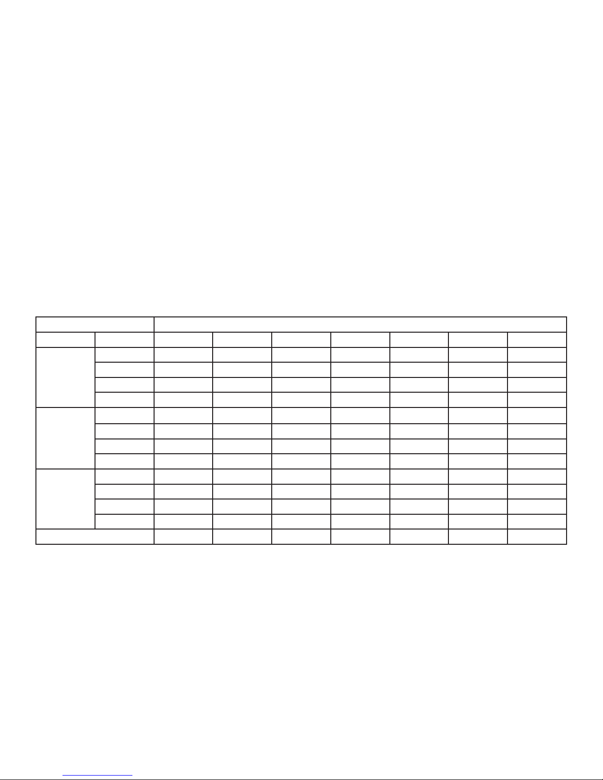
LED INDICATOR CHART
LED Color Status Condition Relay Status
COOL Green On Operating properly, temperature below 10°C Over Temperature: Energized, towards COLD
Off Temperature too high or unit is OFF Over Temperature: De-Energized, towards HOT
DRY Green On WCO sensor connected and sample is dry Moisture Sensor: Energized, towards DRY
Off Moisture detected or jumper installed Moisture Sensor: De-Energized, towards WET
TC Red On Temperature control TC has BAD quality Over temperature: De-Energized, towards HOT
Off Temperature control TC has OK quality Does not affect relays

Page 10 of 44 Page 11 of 44
MAN.500.REVD.06302015
DESCRIPTION
A gas sample pump may be provided as part of the sampling system. If the pump is placed ahead of the sample cooler, it
should be provided with a heated head to avoid the condensation of water vapor. If the sample pump is placed after the
sample cooler, drawing the sample through the cooler, the sample has been dried, and a standard, non-heated pump may
be used.
A means to control the ow of the sample through the system should be available and visible to the operator. This may be
accomplished through the use of pressure regulators with gauges, owmeters, and/or ow control needle valves.
Condensate removal from the heat exchanger(s) within the Sample Cooler can be accomplished through one of the
following methods:
1. A continuously running peristaltic tubing pump.
2. Installing the heat exchanger as a bypass condenser, pulling excess sample through with an eductor.
3. Using oat drain traps similar to a steam trap. This requires the sample within the cooler to be at a positive pressure.
4. Use of drain pots on level control with a removal pump.
Description and Principle of Operation

Page 10 of 44 Page 11 of 44 MAN.500.REVD.06302015
Installation
The 500 Series Thermoelectric Gas Coolers are best suited for air conditioned environments. Each unit dissipates
heat, and the surrounding area must be well ventilated to provide adequate cooling. The cooler should be located away
from other heat sources. If located inside an enclosure, outside air should be ducted directly onto the heat sink, and
thermostatically controlled fans and vents should be utilized. The interior of the enclosure should be insulated, and never
mount the unit in direct sunlight to avoid solar heat loading.
Route all sample gas lines directly to the 3/8” inlet tubing ttings located on the top of the cooler heat exchangers. When
two gas streams are being cooled, the left side of the unit is considered to be channel 1, and the right side of the unit is
channel 2. Sample outlet tubing ttings are reduced to 1/4".
At the bottom of each heat exchanger, a 3/8” tubing tting is provided for the condensate drain. The condensate tting
may be removed to expose a female 3/8” NPT connection. Equipment must be installed to remove the condensate such
as a peristaltic pump, liquid drainer, or aspirated drainer. A single head peristaltic pump is recommended. If an aspirator
drain is utilized, the outlet tubing should have a small bore and be no longer than two feet to minimize back pressure. The
drain must be run to an appropriate condensate disposal location.
A sample pump is normally required to pull the gas sample through the cooler. A Water Carry-Over Filter (WCOF) sensor
is recommended for each sample path. The pump should be located between the cooler and the lter. A clear glass bowl
should be installed around the lter to allow checking of the condition of the lter while online.
Each cooler consumes about 2 amps (at 115VAC) per every active heat exchanger. Use minimum wire size of 18 AWG,
stranded, tinned copper with a minimum rating of 300 Volts. Dual relays are provided for both the WET/ DRY and HOT/
COLD conditions. One set of relays are MOV protected and designed to interrupt power to the sample pump upon alarm.
The temperature of the heat exchangers may be viewed on the display on the front of the unit. If a multiple channel unit
has been provided, a selector switch on the right side of the display lets the user toggle the display from one block to the
other. For these same cooler models, a second toggle switch on the left side of the display allows the user to view the
settings for the relay and cooler temperatures. Jumpers inside the unit on the control panel allow setting the display for
degrees Celsius or degrees Fahrenheit.
Sample pumps, WCOF sensors, drains, ow meters, regulators, and other optional equipment are available from
Universal Analyzers. These may be purchased separately or installed on a complete 500 Series Sample
Conditioning System.
All installations shall be in accord with the manufacturer’s instructions and the National Electric Code (ANSI/NFPA 70).

Page 12 of 44 Page 13 of 44
MAN.500.REVD.06302015
Electrical Connections Model 520

Page 12 of 44 Page 13 of 44 MAN.500.REVD.06302015
Electrical Connections Model 530

Page 14 of 44 Page 15 of 44
MAN.500.REVD.06302015
Electrical Connections Model 540

Page 14 of 44 Page 15 of 44 MAN.500.REVD.06302015
Electrical Connections Model 560

Page 16 of 44 Page 17 of 44
MAN.500.REVD.06302015
Electrical Connections Model 570

Page 16 of 44 Page 17 of 44 MAN.500.REVD.06302015
Electrical Connections Model 574

Page 18 of 44 Page 19 of 44
MAN.500.REVD.06302015
Start-Up
Apply power to the Universal Analyzers 500 Series Thermoelectric Gas Cooler. The indicated temperature will start to
drop immediately. It should be below the over-temperature set point in approximately four minutes and the “COOL” green
LED lamp should light. When the temperature reaches the control point (set at 5°C), the rate at which the temperature
drops will be reduced. It will stabilize between 4°and 5°C.
Start the sample gas ow. Water should be observed to be removed from the bottom of the heat exchanger when steady
state conditions are established.
If moisture sensors are installed, the (DRY) light should remain on as dry gas is transported to the analyzer(s). Turn on the
analyzer(s) and calibrate as required.
Shutdown
Stop sample gas ow to the Universal Analyzers 500 Series Thermoelectric Gas Cooler by turning off the sample pump.
Allow the drain pump to run for several minutes to remove any remaining condensate from the heat exchangers. After all
condensate has been drained, turn off power to the cooler.

Page 18 of 44 Page 19 of 44 MAN.500.REVD.06302015
Maintenance
Before performing any maintenance on the 500 Series Thermoelectric Gas Cooler, ensure that all plant safety
procedures are followed.
The 500 Series Cooler is designed for maintenance free operation, but if any is required, ensure power has been removed
before maintenance is performed.
For the best performance of the cooler, the following maintenance schedule is recommended:
Maintenance Activity Frequency
Peristaltic pump Replace tubing every 3 months
Diaphragm sample pump Replace diaphragm every 6 months
Clean heat exchanger Annually
Inspect heat sink ns Monthly

Page 20 of 44 Page 21 of 44
MAN.500.REVD.06302015
Troubleshooting
The following table should give an overview of possible errors and an instruction to check and to repair them (is not valid
for the starting-up period of cooler).
Error Possible reason Check/Repair
The presence of water Overloading of the refrigeration
capacity of the cooler due to too
much water vapor or too great a
sample ow rate
A fault in the condensate removal
equipment. The heat exchanger has
become full of condensate
An air leak in the condensate
removal tubing
The pressure of the compressed air
driving the vortex tube has dropped
below 60 psig at the inlet of the
thermal valve
Failure of the sample cooler
The cooler is not cold enough
and needs to be calibrated. See
calibration procedure below
No sample gas ow Heat exchanger plugged
Alarm shutoff
No power on cooler
Check for an obstruction
Remove heat exchanger from unit and
disassemble
Verify Cool & Dry Indicators are illuminated
Ensure cooler has power supplied
Water carry over Inadequate drain apparatus
Excessive ow rate
High ambient temperature
Defective cooler
Verify drain tubing is unobstructed and
equipment is functioning satisfactory
Reduce the ow rate
Reduce the ambient temperature (Increase
ventilation or relocate cooler)
Verify air ow across the heat sink
Hold hand in front of heat sink ns and ensure
air movement
This manual suits for next models
7
Table of contents
Popular Freezer manuals by other brands

Electrolux
Electrolux EU 1420 T Installation and instruction manual

Elba
Elba ELBA-272 User instruction

Follett
Follett FZR8-PC Installation and operation manual

Jägermeister
Jägermeister Speed Pour Freezer owner's manual

Electrolux
Electrolux EJF4340ALW user manual

Frigidaire
Frigidaire FFFU21M1QWA use & care