US Blaster USB 71 00 User manual

2Copyright U.S. Blaster Europe BV © - Delft - Netherlands
ENG
Copyright U.S. Blaster Europe BV - Delft - Netherlands
CAUTON
Cautions
1.All operating instructions should be read
before using this equipment.
2. To reduce the rise of electrical shock, do
not open the unit. There are No USER
REPLACEABLE PARTS INSIDE.
3. Do not expose this unit to direct sunlight
or to a heat source.
4. This unit should be cleaned only with a
damp cloth. Avoid solvents or Othe cle-
aningdetergents.
5. When moving this equipment, it should
be placed in its original Carton and pac-
kaging. This will reduce the risk of
damage during Transit.
6. DO NOT EXPOSE THIS UNIT TO RAIN OR
MOISTURE.
7. DO NOT USE ANY SPRAY CLEANER OR
LUBRICANT ON ANY CONTROLS OR
SWITCHES.
U.S. Blaster Europe b.v. asumes no
responsibility for any damage that could
occur due to improper connection of this
product.
Achtung
1. Lesen Sie die gesamte
Bedienungsanleitung durch, bevor Sie
dieses Gerät verwenden.
2. Um die Gefahr von Stromschlägen zu
vermeiden, sollten Sie das Gerät nicht
öffnen. Es gibt keine VOM BENUTZER
AUSTAUSCHBAREN TEILE IM INNEREN.
3. Setzen Sie dieses Gerät nicht direktem
Sonnenlicht.
.4.Dieses Gerät sollte nur mit einem
feuchten Tuch gereinigt werden.
Vermeiden Sie Lösungsmittel oder
andere Reinigungsmittel.
5. Wenn Sie das Gerät an einen anderen
Ort bringen, sollten Sie es mit der
Originalverpackung in den
Originalkarton verpacken. Dies reduziert
die Gefahr von Beschädigungen
während des Transports.
6. SETZEN SIE DIESES GERÄT NICHT
REGEN ODER FEUCHTIGKEIT AUS.
7. VERWENDEN SIE KEINE
SPRÜHREINIGER ODER SCHMIERMIT-
TEL AN BEDIENLEMENTEN ODER
SCHALTERN.
U.S. Blaster Europe b.v. übernimmt keine
Verantwortung für Schäden, die durch
nicht ordnungsgemäßes Anschließen des
Produkts verursacht werden.
Avertissements
1. Toutes les instructions de fonction-
nement doivent être lues avant d’utilis-
er l’équipement.
2. Afin de réduire les risques de décharge
électrique, n’ouvrez pas l’unité. Il n’ex-
iste PAS de PIECES REMPLACABLES
PAR L’UTILISATEUR A L’INTERIEUR.
3. N’exposez pas cette unité aux rayons
directs du soleil.
4.Cette unité doit être nettoyée unique-
ment avec un chiffon humidifié. Evitez
les solvants ou les produits détergents.
5. Lorsque vous transportez cet
équipement, il doit être placé dans son
carton et son emballage d’origine. Ceci
réduira
les risques d’endommagement durant le
transport.
6. N’EXPOSEZ PAS CETTE UNITE A LA
PLUIE OU A L’HUMIDITE.
7. N’UTILISEZ PAS DE NETTOYANT EN
VAPORISATEUR NI DE LUBRIFIANT SUR
LES COMMANDES OU LES BOUTONS.
U.S. Blaster Europe b.v. décline toute
responsabilité concernant tout dommage
pouvant résulter d’un branchement incor-
rect de ce produit.
Waarschuwingen
1. Vóór het gebruik van deze apparatuur
dient u alle bedieningsinstructies te heb-
ben doorgenomen.
2. Open de eenheid niet, om elektrische
schokken te voorkomen. IN DE APPARA-
TUUR BEVINDEN ZICH GEEN ONDERDE-
LEN DIE DOOR DE GEBRUIKER KUNNEN
WORDEN VERVANGEN.
3. Stel deze eenheid niet bloot aan direct
zonlicht of hittebronnen.
4. Deze eenheid mag alleen worden gerei-
nigd met een vochtig doekje. Gebruik
geen oplos- of andere reinigingsmidde-
len.
5. Bij het verplaatsen van deze apparatuur
dient u deze in de originele kartonnen
verpakking te plaatsen. Hiermee
voorkomt u schade tijdens het transport.
6. STEL DEZE EENHEID NIET BLOOT AAN
REGEN OF VOCHT.
7. GEBRUIK GEEN REINIGINGSSPRAYS OF
SMEERMIDDELEN VOOR DE REGE-
LAARS OF SCHAKELAARS.
U.S. Blaster Europe b.v. is niet verantwoor-
delijk voor enige schade die voortvloeit uit
een onjuiste aansluiting van dit product.
Precauzioni
1. Si devono leggere tutte le istruzioni
operative prima di utilizzare questo
impianto.
2. Al fine di ridurre il rischio di scosse
elettriche, non aprire l'apparecchio.
ALL’INTERNO NON VI SONO PARTI CHE
POSSONO ESSERE SOSTITUITE DALL’U-
TENTE.
3. Non esporre questa unità alla luce
diretta del sole.
4. Questa unità dev’essere pulita unica-
mente mediante un panno inumidito.
Evitare solventi o altri detergenti di puli-
tura.
5. Per il trasporto di questo apparecchio si
raccomanda di riporlo nel suo scatolone
e imballaggio originale. Questo fatto
ridurrà il rischio di danni durante il
trasporto.
6. NON ESPORRE QUESTO APPARECCHIO
ALLA PIOGGIA O ALL'UMIDITÀ.
7. NON IMPIEGARE ALCUN PULITORE
NEBULIZZANTE O
LUBRIFICANTE SU NESSUN COMANDO O
INTERRUTTORE.
La U.S. Blaster Europe b.v. non si assume
alcuna responsabilità per qualsiasi even-
tuale danno che potesse succedere a
causa di un inappropriato collegamento di
questo prodotto.
Cautions
1.All operating instructions should be read
before using this equipment.
2. To reduce the rise of electrical shock, do
not open the unit. There are No USER
REPLACEABLE PARTS INSIDE.
3. Do not expose this unit to direct sunlight
or to a heat source.
4. This unit should be cleaned only with a
damp cloth. Avoid solvents or Othe cle-
aningdetergents.
5. When moving this equipment, it should
be placed in its original Carton and pac-
kaging. This will reduce the risk of
damage during Transit.
6. DO NOT EXPOSE THIS UNIT TO RAIN OR
MOISTURE.
7. DO NOT USE ANY SPRAY CLEANER OR
LUBRICANT ON ANY CONTROLS OR
SWITCHES.
U.S. Blaster Europe b.v. asumes no
responsibility for any damage that could
occur due to improper connection of this
product.
THIS PRODUCTS ARE NOT INCLUDED!
ALSO AVAILABLE FROM:WWW.USBLASTER.COM

3
Copyright U.S. Blaster Europe BV © - Delft - Netherlands
ENG
Copyright U.S. Blaster Europe BV - Delft - Netherlands
USB 5476
USB 5473
USB 7100
PROFESSIONAL
MIXER

INSTRUCTION MANUAL - PROFESSIONAL MIXER - USB 7100
Features:
*. 4 Stereo Channels
*. State of the Art Cue Section
*. 3 Phono/Line Convertible, 5 Line, and 2 Mic Inputs
*. 3 band (LOW MID HI) EQ for each channel
*. Talkover
*. Master, Booth and Record outputs
*. Digital Sampler with 5 Memory Banks
*. Battery backup to retain samples
Connections:
1. Before plugging in the power cord, make sure that the VOLTAGE SELECTOR (53) switch is set to the correct voltage.
NOTE: This product is double insulated and not intended To be grounded.
2. Make sure that the POWER (47) switch is the off position. The POWER LED (48) will be off.
3. The USB 7100 is supplied with 3 sets of amp output jacks. The MAIN OUTPUT (55) jacks are unbalanced and used to connect to your main amplifier. The REC OUTPUT
(56) jacks allow you to hook up an Additional amplifier.
4. The MIC 1(1) input (found on the front panel) accepts 1/4" or XLR connector. The MIC 2(69) input (found on the rear panel) accepts 1/4" connectors. ALL accept balan-
ced and unbalanced microphones. On the real panel are 3 stereo PHONO/LINE (62,65,68) inputs and 5 stereo LINE (58,59,60,63,66) inputs. The PHONO/LINES SWITCH
(62) enables you to set he (61) input to phono Line. The PHONO/LINE SWITCH (65) enables you to set the (65)input to Phono or Line.
The PHONO/LINE SWITCH (68) enables you to set the (67) input to phono or Line. The phono inputs will accept only turntables with a magnetic cartridge. A GROUND
SCREW(70)for you to ground your turntables is located on the rear panel. The Stereo Lin inputs will accept any line level input such as a CD player, et e.75. Headphones
can be plugged into the front panel mounted HEADPHONE (52) jack7 The USB 7100 comes with a front panel BNC LIGHT (46) jack. This jack is for use with a gooseneck
light.
Using the Ground Life Switch:
Depending on your system configuration, sometimes applying the Ground will create a quieter signal path. Sometimes lifting the ground Can eliminate ground loops and hum
to create a quieter signal path.
1. With the mixer on, listen to the system in idle mode (no signal present) with the ground applied (the GROUND LIFT SWITCH (70) in The left position)
2. Then turn the power off before moving the GROUND LIFT SWITCH (70). Lift the ground by moving the GROUND LIFT SWITCH to the right Turn the power back on and
listen to determine which position will provide a signal devoid of background noise and bum. Keep the GROUND LIFT SWITCH in the ground position if the noise level
remains the same in either position.
CAUTION: DO NOT TERMINATE THE AC GROUND ON THE POWER MIXER IN ANY WAY. TERMINATION OF THE AC GROUND CAN BE HAZARDOUS.
Operation:
1. POWER ON: Once you have made all the equipment connections to your mixer, press the POWER SWITCH (47). The power will turn on and the POWER LED (48) will
glow RED.
2. CHANNEL 1:Switch # (17) allows you to select the PHONO 1/LINE 1(67) or the LINE (2) 66 input. The GAIN (7) and CHANNEL SLIDE (12) controls the input level of this
channel. The EQ CUT (9,0,10) to allow you to adjust the sound.
3. CHANNEL 2:Switch # (17) allows you to select the PHONO 2/LINE 3 (64) or the LINE 4 (63) input. The GAIN (13) and CHANNEL SLIDE (18) controls the input level of
this channel. The EQ CUT (14,15,16) to allow you to adjust the sound.
4. CHANNEL 3:Switch # (23) allows you to select the PHONO 3/LINE 5(61) or the LINE 6 (60) input. The GAIN (19) and CHANNEL SLIDE (24) controls the input level of
this channel. The EQ CUT (20,21,22) to allow you to adjust the sound.
5. CHANNEL 4:Switch # (29) allows you to select the LINE 7 (59) or the LINE 8 (58) input. The GAIN (25) and CHANNEL SLIDE (30) controls the input level of this chan-
nel. The EQ CUT (26,27,28) to allow you to adjust the sound.
6. CROSSFADER SECTION: The CROSSFADER (32) allows the mixing of one source into another. The USB 7100 features an assignable crossfader. The ASSIGN (31,33) swit-
ches allow you to select Which channel will play through each side of the crossfader. The ASSIGN (31) switch has 5 settings (OFF,1,2,3.Or 4) and allows you to select
channel 1,2,3 or 4) and allows you to select channel 1,2,3,4 to play through the right side of the crossfader. With the ASSIGN switch in the off position. That side of the
crossfader will be inactive. The CROSSFADER (32) in your unit is removable and if need arises can be easily replaced.
7. OUTPUT CONTROL SECTION: The level of the MAIN OUTPUT (55) is controlled by the MASTERT (38) slide. Activating the MONO (37) button (the mono LED will light )
makes the overall output mono. The BOOTH (49) control adjusts the level of the BOOTH PUTPUT (56). HINT: The BOOTH OUTPUT is used by some Djs to run monitor spe-
akers in their Dj booth. You can also use it as a second ZONE or AMP output
NOTE: The REC OUTPUT (57) has no level control. The level is set by the channel gain or slides or the selected channel.
8. TALKOVER SECTION: The purpose of the talkover section is to allow the program playing to be muted so that the mic can be heard above the music. The MIC/TALKOVER
SWITCH (6) controls MIC 1 And MIC 2 and has three settings. When the MIC/TALKOVER SWITCH (6) is in the bottom position. MIC 1 and MIC 2 and talkover are off.
When the MIC/TALKOVER SWITCH (6) is in the center Position MIC 1 and MIC 2 are on, but talkover is off. When the MIC/TALKOVER SWITCH (6) is in the top position.
MIC 1 and MIC 2 and talkover will be on and the volume of all sources except the Mic input are lowered by 16 dB. The TREBLE (4) and BASS (5) controls allow you to
fully adjust the tone Of MIC 1 and MIC 2. MIC 1 LEVEL (1) controls the level of MIC 1. The MIC 2 LEVEL (2) controls the level of MIC 2.
9. CUE SECTION: By connecting a set of headphones to the HEADPHONE (52) jack, you can monitor any or of the channels, Press the CUE/SAMPLE ASSIGN (35) buttons
for channels 1-4 to Select the channel or channels to be monitored and their respective LED indicators will Red. Press the CUE/SAMPLE ASSIGN (34,35) buttons are also
used to adding samples (see sampler operation for more details). Press the CUE SAMPLER (39) to monitor samples. Use the CUE LEVEL (51) control to adjust the cue
volume without effecting the overall mix. By moving the CUE PGM PAM (50) control to the left you will be able to monitor the assigned cue signal. Moving the control to
the right will , monitor the PGM (program) output.
10. DISPLAY: The DISPLAY (36) indicates either the MASTER output left and right levels.
Sampler Operation:
1. GENERAL INFORMATION: The USB 7100 sampler uses Dynamic RAM Memory and a 16 bit microprocessor controller. The full bandwidth results in sound reproduction.
Results in true sound reproduction.
2. MWMORY INFORMATION: The USB 7100 comes equipped with five MEMORY BANKS (44). The two banks marked 2 &2 are two seconds in length, the two banks mar-
ked 4&4 are four seconds in length and the bank marked 12 is twelve seconds in length. These banks are separate and can not be linked. You can store a different sample
in each bank but they must be recorded individually and they must be played one at a time
SAMPLE RECORDING:
1. Put the MODE SELECTOR (43) switch into the WRITE position.
Select the source you want to sample from by pressing the appropriate CUE/SAMPLE ASSIGN (34,35) button. Select the memory bank you want to record into, by pressing
the proper MEMORY BANK (44) button.
2. The USB 7100 comes equipped with a sampler PITCH (41) control. To set a perfect sample, set the control to its center position and record the sample. During playback,
raising or lowering the control will raise or lower the pitch of the sample playback. The center position will remain as normal pitch
4Copyright U.S. Blaster Europe BV © - Delft - Netherlands
ENG

HINT: You can record sample with the PITCH (41) control in any position. Whatever that position is will become normal sound. If you start to record a sample with the
PITCH (41) control set at minimum (this now becomes your normal pitch), by increasing the pitch to maximum, the pitch effect will double in speed. Recording at maxi-
mum and lowering to minimum will do exactly the opposite.
3. Tapping the START/STOP (45) button begins the sampling process (the SAMPLER INDICATOR will illuminate RED). Tapping the SAMP; ER INDICATOR will turn off). If you
do not tap the START/STOP (45) button a second time, the sampling process will stop automatically after 2,4 or 12 seconds depending on which MEMORY BANK (44) was
selected.
SAMPLE PLAYBACK:
1. Put the MODE SELECETOR (43) switch into the SINGLE or REPEAT position.
2. Select the memory bank you wish to play by pressing the proper MEMORY BANK (44) button.
3. Tapping the STAR/STOP (45) button with the MODE SELECTOR (43) switch in the SINGLE position will cause the sampler to playback one time (the SAMPLER INDICTOR
will illuminate GREEN). Every push of the START/STOP (45) button will restart the sample from the beginning. Rapid pressing of the START/STOP button will cause a stut-
tering effect. Once the sample has started start playback and the START/STOP (45) button is not pushed a second time, the sample will play to the end and then stop (the
SAMPLER INDICATOR will turn off)
4. Tapping the START/STOP (45) button with the MODE SELECTOR (43) switch in the REPEAT position will cause the sample to continuously play over and over (the SAM-
PLER INDICATOR will illuminate GREEN). The START/STOP (45) button will act as an on/off switch. The first push will start the sample, the second push will stop it The
SAMPLER LEVEL (40) controls the level of the sample
ROBO PLAY:
With the ROBO PLAY (42) button in the OFF POSITION ( the ROBO PLAY INDICAOR will be OFF) and the MODE Selector (43) Switch in either the SINGLE or REPEAT mode.
Pressing the START STOP (45) button will cause the sample to play along with the selected source.
When the ROBO PLAY (42) button is in the ON position (the ROBO PLAY INDICAOR illuminator RED), starting the sampler mutes the selected source. When the sample
ends the source automatically turns back on.
BATTERY BACKUP: The USB 7100 is equipped with battery backup to retain samples. To activate this feature . a 9 volt battery (not included) needs to be connected to the
BATTERY HOLDER (54) located on the rear panel. this will enable you to store samples in memory, and when the unit is unplugged, the battery backup will retain the samp-
les for future use. If the unit is unplugged with no battery attached, all the sample will be lost
LOW BATTERY INDICATOR: A low battery indicator is included with the USB 7100. When changing the battery, make sure the unit is plugged in and the power is ON. Failure
to adhere to this will result in lost memory. The low battery indicator is ON when selected memory bank LED blinks. The LED will also blink if no battery is connected to the
unit.
5
Copyright U.S. Blaster Europe BV © - Delft - Netherlands
ENG
Specifications
INPUTS:
DJ Mic 1.5mV 2Kohm balanced
Phono 3mV 47Kohm
Line 150 mV 27Kohm
Aux 150 mV 27Kohm
OUTPUTS:
Main/Aux 0 dB 1V 400ohm
Max 20V Peak to Peak
Rec 225Mv 5Kohm
MIC 1&MIC 2:
DJ Mic 1.5mV 2Kohm balanced
Bass ±12dB
High ±12dB
GENERAL:
Frequency Response 20Hz-20KHz +/-2dB
Distortion 0.02%
S/N Ratio batter than 80dB
Talkover Attenuation 16dB
Headphone Impedance 16ohm
Powersource 115/230V 50/60Hz 10W
Dimensions 19"wx4"hx9"d
Weight 4,6 kg

7Copyright U.S. Blaster Europe BV © - Delft - Netherlands
D
INSTRUCTION MANUAL - PROFESSIONAL MIXER - USB 7100
Merkmale:
*. 4 Stereokanäle
*. Cue-Weg auf dem neuesten Stand der Technik
*. 3 umschaltbare Phono/Line-, 5 Line- und 2 Mikrophon-Eingänge
*. 3-Band-Equalizer (LOW, MID, HIGH) für jeden Kanal
*. Talkover
*. Master-, Booth- und Aufzeichnungsausgänge
*. Digitalsampler mit 5 Speicherbänken
*. Batterie-Backup für das Aufbewahren von Samples
Anschlüsse:
1. Achten Sie vor dem Anschließen des Netzkabels darauf, dass der SPANNUNGSWAHL-Schalter (53) auf die richtige Spannung eingestellt ist.
HINWEIS: Dieses Produkt ist doppelt isoliert und nicht dafür gedacht, geerdet zu werden.
2. Stellen Sie sicher, dass der NETZ-Schalter (47) auf Aus gestellt ist. Die NETZ-LED (48) ist ausgeschaltet.
3. Der USB 7100 wird mit 3 Sätzen Verstärkerausgangsbuchsen ausgestattet. Die MAIN-AUSGANGS-Buchsen (55) sind unsymmetrisch und werden für den Anschluss an Ihren
Hauptverstärker verwendet. Die REC-AUSGANGS-Buchsen (56) ermöglichen Ihnen den Anschluss eines zusätzlichen Verstärkers.
4. In den MIC 1-Eingang (1) (befindet sich an der Vorderseite) passt ein 1/4"- oder XLR-Stecker. In den MIC 2-Eingang (69) (befindet sich an der Rückseite) passt ein 1/4"-Stecker. ALLE sind
für symmetrische und unsymmetrische Mikrophone geeignet. An der Rückseite befinden sich 3 Stereo-PHONO/LINE- (62, 65, 68) und 2 Stereo-LINE- (58, 59, 60, 63, 66) Eingänge. Der
PHONO§/LINE-SCHALTER (62) ermöglicht es Ihnen, den Eingang (61) auf Phono oder Line einzustellen. Der PHONO/LINE-SCHALTER (65) ermöglicht es Ihnen, den Eingang (65) auf Phono
oder Line einzustellen.
Der PHONO/LINE-SCHALTER (68) ermöglicht es Ihnen, den Eingang (67) auf Phono oder Line einzustellen. Die Phonoeingänge sind nur für Abspielgeräte mit Magnetkassetten gedacht. Eine
ERDUNGSSCHRAUBE (70) für die Erdung Ihrer Abspielgeräte befindet sich an der Rückseite. Die Stereo/Line-Eingänge sind als Line-Pegel-Eingänge zum Beispiel für CD-Player, usw. gedacht.
5. Kopfhörer können an die KOPFHÖRER-Buchse (52) an der Vorderseite angeschlossen werden.
Das USB 7100 wird mit einer BNC-LICHT-Buchse (46) an der Vorderseite geliefert. Diese Buchse ist für die Verwendung mit einer Schwanenhalslampe gedacht.
Verwendung des Erdungsschalters:
Je nach Ihrer Systemkonfiguration schafft die Anwendung der Erdung einen ruhigeren Signalpfad. Manchmal kann durch die Aufhebung der Erdung Masseschleifen und Brummgeräusche elimi-
nieren und einen ruhigeren Signalpfad schaffen.
1. Hören Sie bei eingeschaltetem Mischpult dem System im Leerlauf (kein Signal vorhanden) mit angewandter Erdung zu (der ERDUNGSSCHALTER (70) befindet sich in der linken Position).
2. Schalten Sie dann den Netzschalter aus, bevor Sie den ERDUNGSSCHALTER (70) bewegen. Heben Sie die Erdung auf, indem Sie den ERDUNGSSCHALTER nach rechts bewegen. Schalten
Sie den Netzschalter wieder ein und hören Sie, um festzustellen, welche Position ein Signal ohne Hintergrundgeräusche und Brummen liefert. Lassen Sie den ERDUNGSSCHALTER in der
Erdungsposition, wenn der Geräuschpegel in allen Positionen derselbe bleibt.
ACHTUNG: SCHLIESSEN SIE DIE WECHSELSTROMERDUNG AM NETZMISCHGERÄT NICHT IN IRGENDEINER WEISE AB. DER ABSCHLUSS DER WECHSELSTROMERDUNG KANN
GEFÄHRLICH SEIN.
Bedienung:
1. NETZ EIN: Sobald Sie alle Geräte an Ihr Mischgerät angeschlossen haben, drücken Sie den NETZSCHALTER (47). Das Gerät schaltet sich ein und die NETZ-LED (48) leuchtet ROT.
2. KANAL 1: Der Schalter # (17) ermöglicht Ihnen die Auswahl des PHONO1/LINE 1- (67) oder LINE 2- (66) Eingangs. Die GAIN- (7)- und KANALSCHIEBEREGLER (12) steuern den
Eingangspegel dieses Kanals. EQ CUT (9, 0, 10) ermöglicht Ihnen das Einstellen des Sounds.
3. KANAL 2: Der Schalter # (17) ermöglicht Ihnen die Auswahl des PHONO 2/LINE 3- (64) oder LINE 4- (63) Eingangs. Die GAIN- (13)- und KANALSCHIEBEREGLER (18) steuern den
Eingangspegel dieses Kanals. EQ CUT (14, 15, 16) ermöglicht Ihnen das Einstellen des Sounds.
4. KANAL 3: Der Schalter # (23) ermöglicht Ihnen die Auswahl des PHONO 3/LINE 5- (61) oder LINE 6- (60) Eingangs. Die GAIN- (19)- und KANALSCHIEBEREGLER (24) steuern den
Eingangspegel dieses Kanals. EQ CUT (20, 21, 22) ermöglicht Ihnen das Einstellen des Sounds.
5. KANAL 4: Der Schalter # (29) ermöglicht Ihnen die Auswahl des LINE 7- (59) oder LINE 8- (58) Eingangs. Die GAIN- (25)- und KANALSCHIEBEREGLER (30) steuern den Eingangspegel
dieses Kanals. EQ CUT (26, 27, 28) ermöglicht Ihnen das Einstellen des Sounds.
6. CROSSFADER: Der CROSSFADER (32) ermöglicht Ihnen das Mischen von einer Quelle in eine andere. Der USB 7100 verfügt über einen zuweisbaren Crossfader. Die ASSIGN-Schalter (31,
33) ermöglichen Ihnen die Auswahl, welcher Kanal durch die jeweilige Seite des Crossfader wiedergegeben wird. Der ASSIGN-Schalter (31) hat 5 Einstellungen (Aus, 1, 2, 3 oder 4) und
ermöglich Ihnen die Auswahl von Kanal 1, 2, 3, oder 4 für die Wiedergabe an der rechten Seite des Crossfader. ASSIGN-Schalter in Position Aus. Diese Seite des Crossfader ist inaktiv. Der
CROSSFADER (32) in Ihrem Gerät kann entfernt und, falls nötig, problemlos ausgetauscht werden.
7. AUSGANGSSTEUERUNG: Der Pegel des MAIN-Ausgangs (55) wird durch den MASTER-Schieberegler (38) gesteuert. Durch Aktivieren der MONO-Taste (37) (die LED Mono leuchtet auf)
erfolgt die gesamte Ausgabe in Mono. Die BOOTH-Steuerung (49) stellt den Pegel des BOOTH-Ausgangs (56) ein. TIPP: Der BOOTH-AUSGANG wird von einigen DJs verwendet, um
Monitorlautsprecher in ihrem DJ-Booth laufen zu lassen. Sie können ihn auch als zweiten ZONEN- oder VERSTÄRKER-AUSGANG verwenden.
HINWEIS: Der REC-AUSGANG (57) hat keine Pegelsteuerung. Der Pegel wird durch die Kanalverstärkung oder Schieberegler des ausgewählten Kanals eingestellt.
8. TALKOVER: Talkover ermöglicht Ihnen die Stummschaltung des wiedergegebenen Programms, so dass das Mikrophon über der Musik zu hören ist. Der MIC/TALKOVER-SCHALTER (6) steu-
ert MIC 1 und MIC 2 und hat drei Einstellungen. Wenn der MIC/TALKOVER-SCHALTER (6) sich in der unteren Position befindet, sind MIC 1 und MIC2 und Talkover ausgeschaltet. Wenn der
MIC/TALKOVER-SCHALTER (6) in der mittleren Position ist, sind MIC 1 und MIC 2 ein- und Talkover ausgeschaltet. Wenn der MIC/TALKOVER-SCHALTER (6) sich in der oberen Position befin-
det, sind MIC 1 und MIC 2 und Talkover eingeschaltet und die Lautstärke aller Quellen mit Ausnahme des Mic-Eingangs wird um 16 dB verringert. Die TREBLE- (4) und BASS- (5)
Steuerungen ermöglichen Ihnen die vollständige Einstellung des Tons von MIC 1 und MIC 2. Der MIC 1 PEGEL (1) steuert den Pegel von MIC 1. Der MIC 2 PEGEL (2) steuert den Pegel von
MIC 2.
9. CUE-WEG: Wenn Sie Kopfhörer an die KOPFHÖRER-Buchse (52) anschließen, können Sie alle Kanäle überwachen. Drücken Sie die CUE/SAMPLE-ASSIGN-Tasten (35) für die Kanäle 1 –
4, um den oder die zu überwachenden Kanäle auszuwählen. Die entsprechenden LED-Anzeigen leuchten rot. Das Drücken der CUE/SAMPLE-ASSIGN-Tasten (34, 35) kann auch verwendet
werden, um Samples hinzuzufügen (unter Samplerbetrieb finden Sie nähere Informationen). Drücken Sie CUE-SAMPLER (39), um Samples zu überwachen. Verwenden Sie die CUE-PEGEL-
Steuerung (51), um die Cue-Lautstärke einzustellen, ohne den gesamten Mix zu beeinflussen. Wenn Sie die CUE PGM PAM-Steuerung (50) nach links bewegen, können Sie das zugewiesene
Cue-Signal überwachen. Wenn Sie die Steuerung nach rechts bewegen, können Sie die PGM-Ausgabe (Programm) überwachen.
10. ANZEIGE: Die ANZEIGE (36) zeigt entweder den linken oder rechten Pegel der MASTER-Ausgabe an.
Sampler-Betrieb
1. ALLGEMEINE INFORMATIONEN: Der USB 7100-Sampler verwendet dynamischen RAM-Speicher und einen 16-Bit-Mikroprozessorcontroller. Die vollständige Bandbreite führt zur
Soundwiedergabe.
Sie führt zu echter Soundwiedergabe.
2. SPEICHERINFORMATIONEN: Der USB 7100 wird mit fünf SPEICHERBÄNKEN (44) geliefert. Die zwei mit 2 & 2 markierten Bänke haben eine Länge von 2 Sekunden, die zwei mit 4 & 4
markierten Bänke haben eine Länge von 4 Sekunden und die mit 12 markierte Bank hat eine Länge von 12 Sekunden. Diese Bänke sind getrennt und können nicht verbunden werden. Sie
können auf jeder Bank ein anderes Sample speichern, diese müssen jedoch einzeln aufgezeichnet und nacheinander abgespielt werden.
SAMPLE-AUFZEICHNUNG:
1. Stellen Sie den MODUSAUSWAHL-Schalter (43) auf die Position WRITE. Wählen Sie die Quelle, die Sie sampeln möchten, indem Sie die entsprechende CUE/SAMPLE/ASSIGN-Taste (34,
35) drücken. Wählen Sie die Speicherbank, auf die Sie aufzeichnen möchten, indem Sie die entsprechende SPEICHERBANK-Taste (44) drücken. 2. Der USB 7100 wird mit einer Sampler-

8
Copyright U.S. Blaster Europe BV © - Delft - Netherlands
D
PITCH-Steuerung (41) geliefert. Um ein perfektes Sample einzustellen, stellen Sie die Steuerung in die mittlere Position und zeichnen das Sample auf. Wenn Sie während der Wiedergabe die
Steuerung nach oben oder unten bewegen, wird die Tonhöhe der Sample-Wiedergabe erhöht oder verringert. Die mittlere Position bedeutet normale Tonhöhe. TIPP: Sie können ein Sample mit
der PITCH-Steuerung (41) in jeder beliebigen Position aufzeichnen. Die jeweilige Position stellt den normalen Sound dar. Wenn Sie mit der Aufzeichnung eines Samples mit der PITCH-
Steuerung (41) auf minimal eingestellt beginnen (dies wird nun Ihre normale Tonhöhe), wird der Tonhöheneffekt verdoppelt, wenn Sie die Tonhöhe auf maximal stellen. Durch Aufzeichnen bei
maximal und das Verringern auf minimal erreichen Sie genau das Gegenteil.
3. Durch Antippen der START/STOP-Taste (45) beginnt der Sampling-Vorgang (die SAMPLER-ANZEIGE leuchtet ROT). Durch Antippen der SAMPLER-ANZEIGE wird ausgeschaltet. Wenn Sie
die START/STOP-Taste (45) kein zweites Mal antippen, stoppt der Sampling-Vorgang automatisch nach 2, 4 oder 12 Sekunden, je nachdem welche SPEICHERBANK (44) ausgewählt wurde.
SAMPLE-Wiedergabe:
1. Stellen Sie den MODUSAUSWAHL-Schalter (43) auf die Position SINGLE oder REPEAT.
2. Wählen Sie die Speicherbank, die Sie wiedergeben möchten, indem Sie die entsprechende SPEICHERBANK-Taste (44) drücken.
3. Antippen der START/STOP-Taste (45) mit dem MODUSAUSWAHL-Schalter (43) in der Position SINGLE führt dazu, dass das Sample einmal abgespielt wird (die SAMPLER-Anzeige leuchtet
GRÜN). Jedes Drücken der START/STOP-Taste (45) startet das Sample neu. Schnelles Drücken der START/STOP-Taste verursacht einen stotternden Effekt. Sobald das Sample mit der
Wiedergabe begonnen hat und die START/STOP-Taste (45) kein zweites Mal gedrückt wird, wird das Sample bis zum Ende abgespielt und dann angehalten (die SAMPLE-ANZEIGE schaltet
sich aus).
4. Antippen der START/STOP-Taste (45) mit dem MODUSAUSWAHL-Schalter (43) in der Position REPEAT führt dazu, dass der Sampler immer wieder abgespielt wird (die SAMPLER-Anzeige
leuchtet GRÜN). Die START/STOP-Taste (45) fungiert als Ein/Aus-Schalter. Das erste Drücken startet das Sample, das zweite Drücken stoppt es. Der SAMPLER-Pegel (40) steuert den Pegel
des Samples.
ROBO-WIEDERGABE:
Mit ROBO-WIEDERGABE-Taste (42) POSITION AUS (die ROBO-WIEDERGABE-ANZEIGE ist AUS) und dem MODUS-Auswahl-Schalter entweder im Modus SINGLE oder REPEAT. Drücken der
START/STOP-Taste (45) führt dazu, dass das Sample zusammen mit der ausgewählten Quelle abgespielt wird.
Wenn die ROBO-WIEDERGABE-Taste (42) sich in der Position EIN befindet (die ROBO-WIEDERGABE-ANZEIGE leuchtet ROT), schaltet das Starten des Samplers die ausgewählte Quelle auf
stumm. Wenn das Sample endet, wird die Quelle automatisch wieder eingeschaltet.
BATTERIE-BACKUP: Die USB 7100 ist mit einem Batterie-Backup für das Aufbewahren von Samples ausgestattet. Um diese Funktion zu aktivieren, muss eine 9-Volt-Batterie (nicht mitgelie-
fert) an den BATTERIEHALTER (54) an der Rückseite angeschlossen werden. Dies ermöglicht Ihnen das Speichern von Samples im Speicher. Wenn das Gerät vom Netz getrennt wird, bewahrt
das Batterie-Backup die Samples für den zukünftigen Gebrauch auf. Wenn das Gerät ohne Batterie vom Netz getrennt wird, gehen alle Samples verloren.
ANZEIGE FÜR SCHWACHE BATTERIE: Eine Anzeige für schwache Batterie ist in dem USB 7100 enthalten. Achten Sie beim Wechseln der Batterie darauf, dass das Gerät an das Netz ange-
schlossen und die Netztaste auf EIN ist. Wenn Sie dies nicht beachten, geht der Speicherinhalt verloren. Die Anzeige für schwache Batterie ist AN, wenn die LED der ausgewählten
Speicherbank blinkt. Die LED blinkt auch, wenn keine Batterie an das Gerät angeschlossen ist.
Technische Daten
EINGÄNGE:
DJMic 1,5 mV 2 kOhm symmetrisch
Phono 3 mV 47 kOhm
Line 150 mV 27 kOhm
Aux 150 mV 27 kOhm
AUSGÄNGE:
Main/Aux .0 dB 1 V 400 Ohm
Max 20 V Peak-to-Peak
Rec 225 mV 5 kOhm
MIC 1 & MIC 2:
DJ Mic 1,5 mV 2 kOhm symmetrisch
Bass ±12 dB
High ±12 dB
ALLGEMEIN:
Frequenzgang 20 Hz-20 kHz +/- 2 dB
Verzerrung 0,02%
Rauschabstand besser als 80 dB
Talkover-Dämpfung -16 dB
Kopfhörerimpedanz 16 Ohm
Stromquelle 115/230 V 50/60 Hz
Gewicht 4,6 kg

10 Copyright U.S. Blaster Europe BV © - Delft - Netherlands
F
INSTRUCTION MANUAL - PROFESSIONAL MIXER - USB 7100
Caractéristiques :
*. 4 canaux stéréo
*. Section cue ‘de pointe’
*. 3 entrées Phono/ligne convertibles, 5 entrées lignes et 2 entrées micro
*. EQ 3 bandes (GRAVES MEDIUMS AIGUS) pour chaque canal
*. Talk-over
*. Sorties Master, Cabine et Enregistrement
*. Sampler numérique avec 5 blocs de mémoire
*. Batterie de secours pour sauvegarder les samples
Branchements :
1. Avant de brancher le cordon d’alimentation, assurez-vous que le SELECTEUR DE TENSION (53) est réglé sur la tension correcte. REMARQUE : Ce produit possède une double isolation et
n’est pas prévu pour être mis à la terre.
2. Veillez à ce que l’interrupteur d’ALIMENTATION (47) soit sur la position arrêt. Le VOYANT LED d’alimentation (48) est éteint.
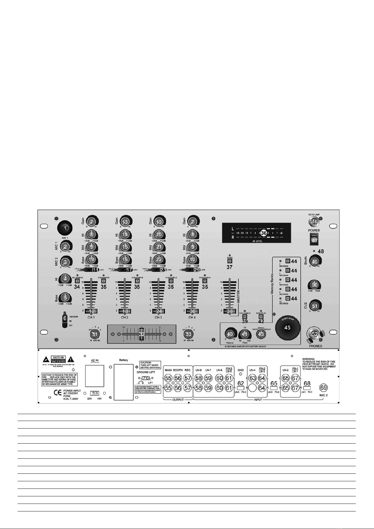
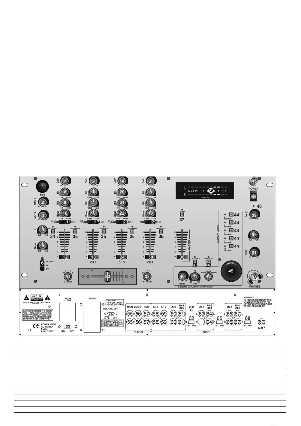
3. La table USB 7100 est fournie avec 3 jeux de jacks de sortie amp. Les jacks de SORTIE PRINCIPALE (55) sont asymétriques et sont utilisés pour connecter sur votre amplificateur princi-
pal. Les jacks de SORTIE REC (56) vous permettent de raccorder un amplificateur supplémentaire.
4. L’entrée MIC 1 (1) (située sur le panneau avant) accepte un connecteur 1/4" ou XLR. L’entrée MIC 2 (69) (située sur le panneau arrière) accepte des connecteurs 1/4". TOUTES les entré-
es acceptent des micros symétriques et asymétriques. Le panneau arrière contient 3 entrées stéréo PHONO/LIGNE (62, 65, 68) et 5 entrées stéréo LIGNE (58, 59, 60, 63, 66). Le commu-
tateur PHONO/LIGNE (62) vous permet de régler l’entrée (61) sur Phono ou Ligne. Le commutateur PHONO/LIGNE (65) vous permet de régler l’entrée (65) sur Phono ou Ligne.
Le commutateur PHONO/LIGNE (68) vous permet de régler l’entrée (67) sur Phono ou Ligne. L’entrée phono accepte uniquement des platines avec une cartouche magnétique. Une VIS DE
MISE A LA MASSE (70), située sur le panneau arrière, vous permet de mettre à la masse vos platines. L’entrée stéréo Ligne accepte toute entrée de niveau de ligne, telle qu’un lecteur de
cd, etc.
5. Des casques peuvent être branchés sur la prise jack CASQUE (52) montée sur le panneau avant.
La table USB 7100 est munie d’une prise jack ECLAIRAGE BNC (46) montée sur le panneau avant. Cette prise jack est utilisée pour une lampe col de cygne.
Utilisation du commutateur de circuit flottant (Ground Lift) :
Suivant la configuration de votre système, le fait d’appliquer la masse peut parfois créer un chemin de signal plus silencieux. Le fait de séparer la masse peut parfois éliminer les circuits de
terre et les ronflements pour créer un chemin de signal plus silencieux.
1. Avec la table de mixage allumée, écoutez le système en mode de veille (aucun signal présent) avec mise à la masse (Commutateur CIRCUIT FLOTTANT (70) en position gauche).
2. Mettez ensuite la table hors tension, avant de déplacer le commutateur CIRCUIT FLOTTANT (70). Séparez la masse en déplaçant le commutateur CIRCUIT FLOTTANT vers la droite.
Remettez la table sous tension et écoutez pour déterminer quelle position fournit un signal exempt de bruits de fond et de ronflements. Maintenez le commutateur CIRCUIT FLOTTANT en
position de masse reliée, si le niveau du bruit reste le même dans les deux positions.
ATTENTION : NE SUPPRIMEZ EN AUCUNE FACON LA MASSE CA SUR LA TABLE DE MIXAGE. LE FAIT DE SUPPRIMER LA MASSE CA PEUT ETRE DANGEREUX.
Fonctionnement :
1. MISE SOUS TENSION : Une fois que vous avez effectué tous les branchements sur votre table de mixage, appuyez sur l’INTERRUPTEUR D’ALIMENTATION (47). L’appareil se met sous ten-
sion et tous les LEDs D’ALIMENTATION (48) s’allument en ROUGE.
2. CANAL 1 : Le commutateur # (17) vous permet de sélectionner l’entrée PHONO 1/LIGNE 1 (67) ou LIGNE 2 (66). Le CURSEUR de GAIN (7) et de CANAL (12) commande le niveau d’en-
trée de ce canal. La coupure EQ (9, 0, 10) vous permet de régler le son.
3. CANAL 2 : Le commutateur # (17) vous permet de sélectionner l’entrée PHONO 2/LIGNE 3 (64) ou LIGNE 4 (63). Le CURSEUR de GAIN (13) et de CANAL (18) commande le niveau d’en-
trée de ce canal. La COUPURE EQ (14, 15, 16) vous permet de régler le son.
4. CANAL 3 : Le commutateur # (23) vous permet de sélectionner l’entrée PHONO 3/LIGNE 5 (61) ou LIGNE 6 (60). Le CURSEUR de GAIN (19) et de CANAL (24) commande le niveau
d’entrée de ce canal. La COUPURE EQ (20,21, 22) vous permet de régler le son.
5. CANAL 4 : Le commutateur # (29) vous permet de sélectionner l’entrée LIGNE 7 (59) ou LIGNE 8 (58). Le CURSEUR de GAIN (25) et de CANAL (30) commande le niveau d’entrée de
ce canal. La COUPURE EQ (26,27, 28) vous permet de régler le son.
6. SECTION CROSSFADER : Le CROSSFADER (32) permet le mixage d’une source dans une autre source. La table USB 7100 contient un crossfader assignable. Les commutateurs ASSIGNER
(31, 33) vous permettent de sélectionner quel canal joue de chaque côté du crossfader Le commutateur ASSIGNER (31) possède 5 positions (DES, 1, 2, 3 ou 4) et vous permet de sélecti-
onner le canal 1, 2, 3 ou 4 pour jouer du côté droit du crossfader. Avec le commutateur ASSIGNER en position DES, ce côté du crossfader sera inactif. Le CROSSFADER (32) de votre
unité est amovible et peut être facilement remplacé en cas de nécessité.
7. SECTION COMMANDE DE SORTIE : Le niveau de la SORTIE PRINCIPALE (55) est commandé par le curseur MASTER (38). Si vous activez le bouton MONO (37) (la LED mono s’allume),
la sortie générale passe en mono. La commande CABINE (49) permet de régler le niveau de la SORTIE CABINE (56). CONSEIL : LA SORTIE CABINE est utilisée par certains disc jockeys
pour connecter des haut-parleurs de contrôle dans leur cabine DJ. Vous pouvez également l’utiliser en tant que seconde sortie ZONE ou AMP.
REMARQUE : La SORTIE REC (57) ne possède pas de commande de niveau. Le niveau est réglé par le gain ou les curseurs de canal du canal sélectionné.
8. SECTION TALK-OVER : Le but de la section talk-over est de permettre d’assourdir le programme en cours de lecture, afin que le micro puisse être entendu par-dessus la musique. Le com-
mutateur MIC/TALKOVER (6) commande MIC 1 et MIC 2 et possède trois positions. Lorsque le commutateur MIC/TALKOVER (6) est sur la position basse. MIC 1, MIC 1 et talk-over sont
désactivés. Lorsque le commutateur MIC/TALK-OVER (6) se trouve sur la position centrale, MIC 1, MIC 2 sont activés, mais talk-over est désactivé. Lorsque le commutateur MIC/TALKOVER
(6) est sur la position haute. MIC 1, MIC 2 et talk-over sont activés et le volume de toutes les sources est baissé de 16 dB, sauf pour les entrées Mic. Les commandes AIGUS (4) et GRA-
VES (5) vous permettent de régler totalement la tonalité de MIC 1 et MIC 2. NIVEAU DE MIC 1 (1) commande le niveau de MIC 1. NIVEAU MIC 2 (2) commande le niveau de MIC 2.
9. SECTION CUE : En connectant un casque sur la prise jack CASQUE (10), vous pouvez surveiller un canal ou la totalité des canaux. Appuyez sur les boutons CUE/SAMPLE pour les canaux
1-4, pour sélectionner le canal ou les canaux devant être surveillés. Leur LEDs respectives s’allument en rouge. Appuyez sur les boutons ASSIGNER CUE/SAMPLE (34, 35). Ces boutons
sont également utilisés pour ajouter des samples (voir fonctionnement du sampler pour plus d’informations). Appuyez sur CUE SAMPLER (39) pour examiner les samples. Utilisez la com-
mande NIVEAU CUE (51) pour régler le volume cue sans affecter l’ensemble du mix. En déplaçant la commande CUE PGM PAM (50) vers la gauche, vous pouvez contrôler le signal cue
assigné. En déplaçant la commande vers la droite, vous pouvez contrôler la sortie PGM (programme).
10. AFFICHAGE : L’AFFICHAGE (36) indique les niveaux droit ou gauche de la sortie MASTER.
Fonctionnement du sampler :
1. INFORMATIONS GENERALES : Le sampler de la table USB 7100 utilise une mémoire RAM dynamique et un contrôleur microprocesseur 16 bits. La largeur de bande totale entraîne une
reproduction du son.
Résultats en reproduction sonore fidèle.
2. INFORMATIONS SUR LA MEMOIRE : La table USB 7100 est équipée de cinq BLOCS DE MEMOIRE (44). Les deux blocs marqués 2 &2 ont une longueur de deux secondes, les deux
blocs marqués 4&4 ont une longueur de quatre secondes et le bloc marqué 12 a une longueur de douze secondes. Ces blocs sont séparés et ne peuvent pas être liés. Vous pouvez stocker
un sample différent dans chaque bloc, mais ils doivent être enregistrés individuellement et ils doivent être lus un par un.
ENREGISTREMENT DE SAMPLE :
1. Placez le SELECTEUR DE MODE (43) sur la position ECRIRE.
Sélectionnez la source que vous souhaitez sampler en appuyant sur le bouton ASSIGNER CUE/SAMPLE (34, 35) souhaité. Sélectionnez le bloc de mémoire dans lequel vous souhaitez enre-
gistrer, en appuyant sur le bouton BLOC MEMOIRE (44) approprié.
2. La table USB 7100 est équipée d’une commande REGISTRE (41) de sampler. Pour définir un sample parfait, placez la commande en position centrale et enregistrez le sample. Durant la
lecture, le fait de soulever ou d’abaisser la commande soulève ou abaisse le registre de lecture du sample. La position centrale correspond à un registre normal.
CONSEIL : Vous pouvez enregistrer un sample avec la commande REGISTRE (41) dans n’importe quelle position. Quelle que soit la position, le son deviendra le son normal. Si vous démar-
rez l’enregistrement d’un sample avec la commande REGISTRE (41) réglée au minimum (ce qui devient à présent votre registre normal) et si vous augmentez le registre jusqu’au maximum,
la vitesse de l’effet de registre doublera. Si vous enregistrez en position maximale puis vous abaissez jusqu'au minimum, vous obtiendrez l’effet inverse.
3. En appuyant sur le bouton MARCHE/ARRET (45), vous démarrez le processus de sampling (le VOYANT DE SAMPLER s’allume en ROUGE). Si vous appuyez une seconde fois, le VOYANT
DE SAMPLER s’éteint. Si vous n’appuyez pas une seconde fois sur le bouton MARCHE/ARRET (45), le processus de sampling s’arrête automatiquement après 2, 4 ou 12 secondes, suivant

11
Copyright U.S. Blaster Europe BV © - Delft - Netherlands
F
le BLOC MEMOIRE (44) sélectionné.
LECTURE DE SAMPLE :
1. Placez le commutateur SELECTEUR DE MODE (43) sur la position UNIQUE ou REPETER.
2. Sélectionnez le bloc de mémoire que vous souhaitez lire, en appuyant sur le bouton BLOC MEMOIRE (44) approprié.
3. Si vous appuyez sur le bouton MARCHE/ARRET (45) avec le commutateur SELECTEUR DE MODE (43) en position UNIQUE, le sampler lit une fois (le VOYANT DE SAMPLER s’allume en
VERT). Chaque fois que vous poussez sur le bouton MARCHE/ARRET (45), le sample redémarre depuis le début. Si vous appuyez rapidement sur le bouton MARCHE/ARRET, vous provo-
quez un effet de bégaiement. Une fois que l’écoute du sample a démarré et si vous n’appuyez pas une seconde fois sur le bouton MARCHE/ARRET (45), le sample est lu jusqu’à la fin puis
il s’arrête (le VOYANT DE SAMPLER s’éteint).
4. Si vous appuyez sur le bouton MARCHE/ARRET (45) avec le SELECTEUR DE MODE (43) en position REPETER, le sample est joué et rejoué continuellement (le VOYANT DE SAMPLER
s’allume en VERT). Le bouton MARCHE/ARRET (45) fonctionne alors en tant qu’interrupteur marche/arrêt. La première poussée démarre le sample, la seconde poussée l’arrête. Le NIVEAU
DE SAMPLER (40) commande le niveau du sample.
ROBO PLAY :
Avec le bouton ROBO PLAY (42) en POSITION DESACTIVE (le VOYANT DE ROBO PLAY est éteint) et le SELECTEUR DE MODE (43) en mode UNIQUE OU REPETE. Si vous appuyez sur le
bouton MARCHE/ARRET (45), le sample est lu avec la source sélectionnée.
Lorsque le bouton ROBO PLAY (42) est en position ACTIVE (le VOYANT ROBO PLAY s’allume en ROUGE), le démarrage du sampler coupe la source sélectionnée. Lorsque le sample s’arrête,
la source est automatiquement réactivée.
BATTERIE DE SECOURS : La table USB 7100 est équipée d’une batterie de secours pour conserver les samples. Pour activer cette fonction, une pile de 9 volts (non incluse) doit être bran-
chée sur le SUPPORT DE BATTERIE (54) situé sur le panneau arrière. Ceci vous permet de stocker les samples dans la mémoire et lorsque l’unité est débranchée, la batterie de secours con-
serve les samples pour un usage futur. Si l’unité est débranchée alors qu’aucune pile n’est connectée, tous les samples sont perdus.
VOYANT DE BATTERIE FAIBLE : Un indicateur de batterie faible est inclus dans le USB 7100. Lorsque vous changez la pile, veillez à ce que l’unité soit branchée et qu’elle soit sous tension.
Dans le cas contraire, les éléments contenus dans la mémoire seront perdus. Le voyant de batterie faible est allumé lorsque le voyant LED du bloc de mémoire sélectionné clignote. Le voyant
LED clignote également lorsqu’aucune pile n’est connectée sur l’unité
Caractéristiques
ENTREES :
Micro DJ 1,5 mV 2 kOhm symétrique
Phono 3 mV 47 kOhm
Ligne 150 mV 27 kOhm
Aux 150 mV 27 kOhm
SORTIES :
Main/Aux 0 dB 1 V 400 Ohm
Max 20 V Crête à crête
Rec 225 Mv 5 kOhm
MIC 1&MIC 2 :
Micro DJ 1,5 mV 2 kOhm symétrique
Graves ± 12 dB
Aigus ± 12 dB
GENERALITES :
Fréquence de réponse 20 Hz-20 kHz +/-2 dB
Distorsion 0,02%
Rapport S/B supérieur à 80 dB
Atténuation de talk-over ?16 dB
Impédance de casque 16 Ohm
Alimentation 115/230 V 50/60 Hz 10 W
Dimensions 19"l x 4"h x 9" p
Poids 4,6 kg

INSTRUCTION MANUAL - PROFESSIONAL MIXER - USB 7100
Eigenschappen:
* 4 Stereokanalen
* Geavanceerde art-cuesectie
* 3 Omschakelbare phono/line-ingangen, 5 line-ingangen en 2 microfooningangen
* 3-bands EQ (LAAG MIDDEN HOOG) voor elk kanaal
* Talk-over
* Master-, booth- en opnameuitgangen
* Digitale sampler met 5 geheugenbanken
* Batterijbackup voor opslag samples
Aansluitingen:
1. Alvorens het netsnoer aan te sluiten, dient u te controleren of de SPANNINGSSELECTIESCHAKELAAR (53) op de juiste spanning is ingesteld.
OPMERKING: Dit product is dubbel geïsoleerd en mag niet worden geaard.
2. Controleer of de AAN/UIT-SCHAKELAAR (47) in de uit-positie staat. De AAN/UIT-LED (48) zal niet branden.
3. De USB 7100 wordt geleverd met 3 jack-sets voor de versterkersuitgang. De HOOFDUITGANGSJACKS (55) zijn niet gebalanceerd en worden gebruikt voor het aansluiten van de hoofdver-
sterker. Met de REC-UITGANGSJACKS (56) kunt u een extra versterker aansluiten.
4. Op de MIC 1-ingang (1, op het voorpaneel) kunt u 1/4"- of XLR-connectors aansluiten. Op de MIC 2-ingang (69, op het achterpaneel) kunt u 1/4"-connectors aansluiten. Op alle ingangen
kunnen zowel gebalanceerde als niet-gebalanceerde microfoons worden aangesloten. Op het achterpaneel bevinden zich 3 stereo PHONO/LINE-ingangen (62, 65, 68) en 5 stereo LINE-
ingangen (58, 59, 60, 63, 66). Met de PHONO/LINE-SCHAKELAAR (62) kunt u de ingang (61) op PHONO/LINE instellen. Met de PHONO/LINE-SCHAKELAAR (65) kunt u de ingang (65)
op PHONO/LINE instellen. Met de PHONO/LINE-SCHAKELAAR (68) kunt u de ingang (67) op PHONO/LINE instellen. De PHONO-ingangen zijn alleen geschikt voor draaitafels met een
magnetische cassette. Op het achterpaneel bevindt zich een AARDINGSSCHROEF (70) waarmee u de draaitafels kunt aarden. Op de stereo Line-ingangen kan Line-apparatuur worden
aangesloten, zoals cd-spelers, enzovoort.
5. Hoofdtelefoons kunnen worden aangesloten op de HOOFDTELEFOONJACK (52) op het voorpaneel. Op het voorpaneel van de USB 7100 bevindt zich een BNC-LICHTJACK (46). Deze jack
kan worden gebruikt voor klemkikkers.
Gebruik van de aardingsschakelaar:
Afhankelijk van de systeemconfiguratie, kunt u een rustiger signaalpad creëren door de apparatuur te aarden. Soms kan het opheffen van de aarding aardingslussen en brommen voorkomen
en een rustiger signaalpad creëren.
1. Schakel de mixer in en luister naar het systeem in idle-modus (dat wil zeggen zonder signaal) terwijl de aarding is ingeschakeld (de AARDEOPHEFFINGSSCHAKELAAR (70) staat op de
linkerpositie).
2. Schakel de apparatuur uit en beweeg de AARDEOPHEFFINGSSCHAKELAAR (70). Hef de aarding op door de AARDEOPHEFFINGSSCHAKELAAR naar rechts te bewegen. Schakel de appa-
ratuur weer in en ga na in welke positie achtergrondruis en gebrom verdwijnen. Laat de AARDEOPHEFFINGSSCHAKELAAR op de aardingspositie staan als het ruisniveau in beide posities
gelijk blijft.
WAARSCHUWING: HEF NOOIT DE WISSELSPANNINGSAARDING VAN DE POWER MIXER OP. OPHEFFING VAN DE WISSELSPANNINGSAARDING KAN GEVAARLIJK ZIJN.
Bediening:
1. INSCHAKELEN: Nadat u alle apparatuur op de mixer heeft aangesloten, drukt u op de AAN/UIT-SCHAKELAAR (47). De mixer wordt ingeschakeld en de AAN/UIT-LED (48) zal ROOD oplich-
ten.
2. KANAAL 1: Met de schakelaar (17) kunt u de PHONO 1/LINE 1-ingang (67) of de LINE 2-ingang (66) selecteren. Met de INGANGSGEVOELIGHEID (7) en de KANAALSCHUIF (12) regelt u
het ingangsniveau van dit kanaal. Met EQ CUT (9, 0, 10) kunt u het geluid instellen.
3. KANAAL 2: Met de schakelaar (17) kunt u de PHONO 2/LINE 3-ingang (64) of de LINE 4-ingang (63) selecteren. Met de INGANGSGEVOELIGHEID (13) en de KANAALSCHUIF (18) regelt
u het ingangsniveau van dit kanaal. Met EQ CUT (14, 15, 16) kunt u het geluid instellen.
4. KANAAL 3: Met de schakelaar (23) kunt u de PHONO 3/LINE 5-ingang (61) of de LINE 6-ingang (60) selecteren. Met de INGANGSGEVOELIGHEID (19) en de KANAALSCHUIF (24) regelt
u het ingangsniveau van dit kanaal. Met EQ CUT (20, 21, 22) kunt u het geluid instellen.
5. KANAAL 4: Met de schakelaar (29) kunt u de LINE 7-ingang (59) of de LINE 8-ingang (58) selecteren. Met de INGANGSGEVOELIGHEID (25) en de KANAALSCHUIF (30) regelt u het
ingangsniveau van dit kanaal. Met EQ CUT (26, 27, 28) kunt u het geluid instellen.
6. CROSSFADER-SECTIE: Met de CROSSFADER (32) kunt u verschillende bronnen met elkaar mixen. De USB 7100 beschikt over een toewijsbare crossfader. Met de TOEWIJZINGSSCHAKE-
LAARS (31, 33) kunt u bepalen welk kanaal aan welke kant van de crossfader wordt afgespeeld. De TOEWIJZINGSSCHAKELAAR (31) heeft 5 instellingen (uit, 1, 2, 3 of 4), waarmee u
kunt aangeven welke kanalen aan de rechterkant van de crossfader moeten worden afgespeeld. Als de TOEWIJZINGSSCHAKELAAR in de uit-positie staat, dan is de linker-/rechterkant van
de crossfader niet actief. De CROSSFADER (32) kan eventueel eenvoudig worden vervangen.
7. SECTIE VOOR UITGANGSREGELING: Het niveau van de HOOFDUITGANG (55) wordt geregeld met de MASTER-SCHUIF (38). Als u de MONO-KNOP (37) activeert (de mono-LED zal gaan
branden), worden de uitgangen mono. Met de BOOTH-REGELING (49) regelt u het niveau van de BOOTH-UITGANG (56). TIP: Sommige DJ's gebruiken de BOOTH-UITGANG voor monitor-
speakers in hun DJ-booth. U kunt de uitgang tevens gebruiken als tweede ZONE- of AMP-UITGANG. OPMERKING: De REC-UITGANG (57) heeft geen niveauregeling. Het niveau wordt
ingesteld met de ingangsgevoeligheid of kanaalschuiven van het geselecteerde kanaal.
8. TALK-OVERSECTIE: Met de talk-oversectie kunt u de afgespeelde muziek muten, zodat de microfoon hoorbaar wordt. Met de MIC/TALK-OVERSCHAKELAAR (6) regelt u MIC 1 en MIC 2.
Deze schakelaar heeft drie instellingen. Als de MIC/TALK-OVERSCHAKELAAR (6) op de onderste positie staat, dan zijn MIC 1, MIC 2 en talk-over uitgeschakeld. Als de MIC/TALK-OVER-
SCHAKELAAR (6) in de middenpositie staat, dan worden MIC 1 en 2 ingeschakeld en talk-over uitgeschakeld. Als de MIC/TALK-OVERSCHAKELAAR (6) op de bovenste positie staat, dan
worden MIC 1, MIC 2 en talk-over ingeschakeld (de microfooningangen worden met 16dB verlaagd). Met de TREBLE- (4) en BASREGELING (5) kunt u de toon van MIC 1 en MIC 2 rege-
len. MIC 1-NIVEAU (1) regelt het niveau van MIC 1. MIC 2-NIVEAU (2) regelt het niveau van MIC 2.
9. CUE-SECTIE: Als u een hoofdtelefoonset op de HOOFDTELEFOONJACK (52) aansluit, kunt u alle kanalen monitoren. Druk op de CUE-/SAMPLETOEWIJZINGSKNOPPEN (35) voor de kana-
len 1-4 om de te monitoren kanalen te selecteren. De respectievelijke LED-indicators zullen rood oplichten. U kunt de CUE-/SAMPLETOEWIJZINGSKNOPPEN (34, 35) ook indrukken om
samples toe te voegen (zie 'Samplerbediening' voor meer informatie). Druk op de CUE-SAMPLER (39) om de samples te monitoren. Met de CUE-NIVEAUREGELING (51) kunt u het cue-
volume instellen zonder de hele mix te beïnvloeden. Als u de CUE PGM PAM-REGELING (50) naar links beweegt, kunt u het toegewezen cue-signaal monitoren. Als u de regeling naar
rechts beweegt, monitort u de PGM- of programmauitgang.
10. SCHERM: Het scherm (36) geeft de niveaus links en rechts op de MASTER-UITGANG weer.
Samplerbediening:
1. ALGEMENE INFORMATIE: De USB 7100-sampler beschikt over dynamisch RAM-geheugen en een 16-bits microprocessoraansturing. De grote bandbreedte zorgt voor een realistische
geluidsweergave.
2. GEHEUGENINFORMATIE: De USB 7100 is voorzien van vijf GEHEUGENBANKEN (44). De twee banken 2&2 hebben een lengte van twee seconden, de twee banken 4&4 hebben een leng-
te van vier seconden en bank 12 heeft een lengte van 12 seconden. Deze banken zijn gescheiden en kunnen niet aan elkaar worden gekoppeld. U kunt in elke bank een andere sample
opslaan. De samples moeten echter apart worden opgenomen en er kan slechts één sample tegelijkertijd worden afgespeeld.
SAMPLEOPNAME:
1. Zet de MODUSSELECTIESCHAKELAAR (43) in de SCHRIJFPOSITIE.
Selecteer de te samplen bron door de betreffende CUE-/SAMPLETOEWIJZINGSKNOP (34, 35) in te drukken. Selecteer de geheugenbank waarin u wilt opnemen door de betreffende GEHEU-
GENBANKKNOP (44) in te drukken.
2. De USB 7100 is voorzien van een SAMPLERTOONHOOGTEREGELING (41). Om een perfecte sample te krijgen, stelt u de regeling in op de middenpositie en neemt u vervolgens de sample
op. Tijdens het afspelen kunt u de toonhoogte van de afgespeelde sample met de regeling verhogen of verlagen. Op de middenpositie wordt de sample op normale toonhoogte afgespeeld.
HINT: Bij het opnemen van samples kunt u de TOONHOOGTEREGELING (41) op elke gewenste positie zetten. Deze positie zal vervolgens als de 'normale' positie worden geïnterpreteerd.
Als u bij het opnemen van een sample de TOONHOOGTEREGELING (41) op de minimumpositie zet (die vanaf dat moment de normale toonhoogte aangeeft), dan kunt u de afspeelsnelheid
verdubbelen door de toonhoogte op de maximumpositie te zetten. Als u een sample op de maximumpositie opneemt en de regeling vervolgens op de minimumpositie zet, gebeurt precies
het tegenovergestelde.
12 Copyright U.S. Blaster Europe BV © - Delft - Netherlands
NL

3. Als u op de START/STOP-KNOP (45) drukt, wordt de samplingprocedure in gang gezet (de SAMPLERINDICATOR licht ROOD op). Als u de SAMPLERINDICATOR nogmaals indrukt, wordt de
procedure afgebroken. Als u de START/STOP-KNOP (45) geen tweede keer indrukt, dan stopt de samplingprocedure automatisch na 2, 4 of 12 seconden, afhankelijk van de geselecteerde
GEHEUGENBANK (44).
SAMPLE AFSPELEN:
1. Zet de MODUSSELECTIESCHAKELAAR (43) op de SINGLE- of REPEATPOSITIE.
2. Selecteer de geheugenbank die u wilt afspelen door de betreffende GEHEUGENBANKKNOP (44) in te drukken.
3. Als u de START/STOP-KNOP (45) indrukt terwijl de MODUSSELECTIESCHAKELAAR op de SINGLE-POSITIE staat, dan wordt de sample één keer afgespeeld (de SAMPLERINDICATOR licht
GROEN op). Bij elke druk op de START/STOP-KNOP (45) wordt de sample opnieuw afgespeeld. Als u de START/STOP-KNOP snel achter elkaar indrukt, krijgt u een 'stottereffect'. Als de
sample wordt afgespeeld en u de START/STOP-KNOP (45) geen tweede keer indrukt, dan wordt de sample helemaal afgespeeld en niet herhaald (de SAMPLERINDICATOR gaat uit).
4. Als u de START/STOP-KNOP (45) indrukt terwijl de MODUSSELECTIESCHAKELAAR (43) op de REPEATPOSITIE staat, dan wordt de sample continu herhaald (de SAMPLERINDICATOR licht
GROEN op). De START/STOP-KNOP (45) werkt als een aan/uit-schakelaar. Bij de eerste druk wordt de sample gestart en bij de tweede druk wordt de sample gestopt. Met het SAMPLER-
NIVEAU (40) regelt u het niveau van de sample.
ROBOPLAY:
Zet de ROBOPLAY-KNOP (42) in de UIT-POSITIE (de ROBOPLAY-INDICATOR gaat uit) en de MODUSSELECTIESCHAKELAAR (43) in de SINGLE- of REPEATMODUS. Als u nu op de
START/STOP-KNOP (45) drukt, wordt de sample tegelijkertijd met de geselecteerde bron afgespeeld.
Als de ROBOPLAY-KNOP (42) in de AAN-POSITIE staat (de ROBOPLAY-INDICATOR licht ROOD op), dan wordt de geselecteerde bron gemutet als de sampler wordt gestart. Als de sample
eindigt, wordt de bron automatisch opnieuw ingeschakeld.
BACKUPBATTERIJ: De USB 7100 beschikt over een backupbatterij voor de opslag van de samples. Om deze functionaliteit te activeren, dient u een 9 volt-batterij (niet meegeleverd) op de
BATTERIJHOUDER (54) op het achterpaneel aan te sluiten. Hiermee kunt u samples in het geheugen opslaan. Ook als de eenheid wordt losgekoppeld, zorgt de backupbatterij ervoor dat de
samples voor toekomstig gebruik worden opgeslagen. Als de eenheid wordt losgekoppeld en er geen batterij is aangesloten, dan gaan alle samples verloren.
INDICATOR VOOR LAGE BATTERIJSPANNING: De USB 7100 bevat een indicator voor lage batterijspanning. Controleer bij het vervangen van de batterij of de eenheid is aangesloten en inge-
schakeld. Als u dit niet doet, dan zal het geheugen worden gewist. De indicator voor lage batterijspanning is aan als de LED van de geselecteerde geheugenbank knippert. De LED knippert
ook als er geen batterij op de eenheid is aangesloten.
13
Copyright U.S. Blaster Europe BV © - Delft - Netherlands
NL
Specificaties
INGANGEN:
DJ-microfoon 1,5mV 2KOhm gebalanceerd
Phono 3mV 47KOhm
Line 150 mV 27KOhm
Aux 150 mV 27KOhm
UITGANGEN:
Main/Aux 0dB 1V 400Ohm
Max 20V Peak to peak
Rec 225Mv 5KOhm
MIC 1 & MIC 2:
DJ-microfoon 1,5mV 2KOhm gebalanceerd
Bas ±12dB
Hoog ±12dB
ALGEMEEN:
Frequentierespons 20Hz-20KHz +/-2dB
Vervorming 0,02%
S/R-verhouding beter dan 80dB
Demping talk-over _16dB
Impedantie hoofdtelefoon 16Ohm
Stroombron 115/230V 50/60Hz 10W
Afmetingen 123cm(b) x 10cm (h) x 23cm (d)
Gewicht 4,6 kg

NSTRUCTION MANUAL - PROFESSIONAL MIXER - USB 7100
Caratteristiche:
*. 4 canali stereofonici
*. Parte per le informazioni di controllo a livello di eccellenza.
*. 3 entrate convertibili fono/linea, 5 entrate di linea e 2 entrate per microfoni
*. Equalizzazione a tre bande (bassa, media e alta) per ciascun canale
*. Voce sovrastante
*. Uscite: principale, per il bancone e per la registrazione
*. Campionatore digitale con 5 memorie di banco
*. Salvaguardia a batteria per la conservazione dei campioni
Connessioni:
1. Prima di collegare il cavo di alimentazione, assicurarsi che il commutatore VOLTAGE SELECTOR (53) sia predisposto alla tensione corretta.
NOTA: Questo prodotto presenta una doppia isolazione e non è previsto per essere collegato alla terra.
2. Assicurarsi che l’interruttore POWER (47) si trovi in posizione "spento" (Off). L’indicatore POWER LED (48) sarà spento.
3. Il DJ924 viene fornito con 3 gruppi di prese di uscita per amplificatori. Le prese di uscita principali MAIN OUTPUT (55) sono sbilanciate e impiegate per la connessione all’amplificatore
principale. Le prese d’uscita per la registrazione REC OUTPUT (56) permettono l’allacciamento di un amplificatore addizionale.
4. L’entrata per microfono MIC 1 (1) (che si trova sul pannello frontale) accetta un connettore di tipo _" o XLR. L’entrata per microfono MIC 2 (69) (che si trova sul pannello posteriore) accet-
ta connettori di tipo _". E tutte accettano microfoni bilanciati e sbilanciati. Sul pannello posteriore sono presenti 3 entrate PHONO/LINE (62,65,68) e 5 entrate LINE stereo
(58,59,60,63,66). Il commutatore tra fono e linea PHONO/LINE SWITCH (62) consente di predisporre l’entrata (61) come linea per fono. Il commutatore tra fono e linea PHONO/LINE
SWITCH (65) consente di predisporre l’entrata (65) come linea per fono.
Il commutatore tra fono e linea PHONO/LINE SWITCH (68) consente di predisporre l’entrata (67) come linea per fono. Le entrate fono accettano unicamente piastre giradischi con fonorivela-
tore magnetico. Una vite GROUND SCREW (70) per la messa a terra della piastra giradischi si trova sul pannello posteriore. Le entrate stereo di linea accettano entrate di linea di qualsia-
si livello come quelle provenienti da un lettore CD ed altre.
5. La cuffia o gli auricolari possono essere collegati alla presa HEADPHONE (52) montata sul pannello frontale.
L’USB 7100 è fornito con una presa BNC LIGHT (46) sul pannello frontale. Questa presa è disponibile per una lampada a collo d'oca.
Utilizzazione del commutatore di sollevamento del fondo (Ground Lift):
A seconda del tipo di configurazione del sistema, l’applicazione del commutatore Ground Lift determinerà talvolta un percorso più quieto del segnale. Se si solleva il soglio ambientale si pos-
sono infatti eliminare circuitazioni di fondo e ronzii, determinando in tal modo un percorso del segnale meno disturbato.
1. Quando il mixer è acceso, si ascolti il sistema in modo di riposo (ovvero senza alcun segnale presente) con la funzione Ground applicata (commutatore GROUND LIFT SWITCH (70) posizio-
nato a sinistra).
2. Spegnere l’apparecchio prima di spostare la posizione del commutatore GROUND LIFT SWITCH (70). Sollevare il soglio ambientale posizionando il commutatore GROUND LIFT SWITCH
verso destra. Riaccendere il sistema e determinare la posizione per cui si possa ottenere un segnale sprovvisto di rumore di fondo e ronzii. Mantenere il commutatore GROUND LIFT
SWITCH nella posizione iniziale nel caso che il livello di rumore permanga lo stesso in tutte le posizioni.
AVVERTIMENTO: NON COLLEGARE IN NESSUN MODO IL CONDUTTORE DI TERRA DELLA LINEA DI RETE DEL MIXER DI POTENZA. IL COLLEGAMENTO DEL CONDUTTORE DI TERRA
DELLA LINEA DI RETE PUÒ DAR LUOGO A PERICOLI:
Operazione:
1. ACCENSIONE: Una volta effettuati tutti i collegamenti dei vari dispositivi al mixer, premere l’interruttore POWER SWITCH (47). L’apparecchio si accenderà e l’indicatore POWER LED (48) si
illuminerà di rosso.
2. CANALE 1: il commutatore #(17) permette di selezionare l’entrata PHONE 1/LINE 1 (67) o quella LINE 2 (66). Il guadagno GAIN (7) e il potenziomentro CHANNEL SLIDE (12) controllano
il livello d’entrata di questo canale. Il comando EQ CUT (9,0,10) permette la regolazione del suono.
3. CANALE 2: il commutatore #(17) permette di selezionare l’entrata PHONE 2/LINE 3 (64) o quella LINE 4 (63). Il guadagno GAIN (13) e il potenziomentro CHANNEL SLIDE (18) controlla-
no il livello d’entrata di questo canale. Il comando EQ CUT (14,15,16) permette la regolazione del suono.
4. CANALE 3: il commutatore #(23) permette di selezionare l’entrata PHONE 3/LINE 5 (61) o quella LINE 6 (60). Il guadagno GAIN (19) e il potenziomentro CHANNEL SLIDE (24) controlla-
no il livello d’entrata di questo canale. Il comando EQ CUT (20,21,22) permette la regolazione del suono.
5. CANALE 4: il commutatore #(29) permette di selezionare l’entrata LINE 7 (59) o quella LINE 8 (58). Il guadagno GAIN (25) e il potenziomentro CHANNEL SLIDE (30) controllano il livello
d’entrata di questo canale. Il comando EQ CUT (26,27,28) permette la regolazione del suono.
6. SEZIONE DELL’ATTENUATORE INCROCIATO (CROSSFADER): L’attenuatore incrociato CROSSFADER (32) consente il missaggio di una fonte sonora in un’altra. Il DJ924 presenta un attenu-
atore incrociato attribuibile. I commutatori ASSIGN (31,33) consentono la selezione dell’attribuzione dei canali da riprodurre tramite ciascun lato dell’attenuatore incrociato. Il commutatore
ASSIGN (31) dispone di 5 predisposizioni (OFF (=disattivato), 1, 2, 3 o 4) e consente di selezionare il canale (1, 2, 3 o 4) da riprodurre tramite il lato destro dell’attenuatore incrociato).
Quando il commutatore ASSIGN è in posizione OFF (disattivato), il corrispondente lato dell’attenuatore incrociato resterà inattivo. L'attenuatore incrociato CROSSFADER (32) dell'apparec-
chio è rimuovibile e, in caso di necessità, può essere facilmente sostituito.
7. SEZIONE DI CONTROLLO DELL’USCITA: Il livello dell’uscita principale MAIN OUTPUT (55) è controllato dal potenziometro principale MASTER (38). Se si attiva il commando MONO (37) (si
accende allora la spia LED « Mono »), si rende monofonica l’uscita totale. Il commando di bancone BOOTH (49) regola il livello dell’uscita per il bancone BOOTH OUTPUT (56). SUGGERI-
MENTO: L’uscita per il bancone BOOTH OUTPUT viene utilizzata da alcuni DJ per operare casse di monitoraggio sul loro bancone di DJ. Si può inoltre utilizzarla come una seconda uscita
di zona ZONE o per amplificatore AMP.
NOTA: L’uscita di registrazione REC OUTPUT (57) non dispone di alcun controllo di livello. Il livello viene regolato mediante i comandi di guadagno o i potenziometri del canale selezionato.
8. SEZIONE DELLA VOCE SOVRASTANTE: Il proposito della sezione della voce sovrastante è quello di permettere il silenziamento del programma in riproduzione, per consentire l’ascolto del
microfono sopra la musica. Il commutatore fra microfono e voce sovrastante MIC/TALKOVER SWITCH (6) controlla i microfoni MIC 1 e MIC 2 e presenta tre predisposizioni. Quando il
commutatore MIC/TALKOVER SWITCH (6) si trova nella posizione inferiore, i microfoni MIC 1 e MIC 2, nonché la voce sovrastante, sono disattivati. Quando il commutatore MIC/TALK-
OVER SWITCH (6) si trova posizionato al centro, i microfoni MIC 1 e MIC 2 sono attivi, ma il dispositivo di voce sovrastante è disattivato. Quando il commutatore MIC/TALKOVER SWITCH
(6) si trova nella posizione superiore, i microfoni MIC 1 e MIC 2, nonché la funzione della voce sovrastante sono attivati, mentre i livelli acustici di tutte le fonti sonore, ad eccezione dell’-
entrata per microfono, vengono attenuati di 16 dB. I comandi di acuti e bassi TREBLE (4) e BASS (5) permettono la piena regolazione del tono dei microfoni MIC 1 e MIC 2. Il comando
MIC 1 LEVEL (1) controlla il livello di MIC 1, mentre quello MIC 2 LEVEL (2) controlla il livello di MIC 2.
9. SEZIONE DELLE INFORMAZIONI DI CONTROLLO: Se si collega una cuffia alla presa HEADPHONE (52), si può monitorare uno qualsiasi fra tutti i canali. Premere i pulsanti per l’attribuzio-
ne delle informazioni di controllo e campionature CUE/SAMPLE ASSIGN (35) per i canali 1-4 per selezionare il canale o i canali da monitorare: le loro corrispondenti spie LED si illumine-
ranno in rosso. Premendo i pulsanti per l’attribuzione delle informazioni di controllo e campionature CUE/SAMPLE ASSIGN (34,35) si possono inoltre aggiungere campionature (vedere l’o-
perazione di campionatura per ulteriori dettagli). Premere il pulsante di campionatura delle informazioni di controllo CUE SAMPLER (39) per monitorare le campionature. Utilizzare il coman-
do del livello delle informazioni di controllo CUE LEVEL (51) per regolare il volume delle informazioni di controllo senza influire sul missaggio totale. Spostando il comando CUE PGM PAM
(50) verso sinistra si potrà monitorare il segnale delle informazioni di controllo attribuito. Spostando il comando verso destra si monitorerà l’uscita PGM (programma).
10. VISUALIZZAZIONE: La visualizzazione DISPLAY (36) indica entrambi i livelli, sinistro e destro, dell’uscita princiapale MASTER.
Operazione di campionatura:
1. INFORMAZIONE GENERALE: Il campionatore dell’USB 7100 utilizza della memoria dinamica DRAM e un controllore a microprocessore da 16 bit. L’intera banda passante è dedicata alla
riproduzione sonora.
Il risultato che si ottiene è una riproduzione sonora realistica.
2. INFORMAZIONI RELATIVE ALLE MEMORIA: L’USB 7100 viene fornito con 5 banchi di memoria MEMORY BANKS (44). I due banchi marcati 2&2 presentano una lunghezza di due secon-
di; gli altri due marcati 4&4 presentano una lunghezza di quattro secondi, mentre quello marcato 12 presenta una lunghezza di dodici secondi. Questi banchi sono separati e non possono
essere collegati assieme. Si può memorizzare un campione diverso in ciascun banco, ma questi campioni devono essere registrati singolarmente e riprodotti uno alla volta.
REGISTRAZIONI DI CAMPIONI:
1. Posizionare il selettore di modalità MODE SELECTOR (43) su WRITE (scrivere).
14 Copyright U.S. Blaster Europe BV © - Delft - Netherlands
I

Selezionare la fonte da cui estrarre il campione premendo l’appropriato pulsante di attribuzione delle informazioni di controllo e campionature CUE/SAMPLE ASSIGN (34,35). Selezionare il
banco memoria su cui si vuole registrare premendo l’appropriato pulsante MEMORY BANK (44).
2. Il DJ924 è fornito con un controllo di altezza del tono di campionatura PITCH (41). Per ottenere una campionatura perfetta, predisporre il comando in posizione centrale e registrare il cam-
pione. Durante la riproduzione, se si solleva o abbassa il comando, si solleva o abbassa l’altezza del tono della lettura del campione. La posizione centrale resterà definita come altezza di
tono normale.
SUGGERIMENTO: Si può registrare un campione con il comando di altezza di tono PITCH (41) posizionato in un qualsiasi modo. Quale sia tale posizione, questa diverrà il riferimento per un
suono normale. Se si avvia la registrazione di un campione con il comando di altezza di tono PITCH (41) predisposto al minimo (e tale posizione diverrà dunque il riferimento come altezza
di tono 'normale'), se si aumenta tale comando al massimo, l’effetto dell'altezza di tono raddoppierà di velocità. Se si registra al livello massimo e si abbassa a quello minimo, succederà
esattamente l’opposto.
3. Picchiettando sul pulsante di avvio/arresto START/STOP (45), si inizia il processo di campionatura (e la spia di campionatura SAMPLER INDICATOR si illuminerà in rosso). Picchiettando
ancora sullo stesso pulsante, la spia SAMPLER INDICATOR si spegnerà. Se non si picchietta una seconda volta sul pulsante START/STOP (45), il processo di campionatura si arresterà
dopo 2, 4 o 12 secondi, secondo il tipo di banco di memoria MEMORY BANK (44) che è stato selezionato.
LETTURA DEL CAMPIONE:
1. Posizionare il selettore di modalità MODE SELECTOR (43) su SINGLE (unico) o REPEAT (ripetizione).
2. Selezionare il banco memoria su cui si vuole registrare premendo l’appropriato pulsante MEMORY BANK (44).
3. Se si picchietta sul pulsante di avvio/arresto START/STOP (45) quando il selettore di modalità MODE SELECTOR (43) si trova in posizione SINGLE (unico), la compionatura verrà letta una
sola volta (e la spia SAMPLE INDICATOR si illuminerà in verde). Ad ogni pressione sul pulsante START/STOP (45), il processo riavvierà la campionatura dall’inizio. Una pressione rapida sul
pulsante START/STOP provocherà un effetto di "balbuzie". Una volta avviata la lettura della campionatura e se non si preme una seconda volta il pulsante START/STOP (45), la campiona-
tura verrà letta fino alla fine e quindi la riproduzione si arresterà (e la spia SAMPLER INDICATOR si spegnerà).
4. Se si picchietta sul pulsante di avvio/arresto START/STOP (45) quando il selettore di modalità MODE SELECTOR (43) si trova in posizione REPEAT (ripetizione), la compionatura verrà letta
e riletta senza interruzione (e la spia SAMPLE INDICATOR si illuminerà in verde). Il pulsante START/STOP (45) si comporterà come un interruttore accaso/spento. La prima pressione eser-
citata su questo pulsante avvia la campionatura, la seconda l’arresterà. Il pilotaggio è attuato dal comando di livello della campionatura SAMPLER LEVEL (40).
LETTURA ROBOTIZZATA (ROBO PLAY):
Predisporre il pulsante ROBO PLAY (42) sulla posizione OFF, disattivato (la spia ROBO PLAY INDICATOR è spenta) e il commutatore di selezione di modalità MODE SELECTOR (43) sia su
SINGLE (unico), sia su REPEAT (ripetizione). Se si preme il pulsante START/STOP (45) si riproduce la campionatura assieme alla fonte selezionata.
Quando il commutatore ROBO PLAY (42) è in posizione ON, attivato (la spia ROBO PLAY INDICATOR è accesa in rosso), se si avvia il campione si silenzia la fonte selezionata. Quando term-
ina la lettura del campione, la fonte si riattiva automaticamente.
SALVAGUARDIA A BATTERIA: L’USB 7100 è fornito di una salvaguardia a batteria per la conservazione dei campioni. Per attivare questa caratteristica, una batteria da 9 Volt (non fornita a
corredo) dev’essere collegata a un contenitore BATTERY HOLDER (54) che si trova sul pannello posteriore. Questo consente di registrare campioni in memoria e, quando si stacca l'apparec-
chio dalla rete, la salvaguardia a batteria conserva i campioni per un'utilizzazione ulteriore. Se l'apparecchio viene staccato e che non vi è alcuna batteria di salvaguardia, tutti i campioni ver-
ranno persi.
INDICATORE DI BATTERIA ESAURITA: Nell’USB 7100 è incluso un indicatore di batteria esaurita. Quando si sostituisce la batteria, assicurarsi che l’apparecchio è collegato alla rete e che il
pulsante acceso/spento si trova in posizione ON, acceso. Se non si segue questa procedura, il contenuto della memoria andrà perso. L’indicatore di batteria esaurita è acceso quando lampeg-
gia la spia LED del banco di memoria selezionato. Questo LED lampeggia pure quando non è stata installata nessuna batteria.
15
Copyright U.S. Blaster Europe BV © - Delft - Netherlands
I
ENTRATE:
DJ Mic 1,5 mV 2 Kohm bilanciata
Phono 3 mV 47 Kohm
Line 150 mV 27 Kohm
Aux 150 mV 27 Kohm
USCITE:
Main/Aux 0 dB 1 V 400 ohm
Massimo 20 V picco a picco
Rec 225 Mv 5 Kohm
MIC 1 & MIC 2:|
DJ Mic 1,5 mV 2 Kohm bilanciata
Bassi. 2 dB
Acuti. ±12 dB
GENERALI
Risposta in frequenza 20 Hz – 20 KHz +/- 2 dB
Distorsione 0,02%
Rapporto segnale/rumore. migliore di 80 dB
Attenuazione di voce sovrastant - 16 dB
Impedenza cuffia/auricolari. 16 ohm
Alimentazione elettrica 115/230 V 50/60 Hz 10 W
Dimensioni 44,4 cm (larghezza) x 10,2 cm (altezza) x 22,9 cm
(profondità)
Peso. 4,6 kg

NSTRUCTION MANUAL - PROFESSIONAL MIXER - USB 7100
Características:
*. 4 canales estéreo
*. Sección de pista de última tecnología
*. 3 entradas Phono/línea convertible, 5 entradas de línea y 2 de micrófonos
*. Ecualizador de 3 bandas (BAJA MEDIA ALTA) para cada canal
*. Talkover (Superposición de voz)
*. Salidas maestra, cabina y grabación
*. Muestreador digital con 5 bancos de memoria
*. Pila de respaldo para mantenimiento de muestras
Conexiones
1. Antes de desconectar el cable de alimentación de red eléctrica, asegúrese que el interruptor de SELECCIÓN DE TENSIÓN (53) esté en la tensión correcta.
NOTA: Este producto tiene doble aislamiento y no necesita conexión a tierra.
2. Asegúrese que el interruptor de Encendido (47) esté en la posición desconectado. El indicador LED DE ENCENDIDO (48) estará apagado.
3. El equipo Dj924 se suministra con 3 conjuntos de clavijas de salida de amplificación. Las clavijas de SALIDA PRINCIPAL (55) no están balanceadas y se utilizan para conectar el amplifi-
cador principal. Las clavijas de SALIDA DE GRABACIÓN (56) le permiten conectar un amplificador adicional.
4. La entrada de MICRÓFONO 1 (1) (en el panel frontal) admite un conector de 1/4" o XLR. La entrada de MICRÓFONO 2 (69) (en el panel posterior) admite conectores de 1/4". Todas
admiten micrófonos balanceado y no balanceado. En la parte posterior hay 3 entradas estéreo PHONO/LÍNEA (62, 65, 68) y 5 entradas estéreo de LÍNEA (58,59,60,63,66) . El INTER-
RUPTOR PHONO/LÍNEA (62) permite seleccionar la entrada (61) como entrada de línea phono. El INTERRUPTOR PHONO/LÍNEA (65) permite seleccionar la entrada (65) como entrada
Phono o línea.
El INTERRUPTOR PHONO/LÍNEA (68) permite seleccionar la entrada (67) como entrada Phono o línea. Las entradas phono admiten solamente tocadiscos con cartucho magnético. HAY UN
TORNILLO DE TIERRA (70) para conectar a tierra los tocadiscos, ubicado en el panel posterior. Las entradas de línea estéro admiten cualquier entrada de nivel de línea, como por ejemplo
reproductor de CD, etc.
5. Se pueden conectar auriculares en el panel frontal, en la clavija AURICULARES (52)
El equipo USB 7100 incluye una clavija de luz BNC (46) en el panel frontal. Esta clavija se utiliza con una luz tipo cuello de cisne.
Utilización del interruptor de seguridad de tierra
Dependiendo de la configuración del sistema, el uso de una toma de tierra creará una ruta de señal más silenciosa. A veces al desconectar la toma de tierra se pueden eliminar bucles de
tierra y zumbidos, creando una ruta de señal más silenciosa.
1. Con el mezclador encendido, escuche el sonido del sistema en el modo de espera (sin señal presente) con la toma de tierra aplicada (INTERRUPTOR DE DESCONEXIÓN DE TIERRA (70)
en la posición izquierda).
2. Apague entonces el equipo antes de mover el INTERRUPTOR DE DESCONEXIÓN DE TIERRA (70). Desconecte la toma de tierra moviendo el INTERRUPTOR DE DESCONEXIÓN DE TIERRA
a la derecha. Vuelva a encender el equipo y escuche con atención para determinar qué posición proporciona una señal con menor ruido de fondo. Mantenga el INTERRUPTOR DE
DESCONEXIÓN DE TIERRA en la posición de tierra, si el nivel de ruido sigue siendo el mismo en cualquier posición.
PRECAUCIÓN: NO APLIQUE NINGUNA TERMINACIÓN A LA TOMA DE TIERRA DE C.A. EN EL MEZCLADOR DE POTENCIA DE NINGUNA FORMA. LA TERMINACIÓN DE TOMA DE TIERRA
DE C.A. PUEDE SER PELIGROSA.
Funcionamiento:
1. ENCENDIDO: Una vez que haya hecho todas las conexiones de los equipos a su mezclador, pulse el INTERRUPTOR DE ENCENDIDO (47). Se activará el encendido y el LED POWER (48)
se pondrá en ROJO.
2. CANAL 1: el interruptor # (17) le permite seleccionar la entrada PHONO 1/LÍNEA 1 (67) o LÍNEA 2 (66). Los controles de GANANCIA (7) e INTERRUPTOR DESLIZANTE DE CANAL (12)
controlan el nivel de entrada de este canal. El control de corte de ecualización (9, 0, 10) permite ajustar el sonido.
3. CANAL 2: el interruptor # (17) le permite seleccionar la entrada PHONO 2/LÍNEA 3 (64) o LÍNEA 4 (63). Los controles de GANANCIA (13) e INTERRUPTOR DESLIZANTE DE CANAL (18)
controlan el nivel de entrada de este canal. El control de corte de ecualización (14, 15, 16) permite ajustar el sonido.
4. CANAL 3: el interruptor # (23) le permite seleccionar la entrada PHONO 3/LÍNEA 5 (61) o LÍNEA 6 (60). Los controles de GANANCIA (19) e INTERRUPTOR DESLIZANTE DE CANAL (24)
controlan el nivel de entrada de este canal. El control de corte de ecualización (20, 21, 22) permite ajustar el sonido.
5. CANAL 4: el interruptor # (29) le permite seleccionar la entrada LÍNEA 7 (59) o LÍNEA 8 (58). Los controles de GANANCIA (25) e INTERRUPTOR DESLIZANTE DE CANAL (30) controlan
el nivel de entrada de este canal. El control de corte de ecualización (26, 27, 28) permite ajustar el sonido.
6. SECCIÓN CROSSFADER (Desvanecimiento cruzado): El control de CROSSFADER (32) le permite mezclar una fuente con otra. El equipo Dj924 dispone de un control de mezcla crossfader
configurable. Los interruptos de ASIGNACIÓN (31, 33) le permiten seleccionar qué canal se reproducirá a través de cada lado del crossfader. El interruptor de ASIGNACIÓN (31) tiene 5
posiciones (OFF, 1, 2, 3 o 4) y le permite seleccionar el canal 1, 2, 3 o 4) a reproducir en el lateral derecho del crossfader. Con el interruptor de ASIGNACIÓN en la posición desactivado,
queda inactivo ese lado del crossfader. El CROSSFADER (32) de su equipo es extraible y, si surge la necesidad, puede ser fácilmente reemplazado.
7. SECCIÓN DE CONTROL DE SALIDA: El nivel de la SALIDA PRINCIPAL (55) se controla mediante el INTERRUPTOR MASTER (38). Al activar el botón MONOFÓNICO (37), (indicador LED
monofónico encendido) se selecciona la salida monofónica general. El control CABINA (49) permite ajustar el nivel de salida de CABINA (56). SUGERENCIA: La salida CABINA es utiliza-
da por algunos Dj para monitorizar los altavoces en su cabina. Puede también utilizarlo como segunda salida de ZONA o AMPLIFICADOR
NOTA: La salida de GRABACIÓN (57) no tiene control de nivel. El nivel se establece mediante la ganancia de canal o los interruptores deslizables o el canal seleccionado.
8. SECCIÓN TALKOVER (Superposición de voz): La finalidad de la sección talkover es permitir silenciar la reproducción del programa de modo que el micrófono se oiga por encima de la
música. El interruptor MICRÓFONO/TALKOVER (6) controla los micrófonos 1 y 2 y tiene tres ajustes. Cuando el interruptor MICRÓFONO/TALKOVER (6) está en la posición inferior, los
micrófonos 1 y 2 y el talkover quedan desactivados. Cuando el interruptor MICRÓFONO/TALKOVER (6) está en la posición central, los micrófonos 1 y 2 están activados, pero el talkover
desactivado. Cuando el interruptor MICRÓFONO/TALKOVER (6) está en la posición superior, los micrófonos 1 y 2 y el talkover están activados y el volumen de todas las fuentes, excepto la
entrada de micrófono disminuyen en 16 dB. Los controles de AGUDOS (4) y GRAVES (5) permiten ajustar completamente el tono de los micrófonos 1 y 2. El nivel de micrófono 1 (1) con-
trola el nivel del micrófono 1. El nivel del micrófono 2 (2) controla el nivel del micrófono 2.
9. SECCIÓN DE PISTA: Al conectar los auriculares en la clavija de AURICULARES (52), se puede monitorizar cualquiera de los canales; pulse los botones de ASIGNACIÓN DE PISTA/MUES-
TRA (35) para los canales 1-4, para seleccionar el canal o canales a monitorizar y sus indicadores LED correspondientes cambiarán a color rojo. Pulse los botones de ASIGNACIÓN DE
PISTA/MUESTRA (34, 35) que también se utilizan para agregar muestras (consulte el funcionamiento del muestreador para obtener más detalles). Pulse el botón MUESTREADOR DE
PISTA (39) para monitorizar las muestras. Utilice el control de NIVEL DE PISTA (51) para controlar el ajuste del volumen de pista sin que tenga efecto en la mezcla general. Moviendo el
control CUE PGM PAM (50) a la izquierda podrá monitorizar la señal de la pista asignada. Moviendo el control a la derecha, monitorizará la salida PGM (programa).
10. DISPLAY (Pantalla) El control de PANTALLA (36) indica los niveles de salida MAESTRA izquierda y derecha.
Funcionamiento deL muestreador:
1. INFORMACIÓN GENERAL: El muestreador USB 7100 utiliza memoria RAM dinámica y un controlador con microprocesador de 16 bits. El ancho de banda completa da como resultado la
reproducción acústica.
Los resultados son una reproducción del sonido auténtico.
2. INFORMACIÓN DE MEMORIA: El equipo USB 7100 cuenta con cinco BANCOS DE MEMORIA (44). Los dos bancos marcados 2 y 2 tienen dos segundos de longitud, los dos bancos mar-
cados 4 y 4 tienen cuatro segundos de longitud y el banco marcado 12 tiene doce segundos de longitud. Estos bancos están separados y no pueden conectarse. Podrá almacenar una
muestra distinta en cada banco, pero deben grabarse individualmente y reproducirse uno cada vez.
GRABACIÓN DE MUESTRAS :
1. Ponga el SELECTOR DE MODO (43) en la posición GRABAR.
Seleccione la fuente que desea muestrear pulsando el botón de ASIGNACIÓN DE PISTA/MUESTRA (34, 35) adecuado. Seleccione el banco de memoria en el que desee grabar pulsando el
botón de BANCO DE MEMORIA (44) correspondiente.
2. El equipo Dj924 cuenta con un control de NIVEL (41) del muestreador. Para configurar una muestra perfecta, ponga el control en su posición central y grabe la muestra. Durante la repro-
ducción podrá subir o bajar el control para subir o bajar el nivel de reproducción de la muestra. La posición central permanecerá como el nivel normal.
16 Copyright U.S. Blaster Europe BV © - Delft - Netherlands
S

SUGERENCIA: Puede grabar la muestra con el control de NIVEL (41) en cualquier posición. Al margen de cual sea dicha posición, se convertirá en el sonido normal. Se inicia la grabación de
una muestra con el control de NIVEL (41) puesto en el mínimo (ahora éste es el nivel normal), podrá aumentar el nivel al máximo; el efecto de nivel duplicará la velocidad. Grabando al
máximo y disminuyendo al mínimo producirá el efecto justamente contrario.
3. Al tocar el botón INICIO/PARADA (45) se inicia el proceso de muestreo (se ilumina en ROJO el INDICADOR MUESTREADOR). Al tocar el INDICADOR DE MUESTREADOR se parará. Si
no se toca el botón de INICIO/PARADA (45) por segunda vez, el proceso de muestreo se detendrá automáticamente después de 2, 4 o 12 segundos, dependiendo del BANCO DE MEMO-
RIA (44) seleccionado.
REPRODUCCIÓN DE UNA MUESTRA:
1. Ponga el SELECTOR DE MODO (43) en la posición ÚNICO o REPETICIÓN.
2. Seleccione el banco de memoria que desea reproducir pulsando el botón de BANCO DE MEMORIA (44) correspondiente.
3. Al tocar el botón INICIO/PARADA (45) con el SELECTOR DE MODO (43) en la posición ÚNICO, el muestreador reproducirá una vez (se iluminará el INDICADOR MUESTREADOR en
VERDE). Con cada pulsación del botón de INICIO/PARADA (45) se reiniciará la muestra desde el principio. Pulsando rápidamente el botón INICIO/PARADA se producirá un efecto ininteli-
gible . Una vez iniciada la reproducción de una muestra si no se pulsa el botón de INICIO/PARADA (45) por segunda vez, se reproducirá la muestra hasta el final y luego se detendrá (se
apagará el INDICADOR DEL MUESTREADOR)
4. Al pulsar el botón de INICIO/PARADA (45) con el SELECTOR DE MODO (43) en la posición REPETICIÓN, la muestra se repetirá de forma continua una y otra vez (el INDICADOR MUES-
TREADOR se iluminará en VERDE). El botón de INICIO/PARADA (45) funcionará como interruptor de encendido/apagado. La primera pulsación iniciará la reproducción de la muestra, la
segunda pulsación detendrá la reproducción. El control de NIVEL DEL MUESTREADOR (40) permite ajustar el nivel de la muestra
REPRODUCCIÓN ROBO:
Con el botón de REPRODUCCIÓN ROBO (42) en la POSICIÓN APAGADO (el INDICADOR DE REPRODUCCIÓN ROBO estará apagado) y el selector de MODO (43) en el modo ÚNICO o
REPETICIÓN. Al pulsar el botón de INICIO/PARADA (45) se reproducirá la muestra conjuntamente con la fuente seleccionada.
Cuando el botón de REPRODUCCIÓN ROBO (42) está en la posición encendido (el INDICADOR DE REPRODUCCIÓN ROBO se iluminará en ROJO), el inicio del muestreador silencia la fuente
seleccionada. Cuando la muestra termine de reproducirse la fuente volverá a activarse automáticamente.
PILA DE RESPALDO: El equipo USB 7100 dispone de pila de respaldo para mantener las muestras. Para activar esta característica deberá conectar una pila de 9 voltios (no se incluye) en el
COMPARTIMIENTO DE LA PILA (54) ubicado en el panel posterior. Esto permitirá guardar las muestras en memoria y, cuando se desconecte el equipo, la pila de respaldo mantendrá las
muestras para uso en el futuro. Si se desconecta el equipo sin tener una pila instalada se perderán todas las muestras.
INDICADOR DE PILA AGOTADA: El equipo USB 7100 incluye un indicador de pila agotada. Al cambiar la pila asegúrese de que el equipo esté conectado y encendido. Si no se cumple este
requisito se perderá la memoria. El indicador de pila agotada se enciende cuando parpadea el indicador LED del banco de memoria seleccionado. El indicador LED también parpadeará si no
hay una pila conectada al equipo.
17
Copyright U.S. Blaster Europe BV © - Delft - Netherlands
S
Especificaciones
ENTRADAS:
Micrófono DJ 1,5mV 2Kohm balanceado
Phono 3mV 47Kohmios
Línea 150 mV 27Kohm
Aux 150 mV 27Kohm
SALIDAS:
Principal/Aux 0 dB 1V 400ohm
Máx 20V pico a pico
Grabación 225Mv 5Kohm
Micrófono 1 y 2:
Micrófono DJ 1,5mV 2Kohm balanceado
Graves ±12dB
Agudos ±12dB
DATOS GENERALES:
Respuesta en frecuencia 20Hz-20KHz +/-2dB
Distorsión 0,02%
Relación S/R mejor que 80dB
Atenuación de Talkover
(Superposición de voz) -16dB
Impedancia de auriculares 16ohm
Fuente de alimentación 115/230V 50/60Hz 10W
Dimensiones 19"ancho x 4" altura x 9"fondo
Peso 4,6 libras
Table of contents
Languages:
Other US Blaster Music Mixer manuals