Safety
• Dress for the job. Choose close-tting clothes and long pants, hearing protecttion, eye protection, work boots with traction and
heavy gloves (when handling blades). Do not wear loose-tting clothes or jewelry, which can get caught or hung up on a machine
and cause injury.
• Know your machine. Read the operators manual to familiarize yourself with your machines unique features. For example deector
shields, adjustments, skid shoes, retention systems and maintenance.
• Read warning labels and check safety features. Never operate your mower if your safety guards and devices are not in place. Re-
place safety guards and devices if damaged or not operating properly.
• Stop mowing if passersby are within 50 yeard radius from mower head.
• Never allow children to operate, ride on, or come close to mower or equipment. Never lift a person or allow anyone to stand on a
mower head. Keep bystanders and pets clear and off of equipment.
• Extreme care should be taken when operating near loose objects such as gravel, rocks or general debris. These objects should be
removed or avoided to prevent injury from thrown objects. Where grass and weeds are high enough to hide debris that could be
struck by the blades, the area should be inspected and large debris removed. Mow cleared area at an intermediate height, inspect
closely for remaining debris and remove. Mow again at desired nal height.
• Keep the mower head at least 10 feet from electric lines and pipe lines to prevent accidental contact and possible serious injury or
even death.
• Pressurized hydraulic uid can penetrate the skin causing serious injury. Do not use your hand to check for leaks on a pressurized
system. Use a piece of cardboard or paper to search for leaks. Stop the engine and relieve pressure before connecting or discon-
necting lines. Tighten all connections before starting the engine or pressurizing lines. If uid is injected into the skin, obtain medical
attention immediately.
• Check attachment points. Check your mower’s connection to the power unit. All pins, bushings and linkage should be checked to
insure they are free to travel the full distance without interference. Repair if necessary.
• Conduct daily inspections. Verify that all shields and guards are in proper working order. Check blade attachment bolts to insure
all blades are present and in good condition. Check blades for cracks around bolt hole. Check that hydraulic hose connections are
completely engaged.
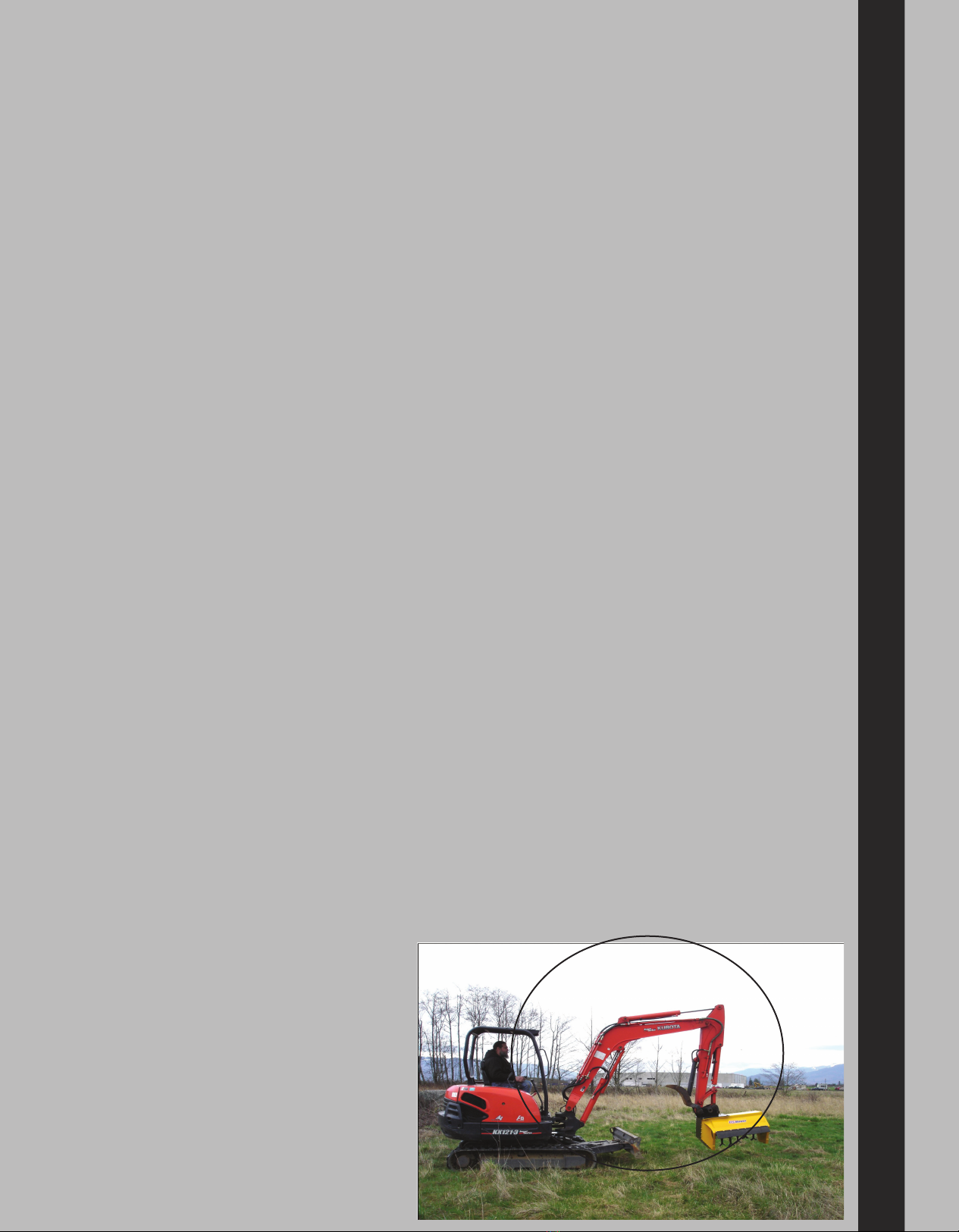
KNOW YOUR OPERATING SAFETY ZONE!!
Before starting the operator should read and understand the owner/operation manual for the
parent implement to determine the proper procedure for turning on the auxiliary hydraulics to
run the mower.
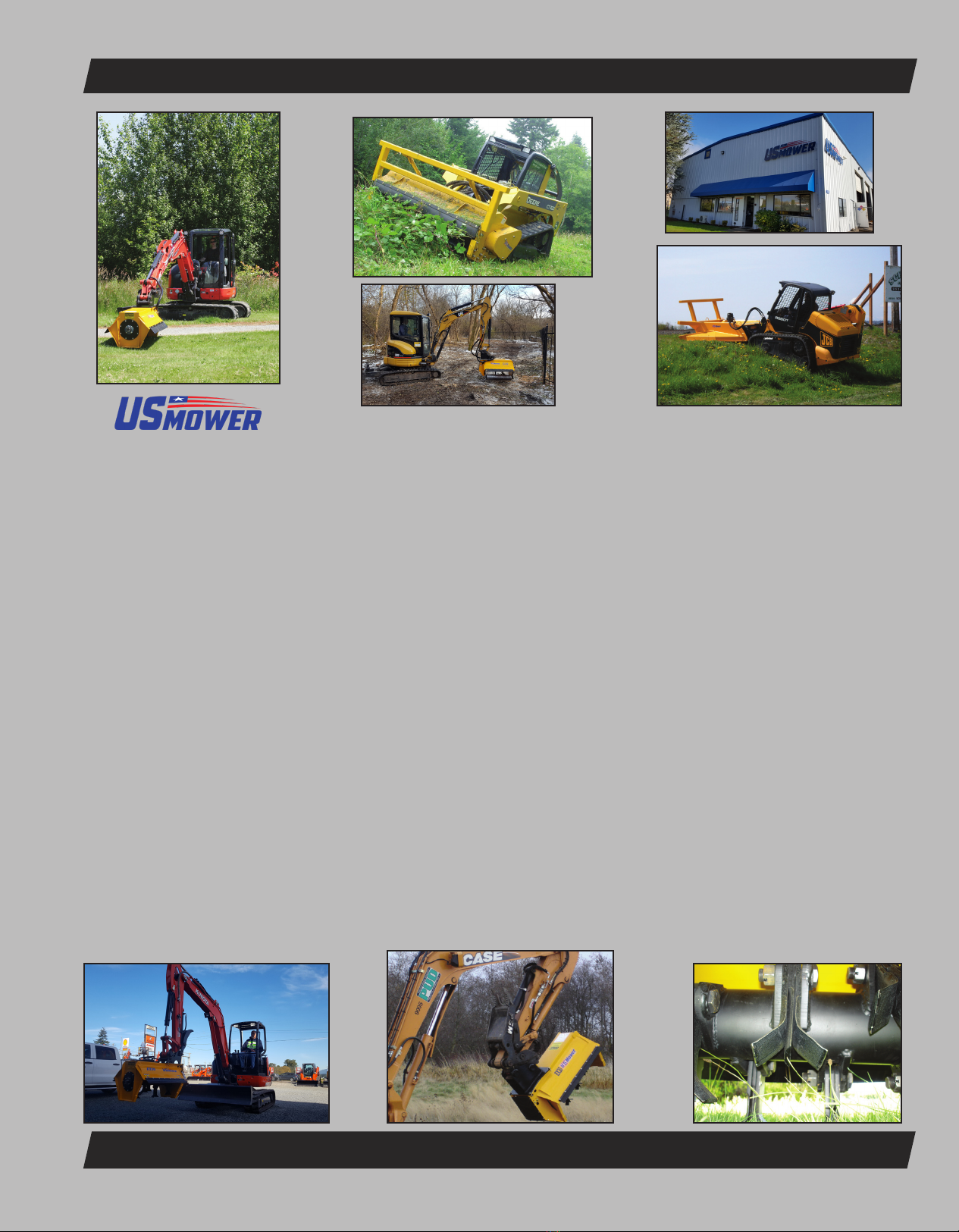
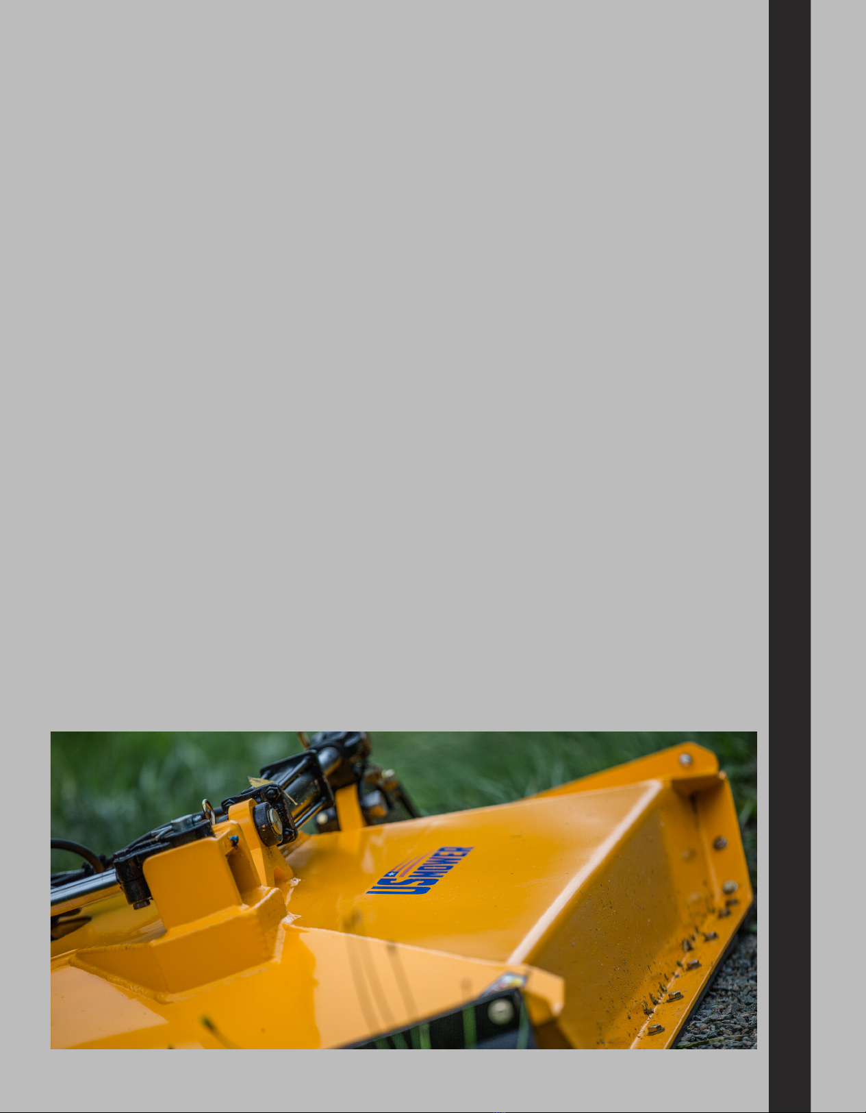
Mounting the mower
After removing the bucket from the stick by disconnecting the quick attach mechanism install the mower in it’s place. The mower with its’
mount should readily attach in place of the bucket. Conrm that the locking mechanism is properly engaged. Install the case drain line
and then, attach the supplied hoses with quick couplers to the auxilary circuit lines on the excavator. Make sure that the quick connect
couplers are completely engaged and locked.
Case drain line, what and why is it needed?
The case drain protects the motor shaft seal from excessive pressure. Motor shaft seals are usually rated to 100 psi for brief periods
or less than about 50 PSI continuously. High pressure oil from the gear section travels between the shaft and its sleeve bearing to an
area behind the shaft seal. Through the return line by way of an internal check valve or through an external case drain. In most compact
equipment return line pressure is high enough to cause either abrupt seal blowout (150+ psi) or early failure of the motor shaft. Higher
pressure seals are available, but are not always reliable and cause other problems as well.
The best solution is a dedicated case drain. Your machine may have an internal or external case drain system that can accommodate the
small volume of gear motor case ow. Contact your vehicle dealer or manufacturer for technical details.
Motor shaft seals are not covered under warranty if case drain is not properly installed or fails. Make sure
case drain line couplers are properly connected.
There are obvious and hidden potential hazards involved in the operation of this mower. Serious injury
or death may occur unless care is taken to insure the safety of both the operator and other persons
in the area. The following is a list of some safeguards which should be followed.