4 Operation
8Operating instructions recoVAIR 0020159950_07
4.4 Operator level –overview
The appendix contains the complete overview of the end
user level. The most important menu points are explained
below.
Operator level –overview (→Page 13)
4.4.1 Reading the energy yield
Menu →Energy yield →
You can use this function to read the energy yield for the
entire operation.
If a controller is connected, you can also read the energy
yield for the previous day, month and year.
The output figure represents the relationship between re-
covered and used energy.
4.4.2 Reading the Live Monitor (current status)
Menu →Live Monitor →
You can use the Live Monitor function to read the current
status of the product, the connected components, and the
temperature and parameter values. The display is automatic-
ally updated.
4.4.3 Reading contact details
Menu →Information →Contact data
If your competent person has entered their telephone num-
ber during the installation, you can read the telephone num-
ber under Contact details.
4.4.4 Reading serial and article numbers
Menu →Information →Serial number
You can use this function to read the serial and article num-
ber. The article number is found in the second line of the
serial number.
4.4.5 Reading the filter change
Menu →Information →Days until filter chg.
You can use this function to read when the filters have to be
replaced.
4.4.6 Filter change overdue
Menu →Information →Filter chg. overdue
You can use this function to read by how long the filter
change is overdue.
4.4.7 Reading the maintenance interval
Menu →Information →Days until maint.
You can use this function to read when you should have your
product serviced.
4.4.8 Maintenance interval overdue
Menu →Information →Maintenance overdue
You can use this function to read by how long the mainten-
ance for your product is overdue.
4.4.9 Setting the language
Menu →Basic settings →Language
You can use this function to change the language settings
for your product.
4.4.10 Set display contrast
Menu →Basic settings →Display contrast
You can use this function to set the display contrast.
4.4.11 Setting the heat recovery
Menu →Basic settings →Heat recovery
You can use this function to set the heat recovery.
–Auto heat recovery (recommended): The bypass is auto-
matically closed/opened depending on the outside tem-
perature.
–Heat recovery on: The bypass is closed.
–Heat recovery off: The bypass is open.
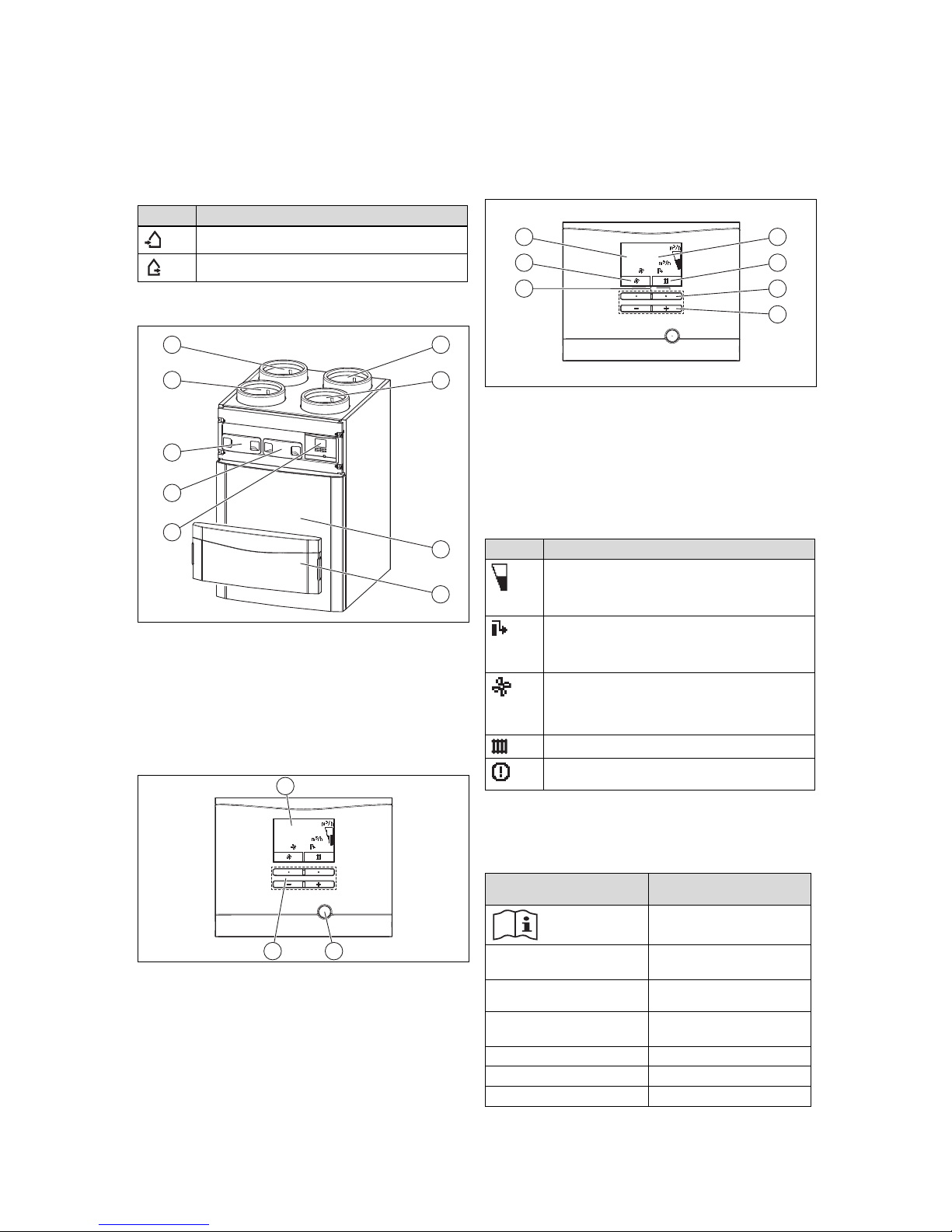
4.5 Switching the product on/off
The mains plug/circuit breaker (depending on the country)
must remain accessible after the installation by the compet-
ent person and during the entire time the product is operat-
ing.
4.5.1 Switching on the product
▶Plug the product's mains plug into the earthed plug
socket (230 V) or use the circuit breaker (depending on
the country) to switch on the product.
◁The product's electronics start up.
◁The basic display appears on the display.
4.5.2 Switching off the product
▶Pull the product's mains plug out of the earthed plug
socket (230 V) or use the circuit breaker (depending on
the country) to switch off the product.
4.6 Setting the ventilation
4.6.1 Setting the ventilation on the product
1. Alternatives 1 / 2
▶Press in the basic display.
▶Use and to select the de-
sired ventilation level.
–Adjustment range: Nominal ventilation,In-
creased ventil.,Reduced ventilation,Auto
Ventilation levels –Overview (→Page 14)
▶Confirm by pressing .
1. Alternatives 2 / 2
▶Press in the basic display.
▶Press .
▶Use and to select the de-
sired ventilation level.